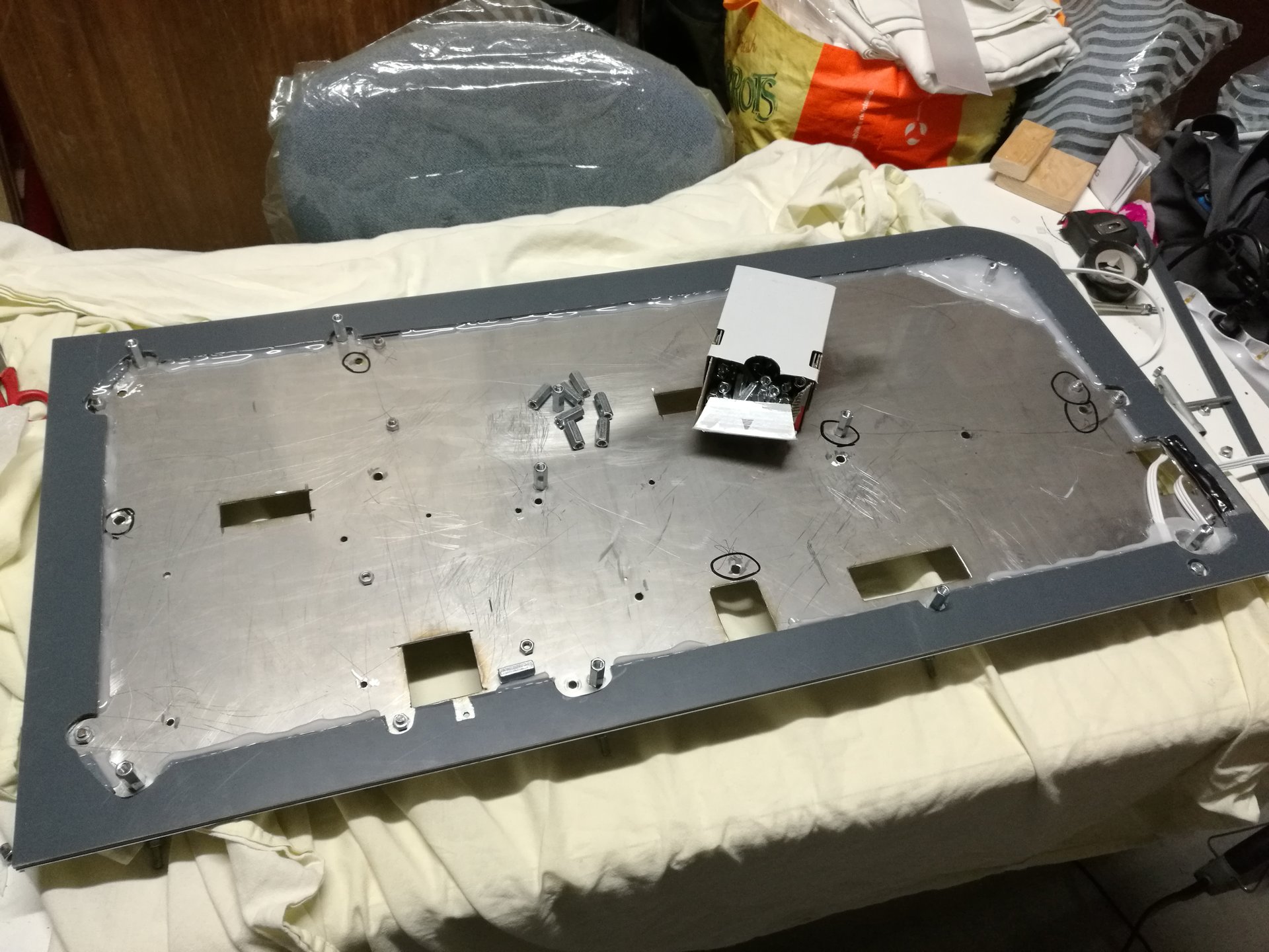
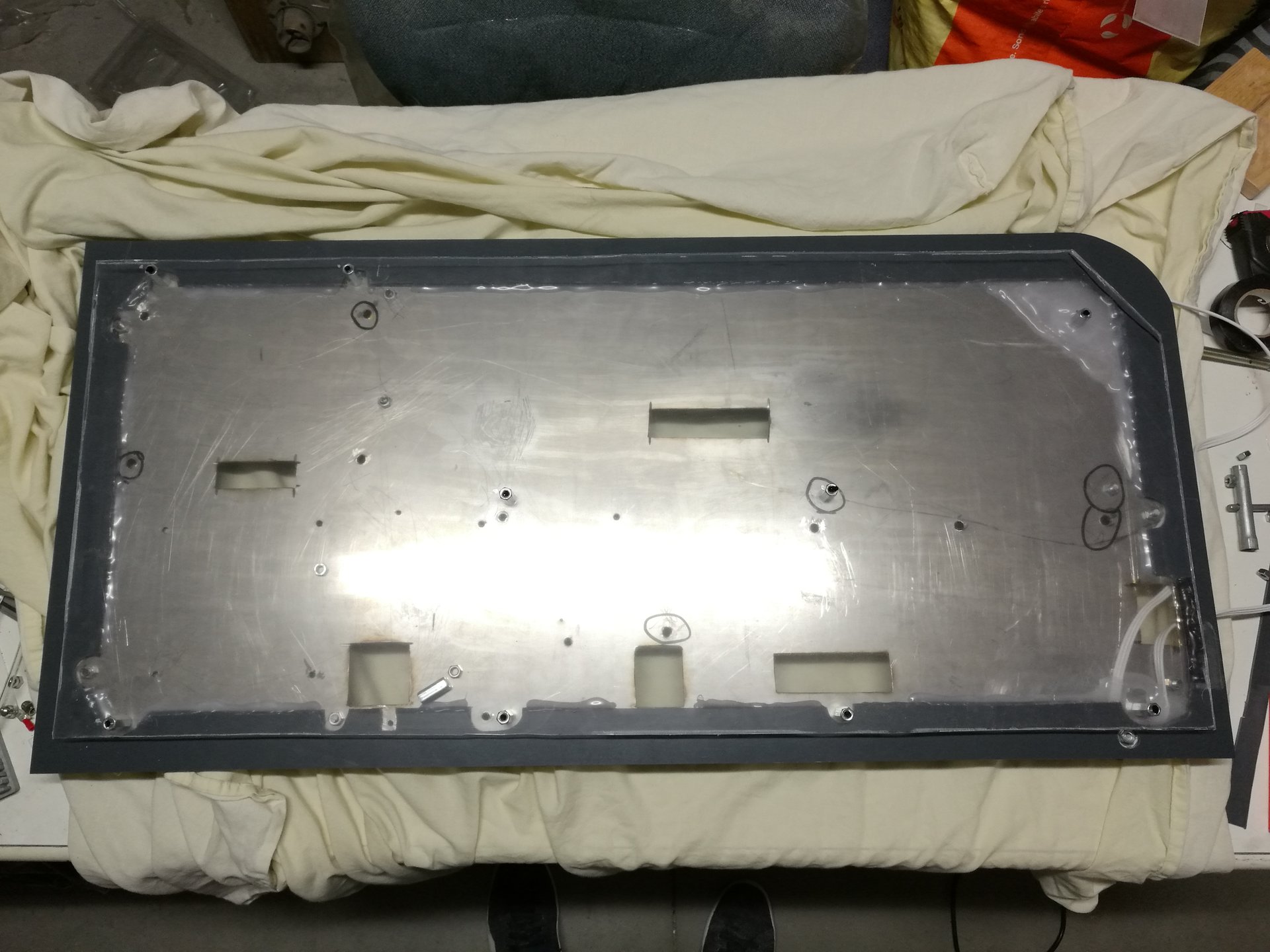
After completing the base, I have made the bottom panel that keeps in place all the cables in the interspace under the base.
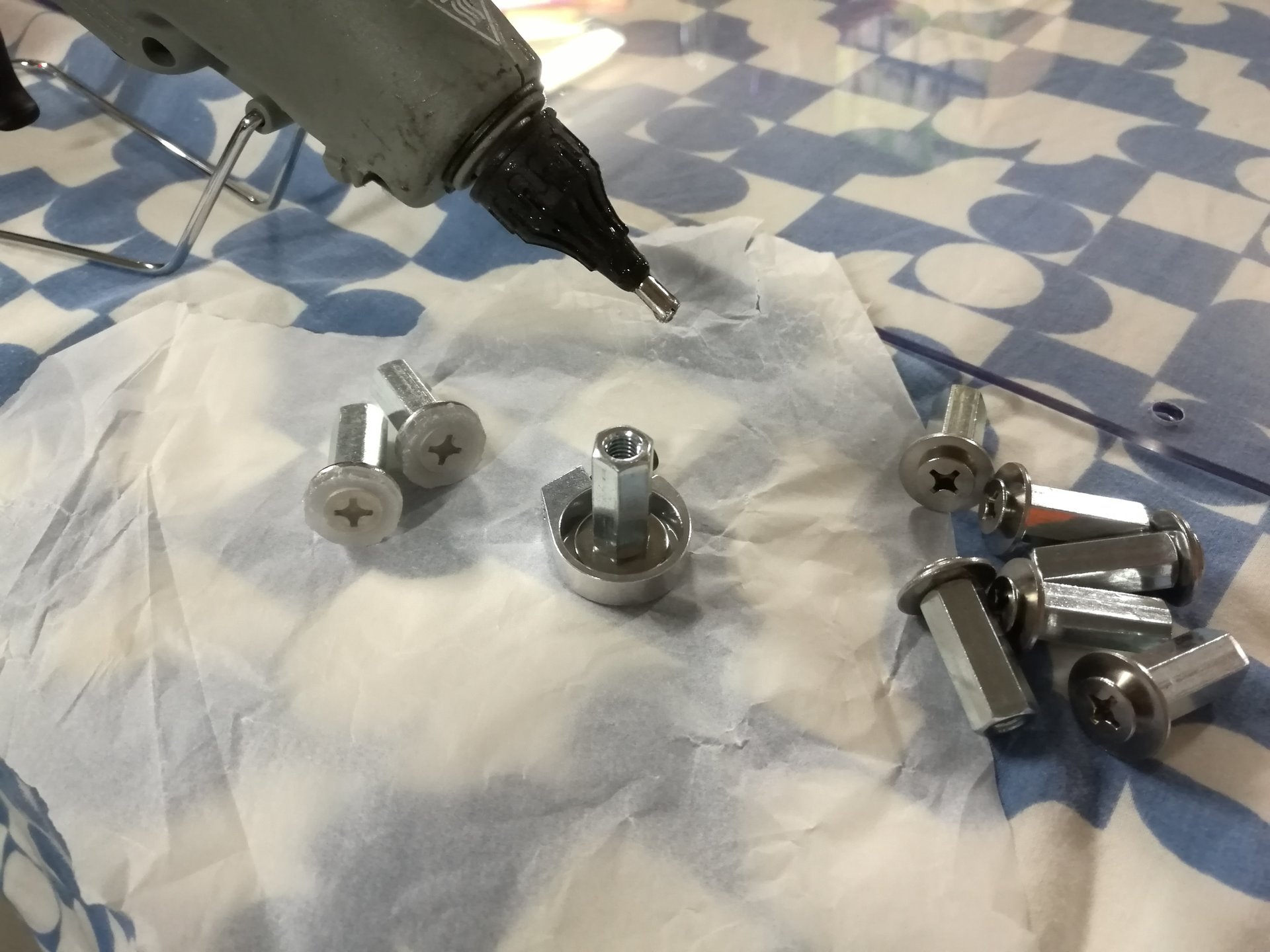
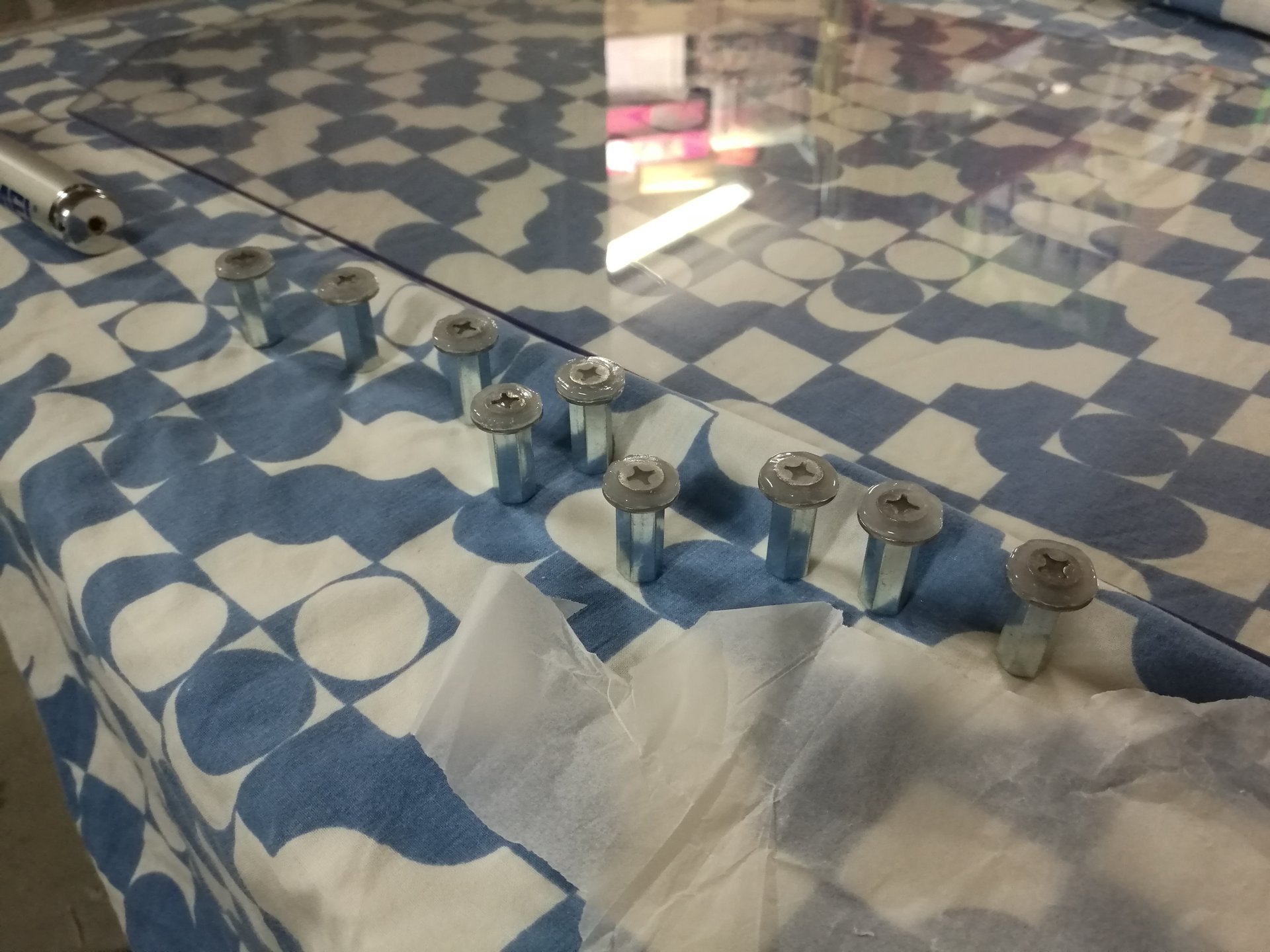
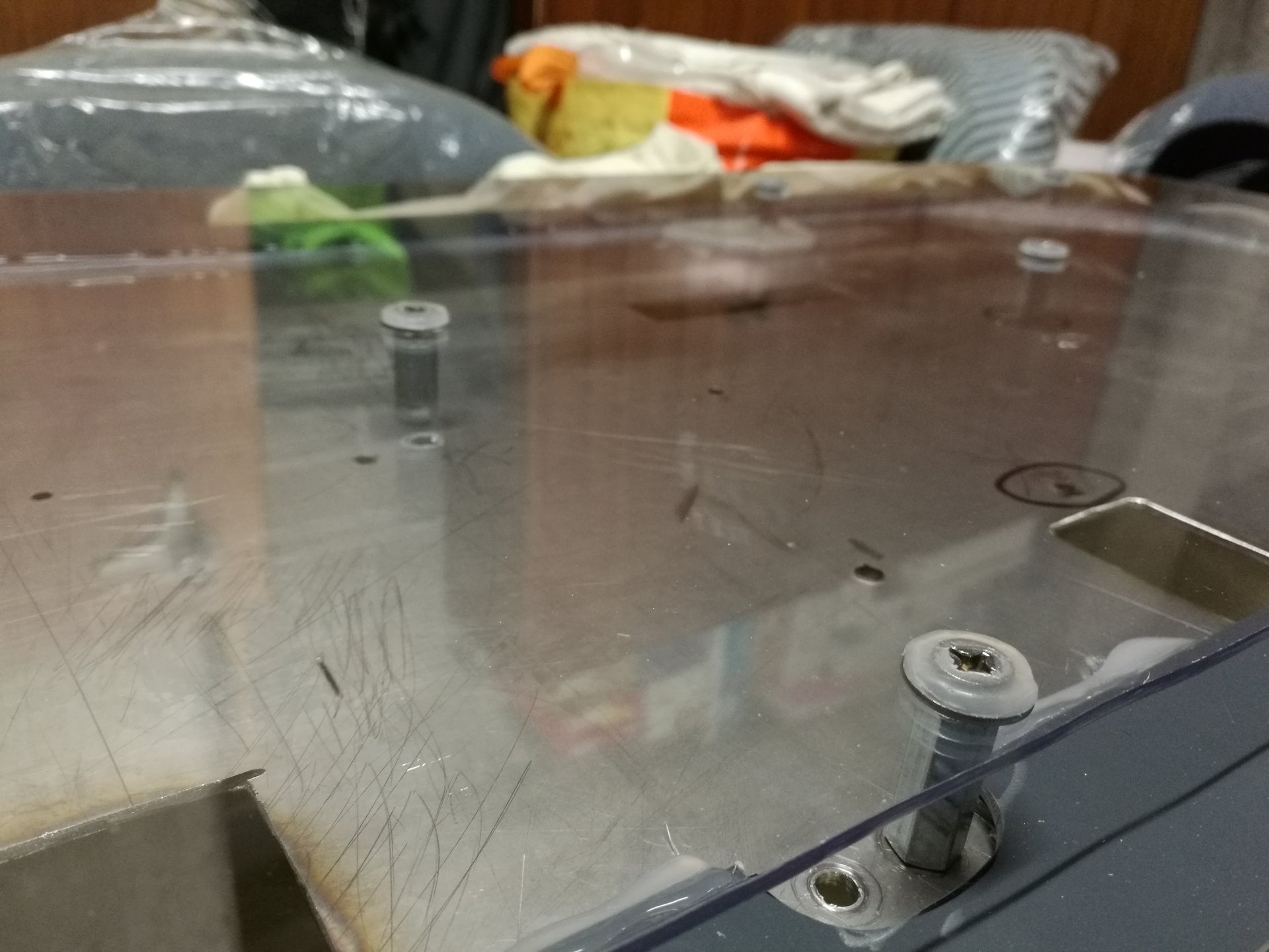
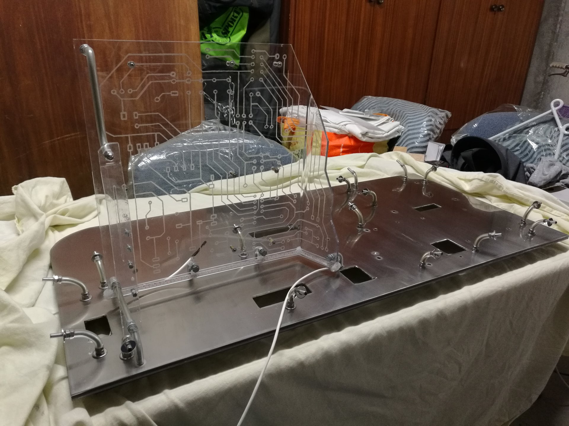
I wanted to make it as invisible as possible, so I used a trasparent polycarbonate panel, fixed under the base by some 25mm high junction nuts.
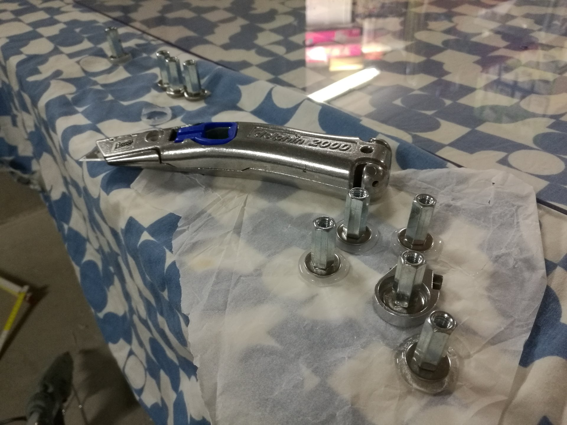
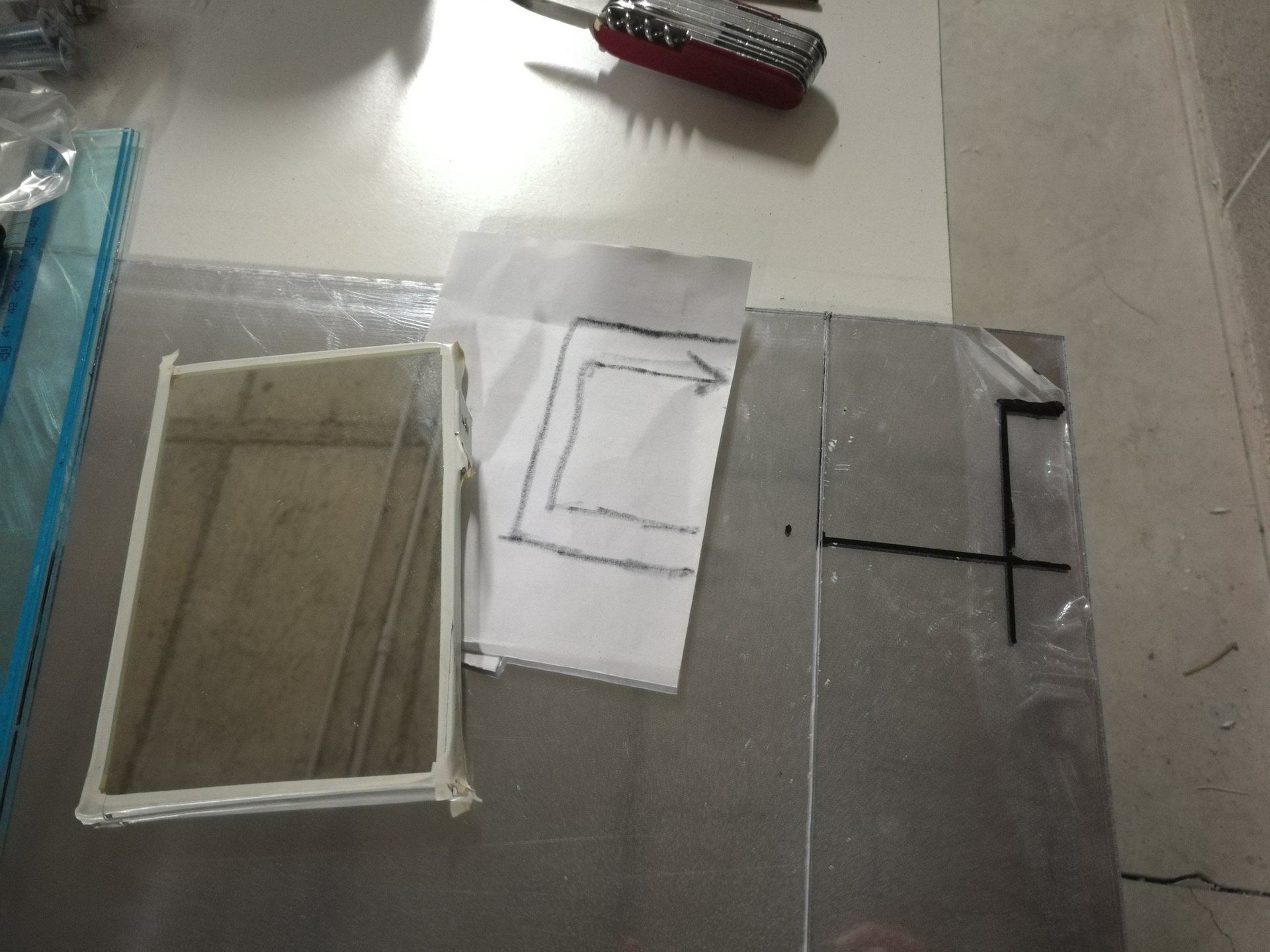
Here I’m taking the measures and cutting the panel:


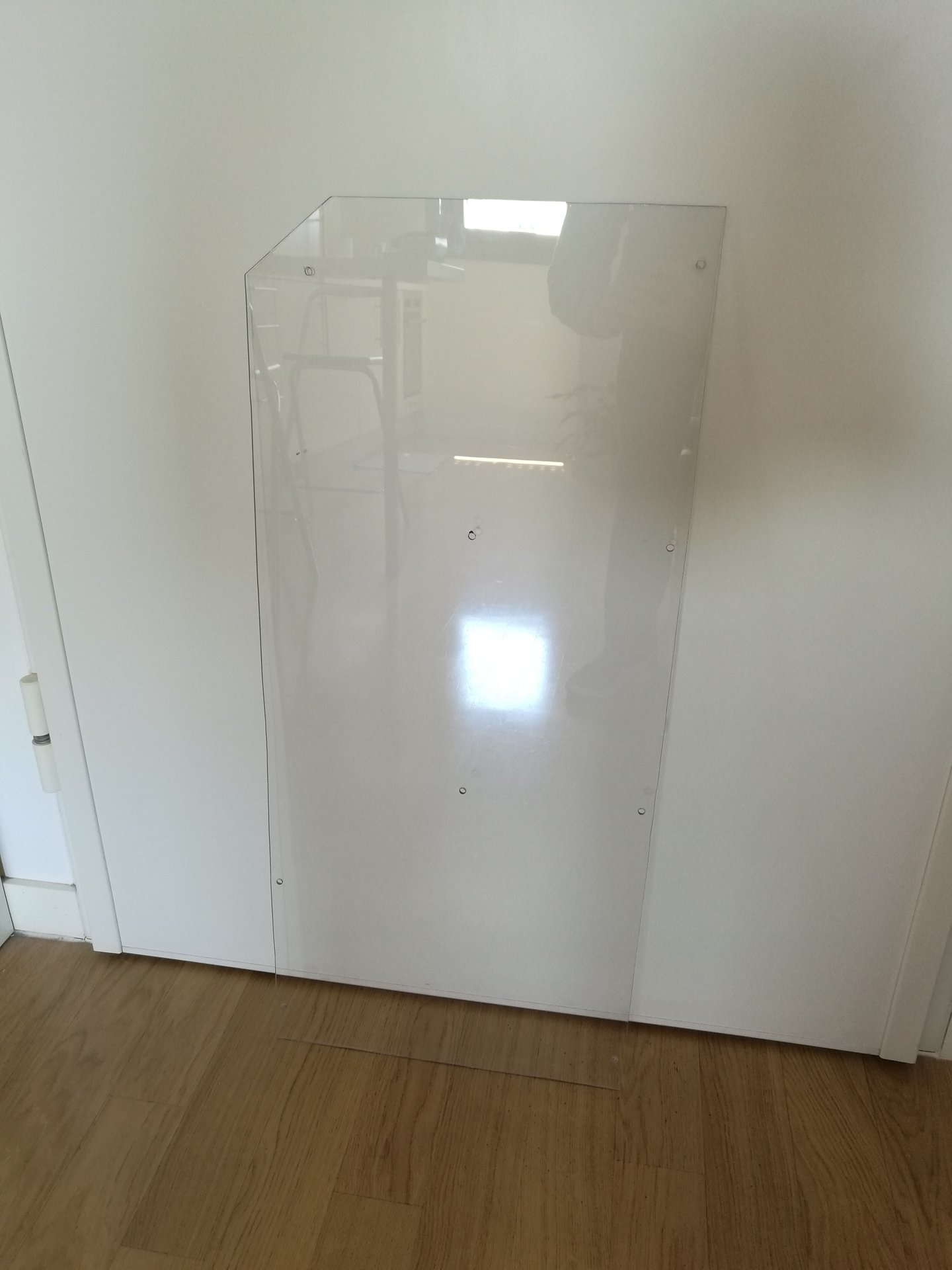
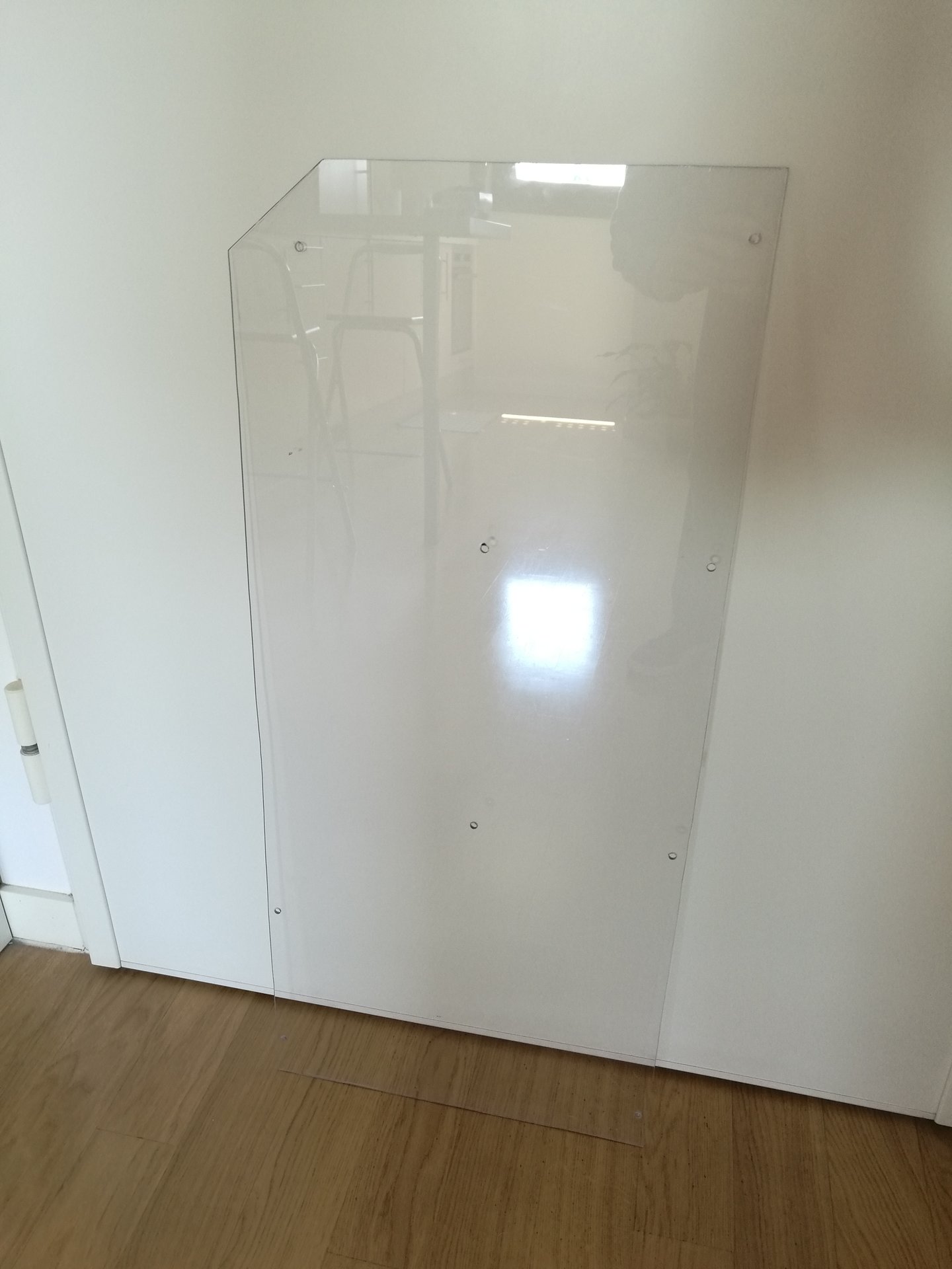
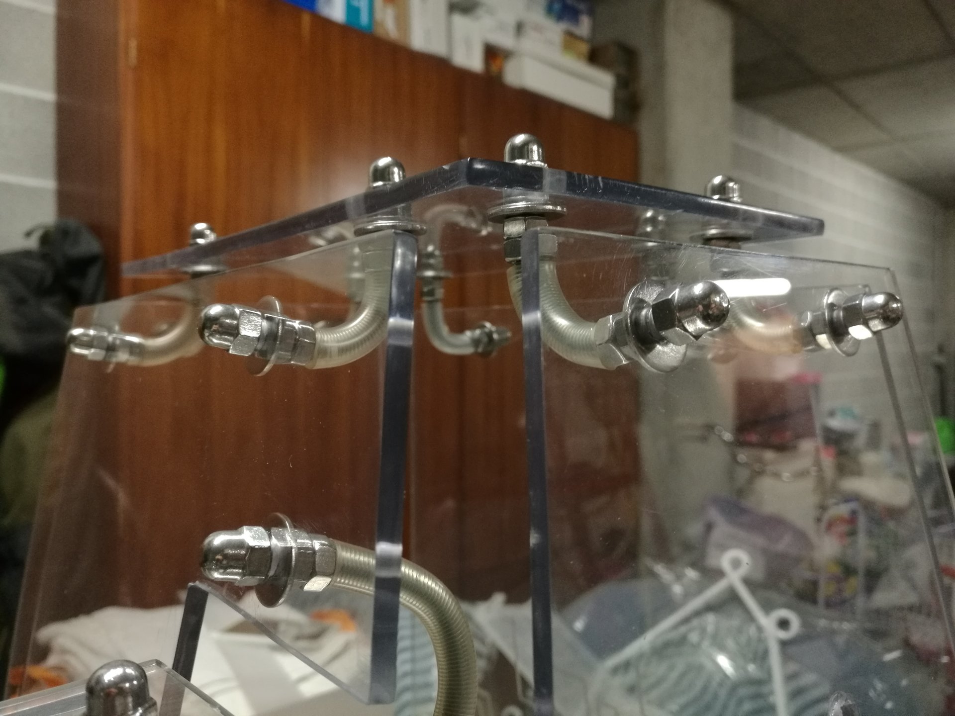
These bolts have two purposes: they fix the panel to the junction nuts, but they also serve as feet for the case (putting felt pads on the bolts’ heads):
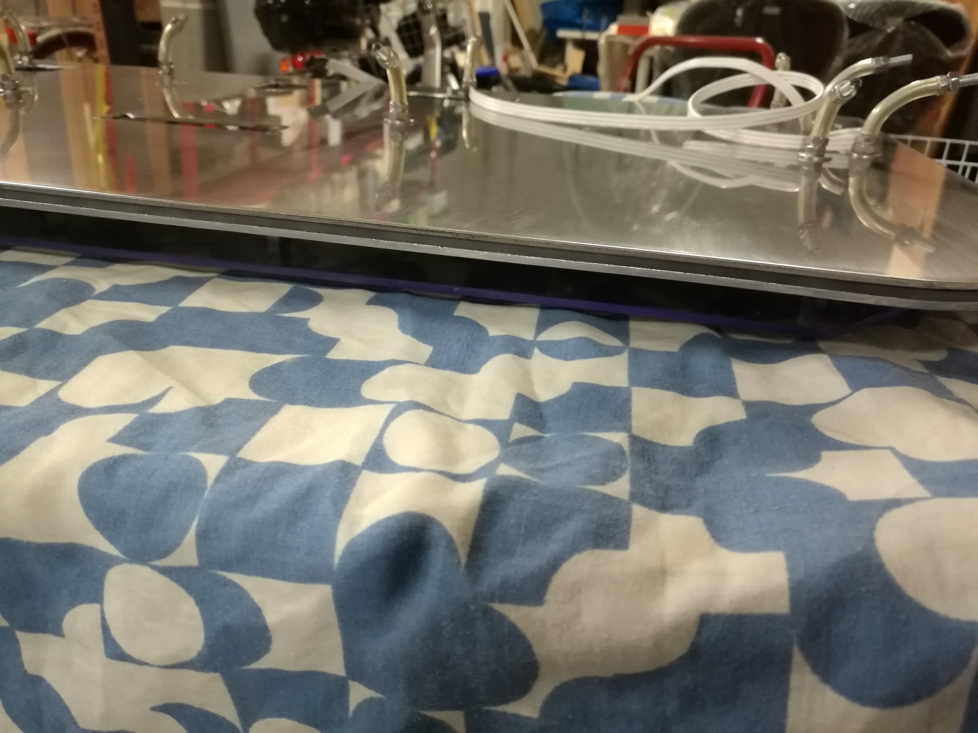
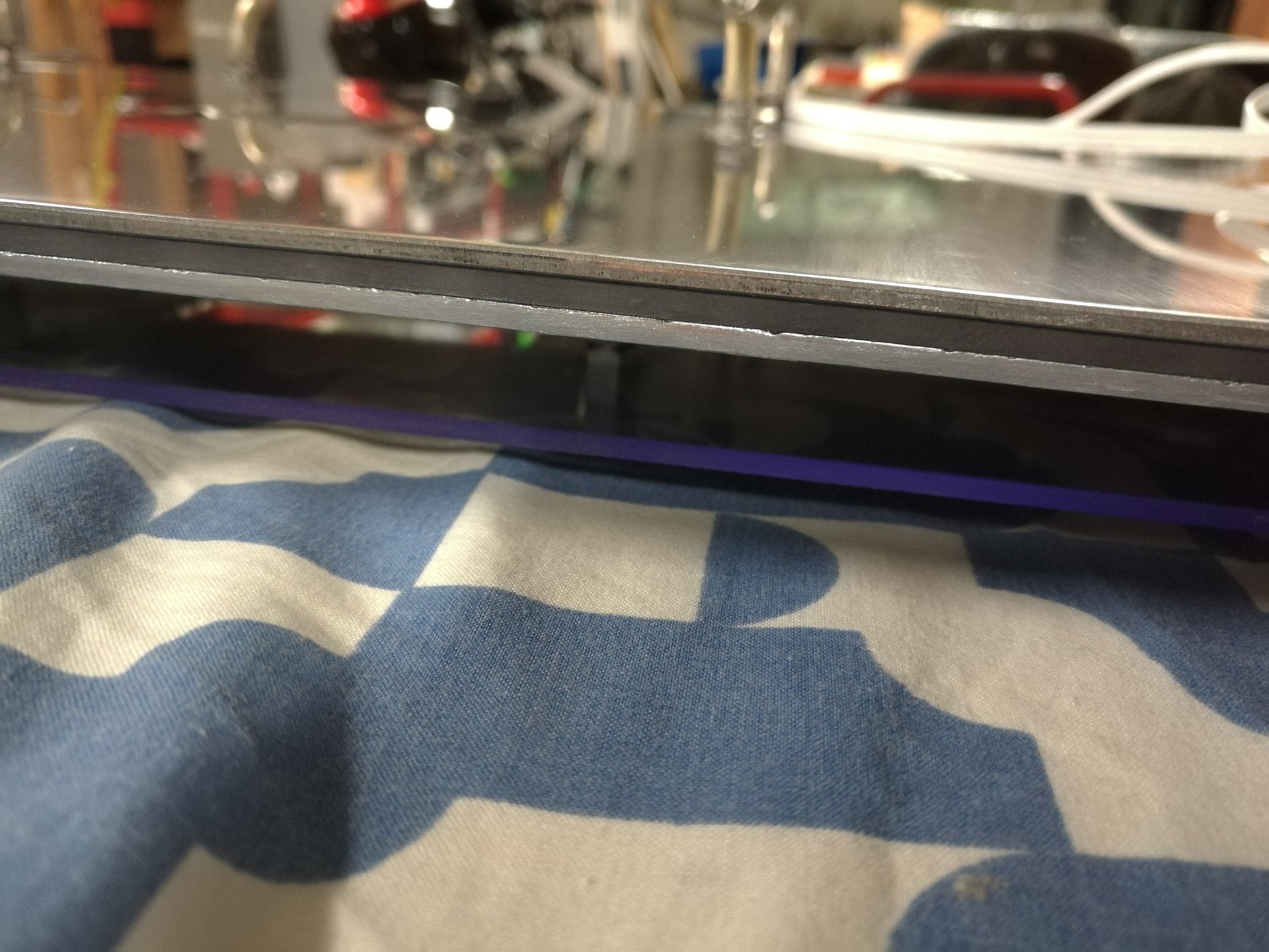
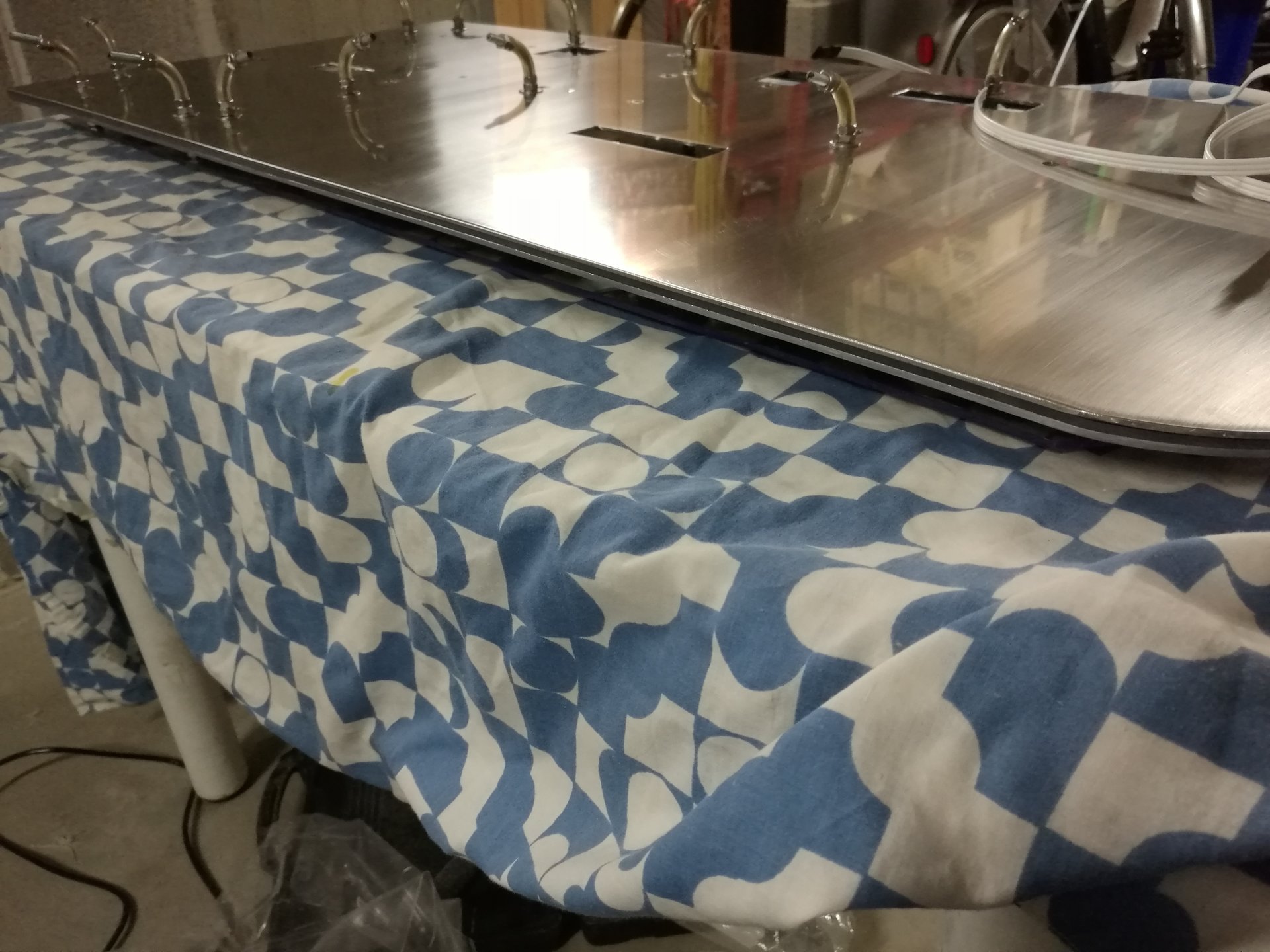
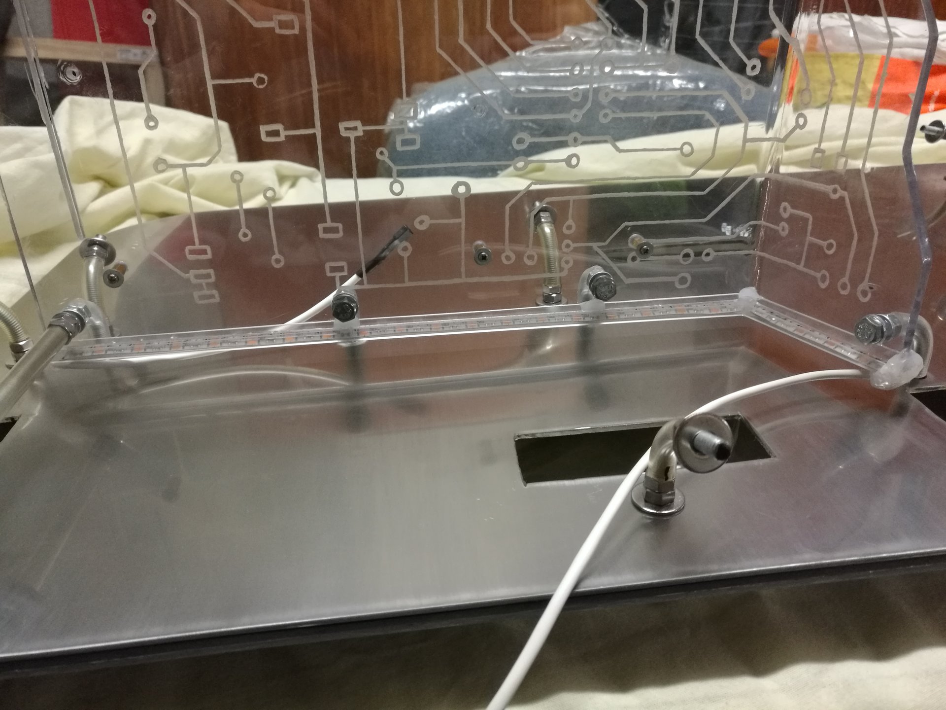
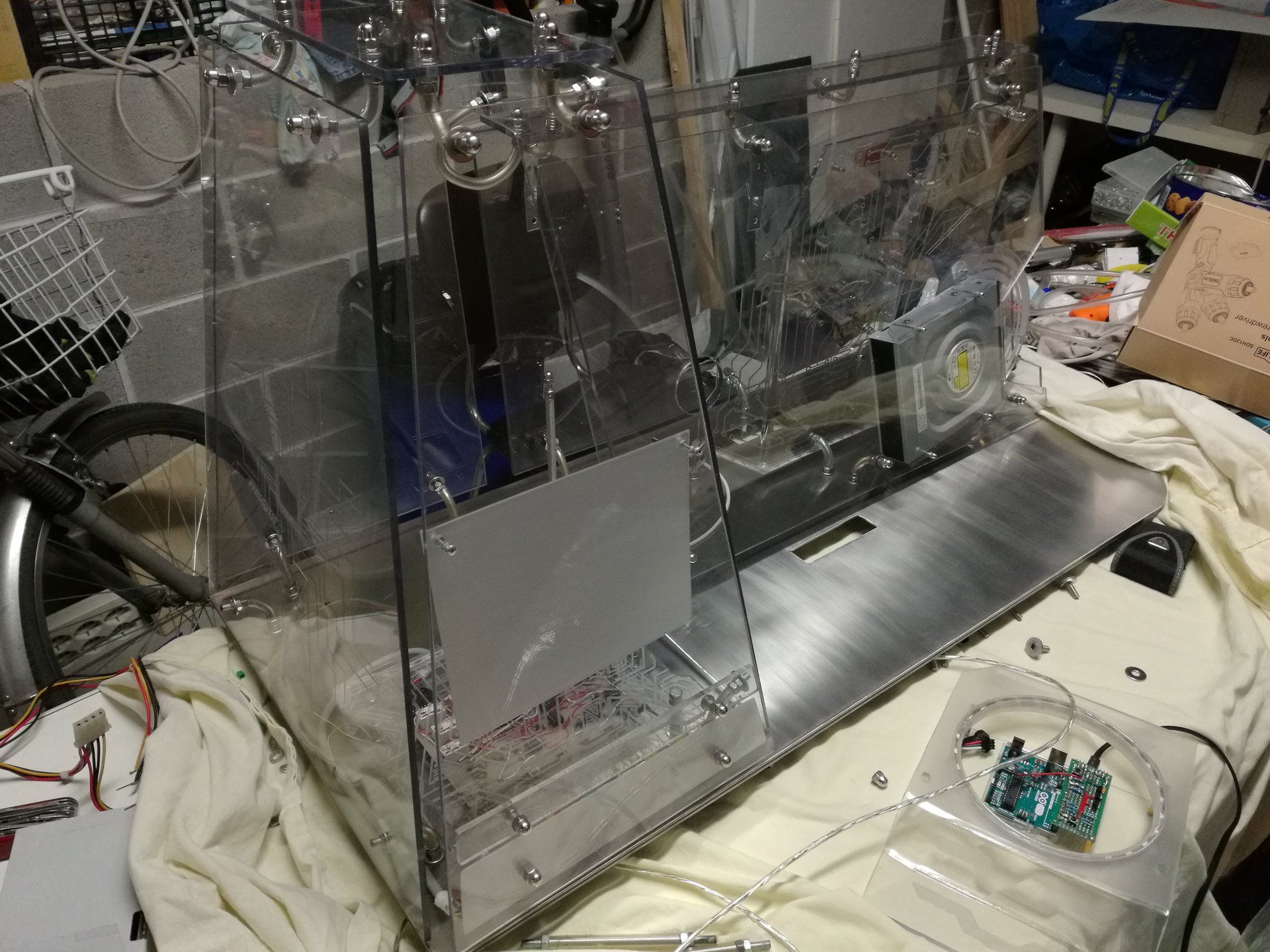
I mount the panel under the base:
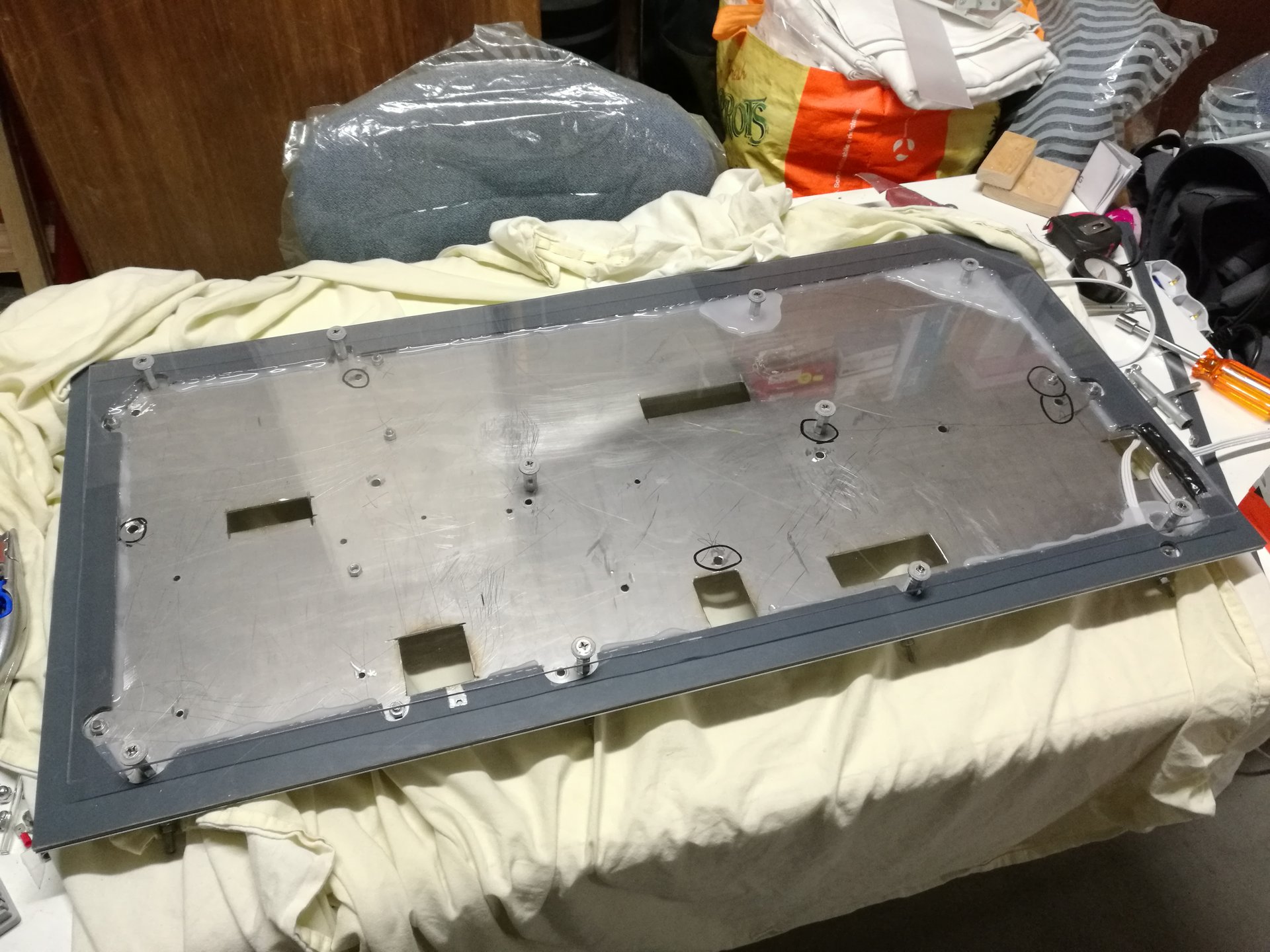
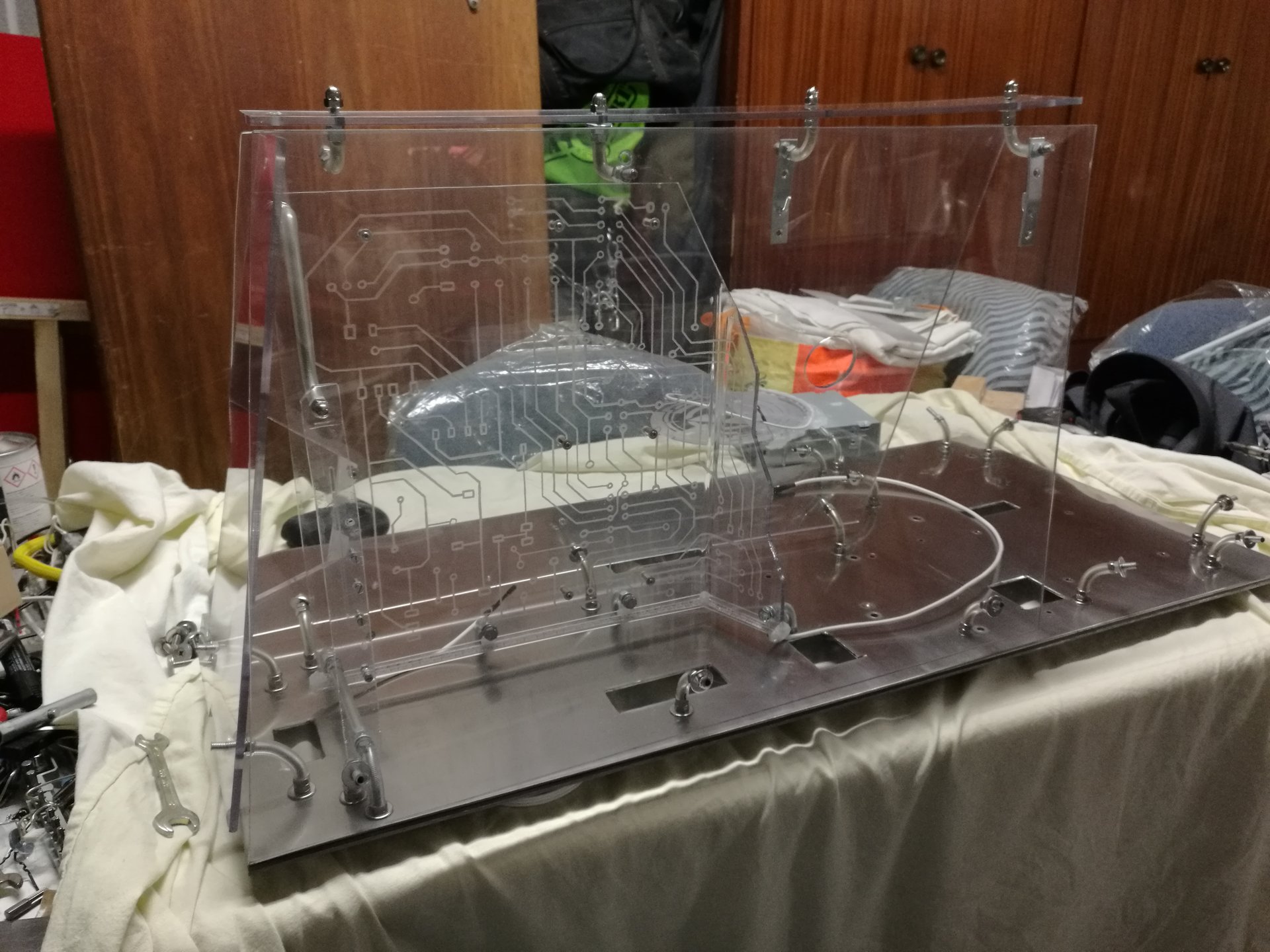
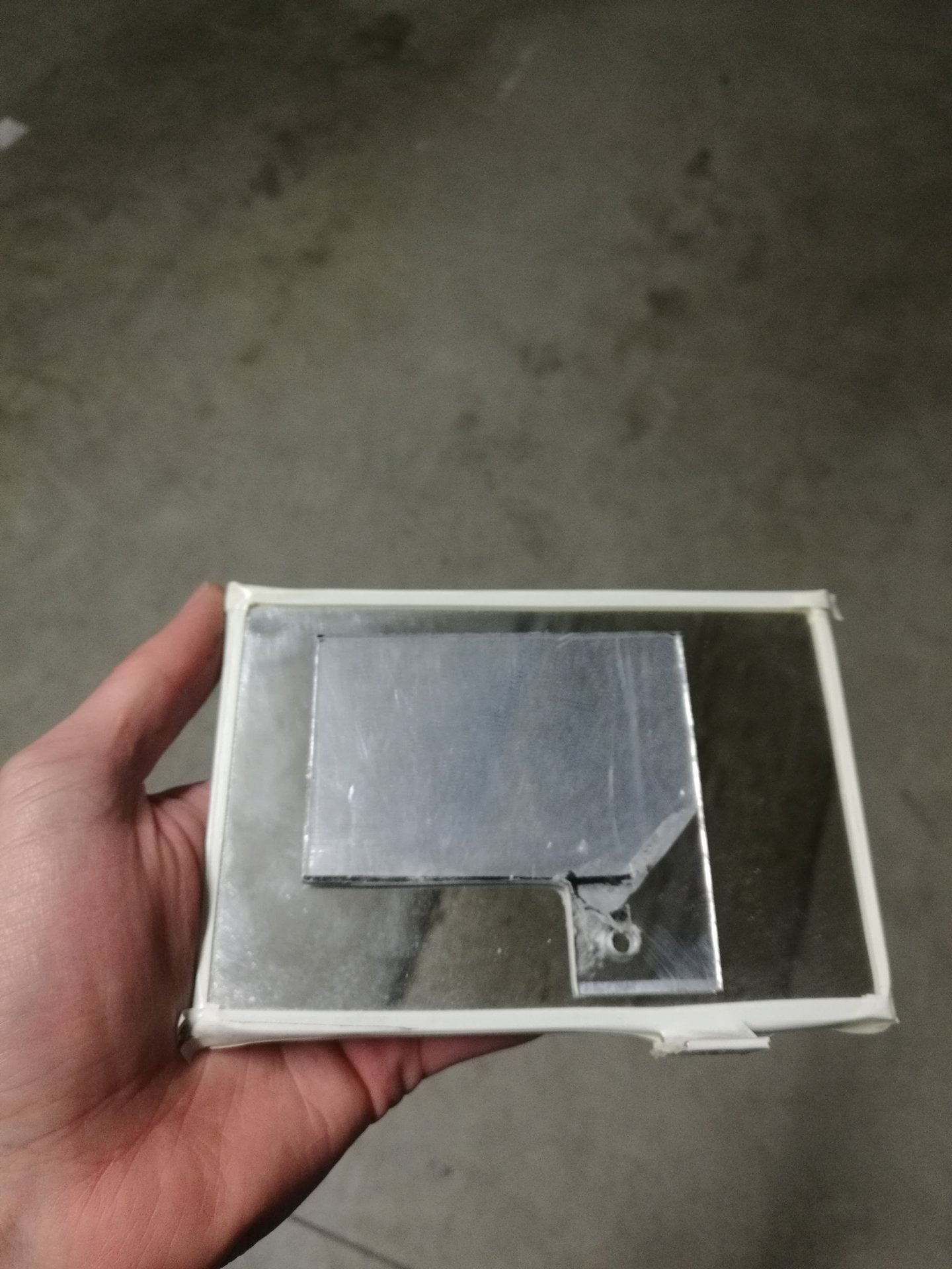
And this is how the panel appears from above, it is almost invisible:

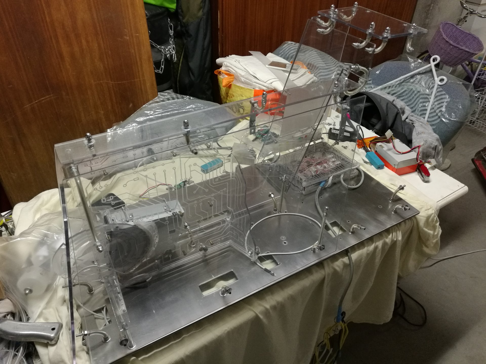
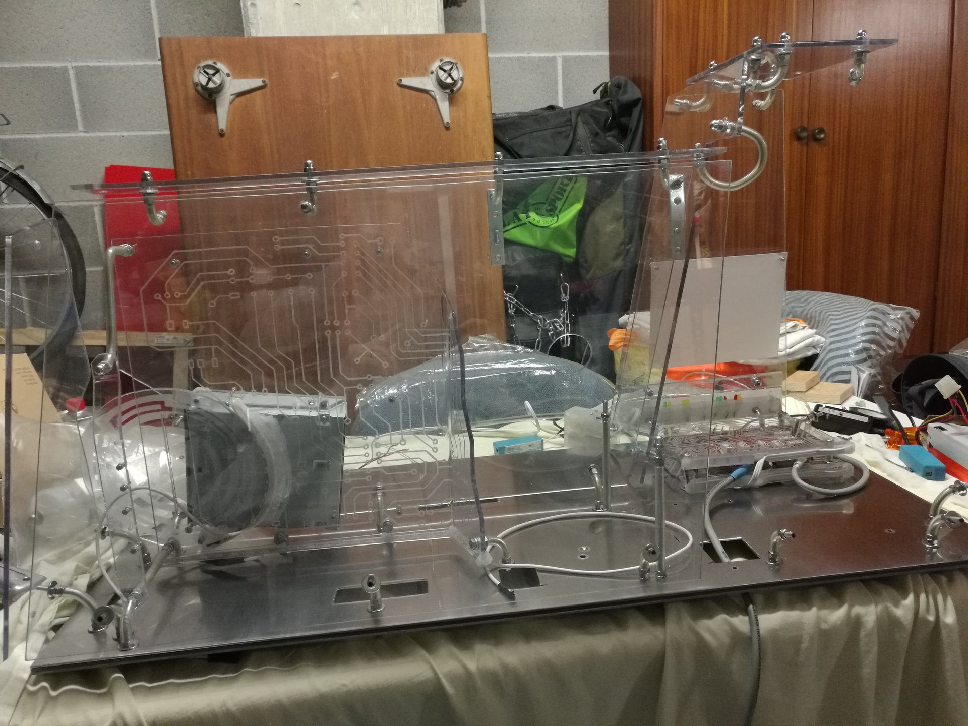
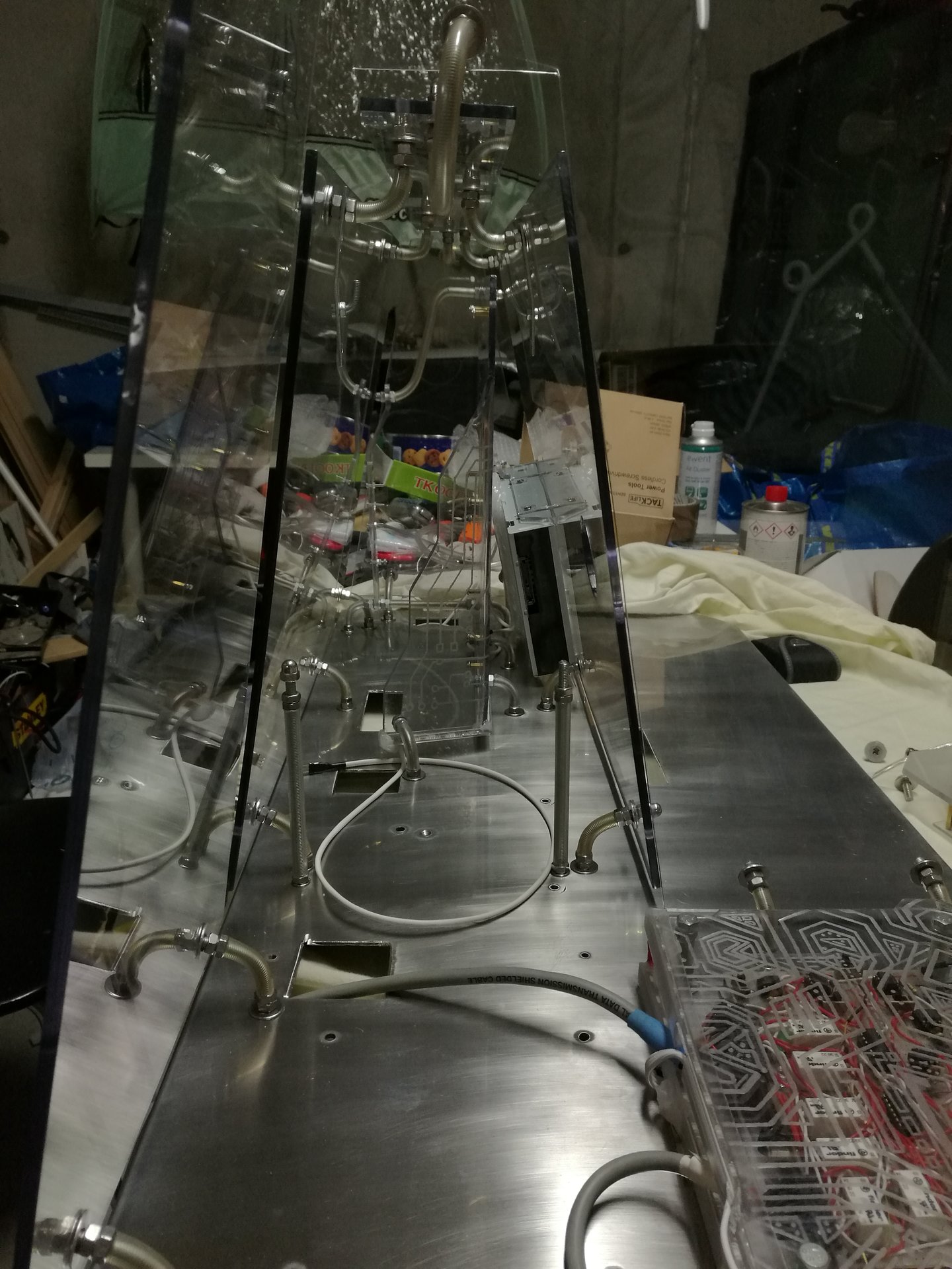
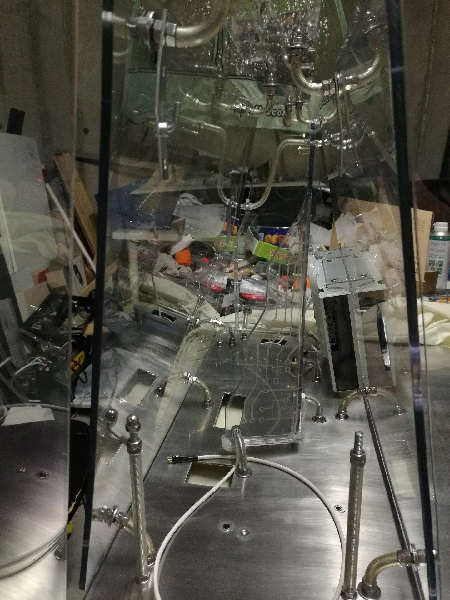
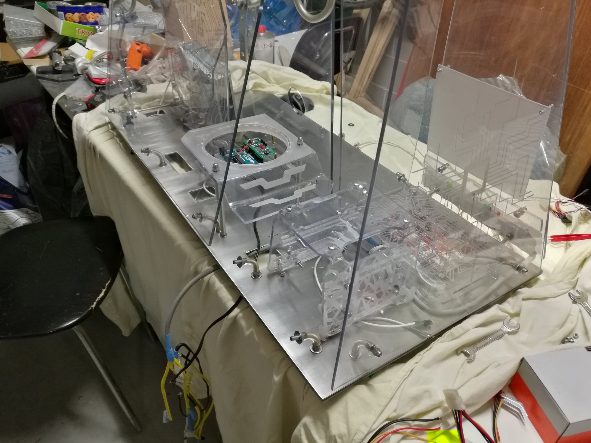
And now it has finally arrived the moment to reassemble all the parts of the case!
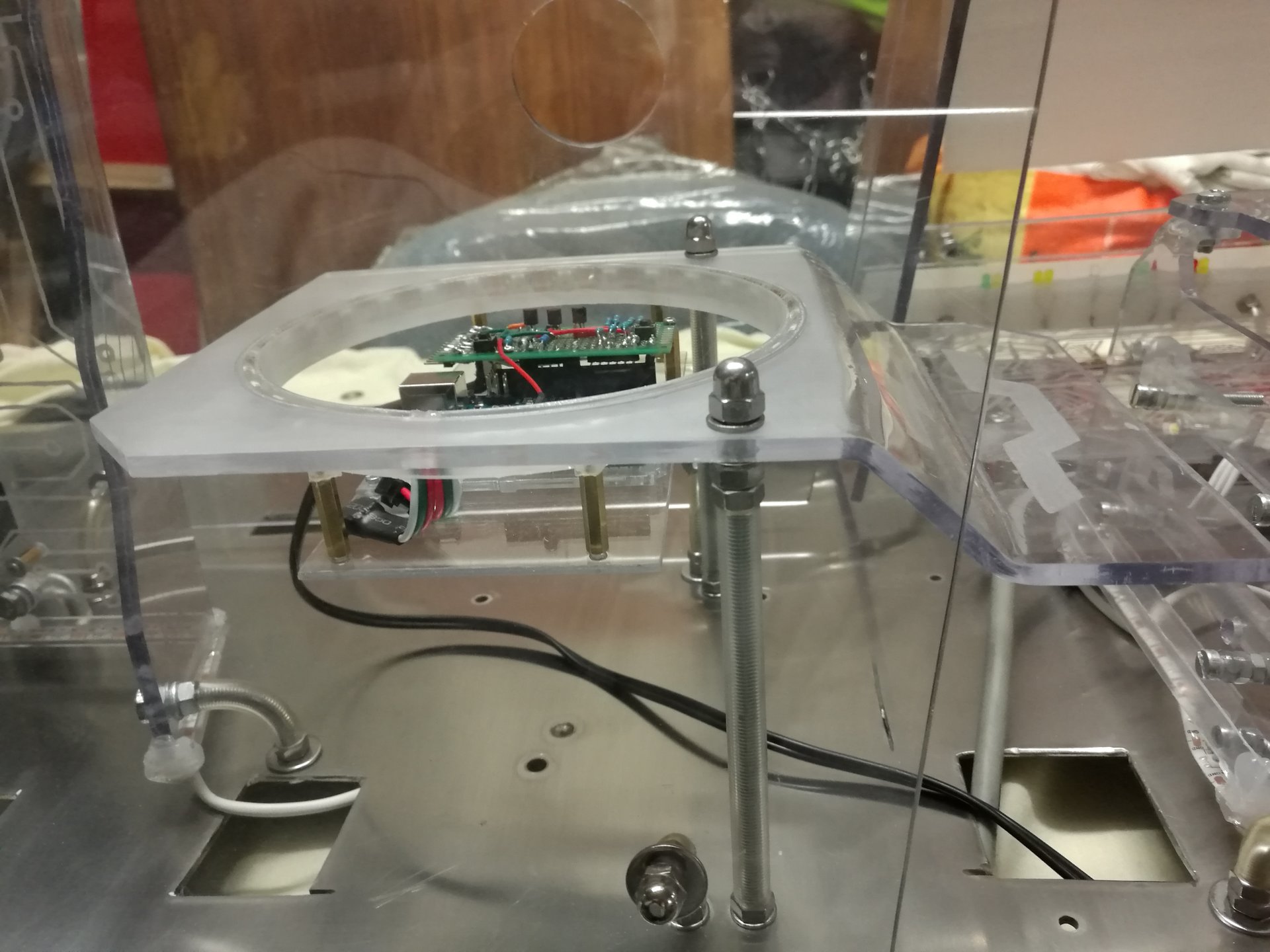
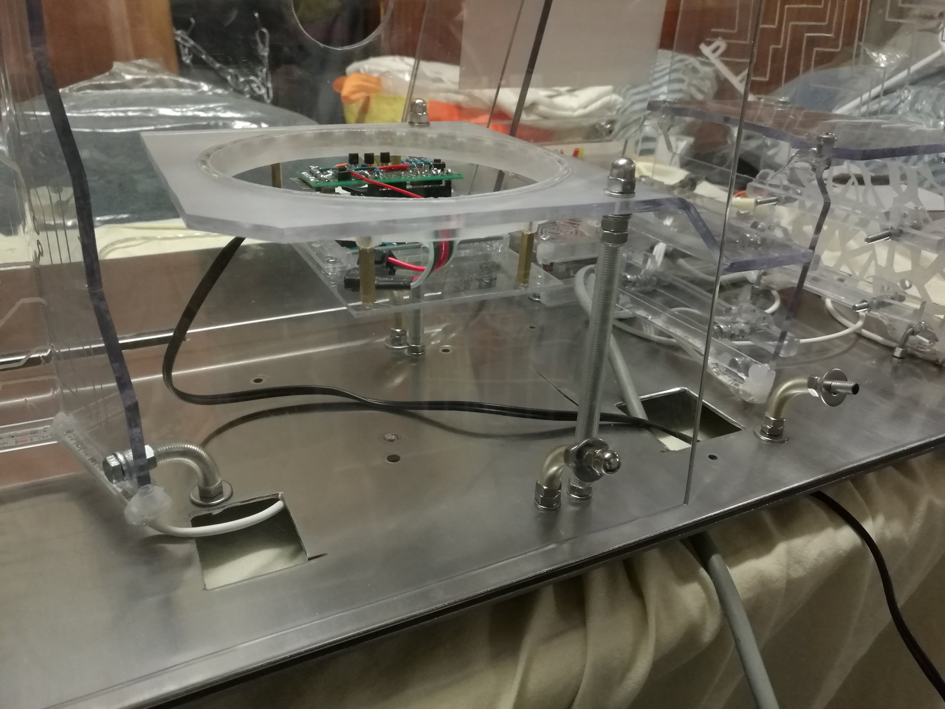
Motherboard structure:
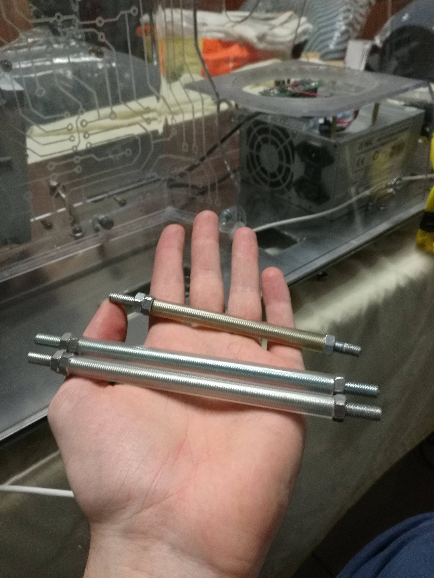
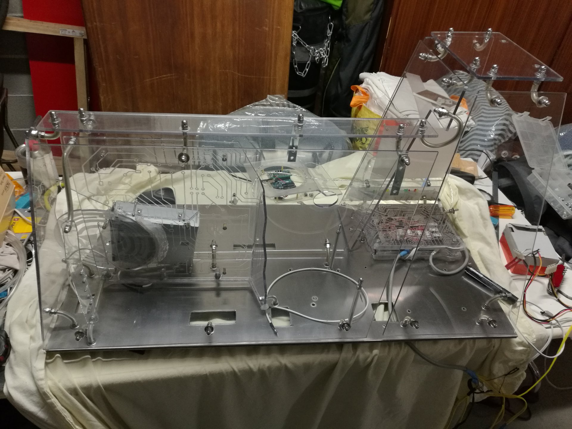
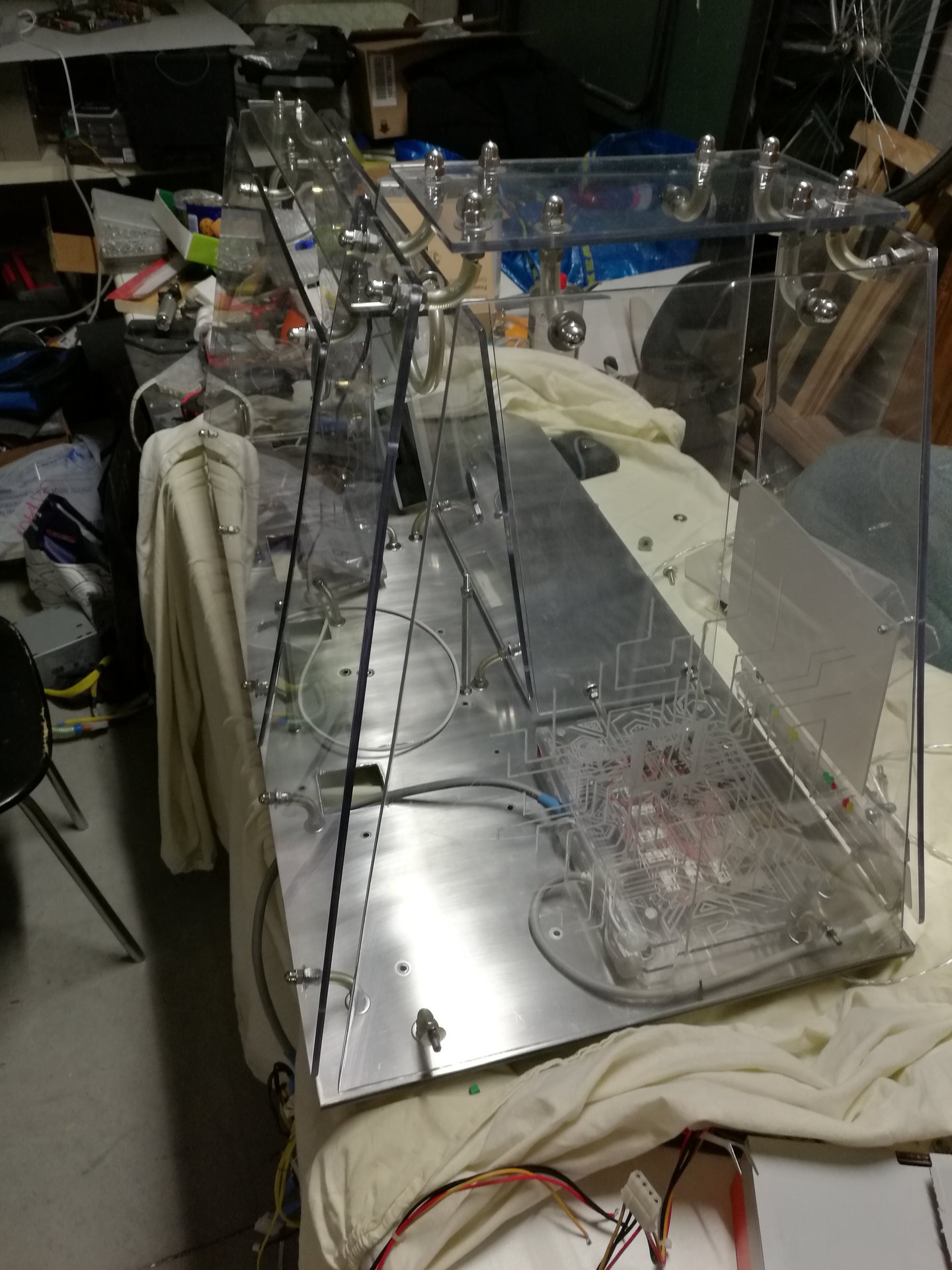
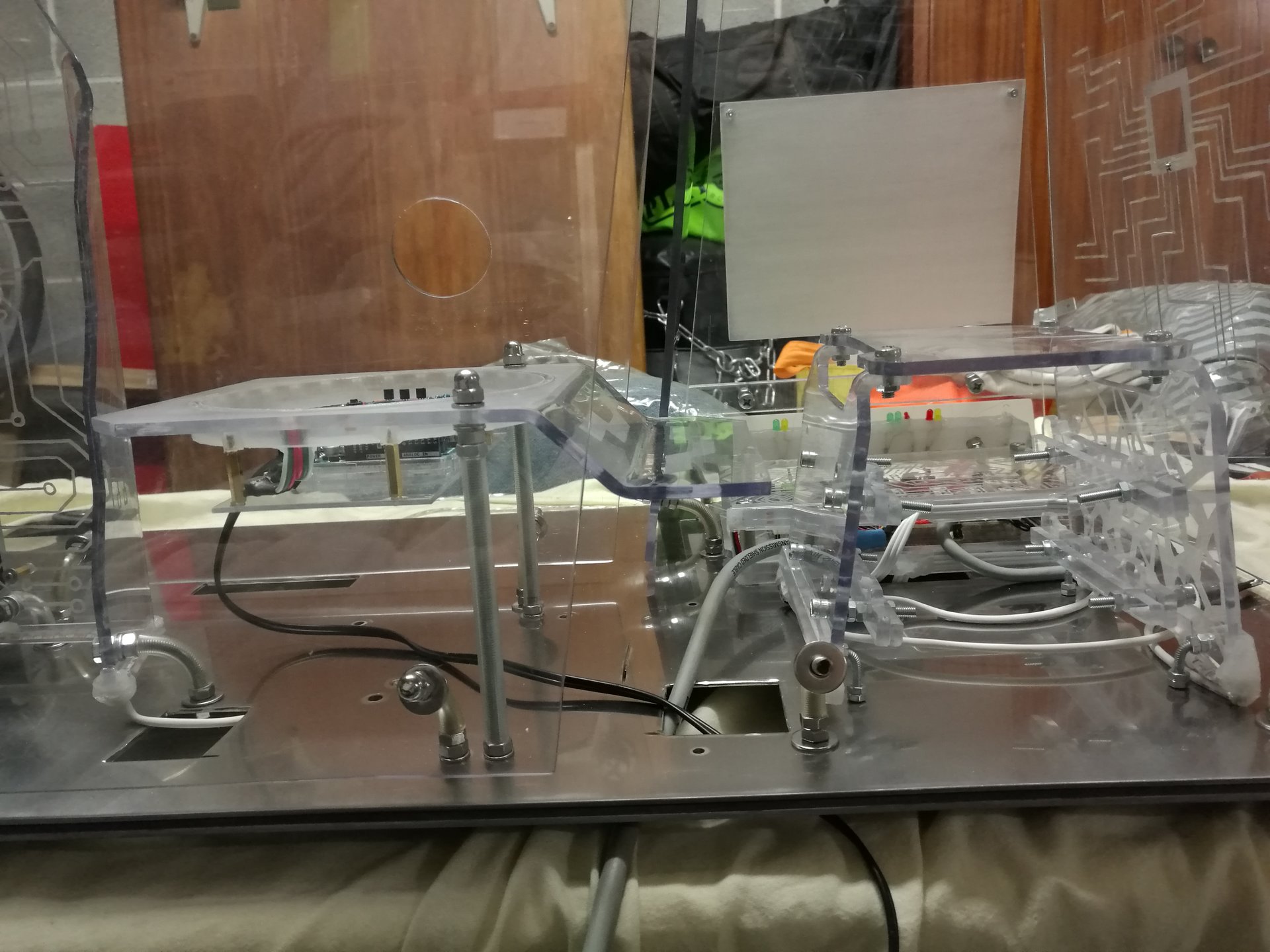
I have had to replace the two threaded bars of the PSU cover with two longer bars, because my current PSU is bigger than the old one, and also I needed some space for Arduino:
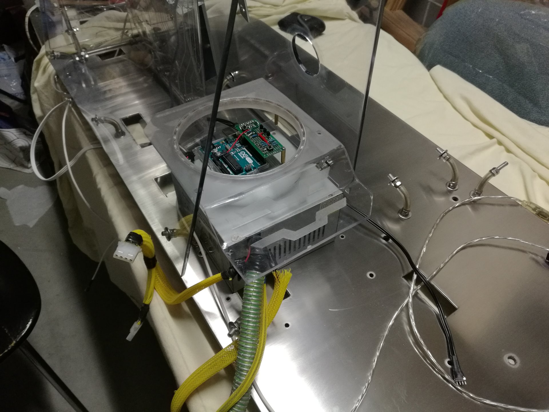
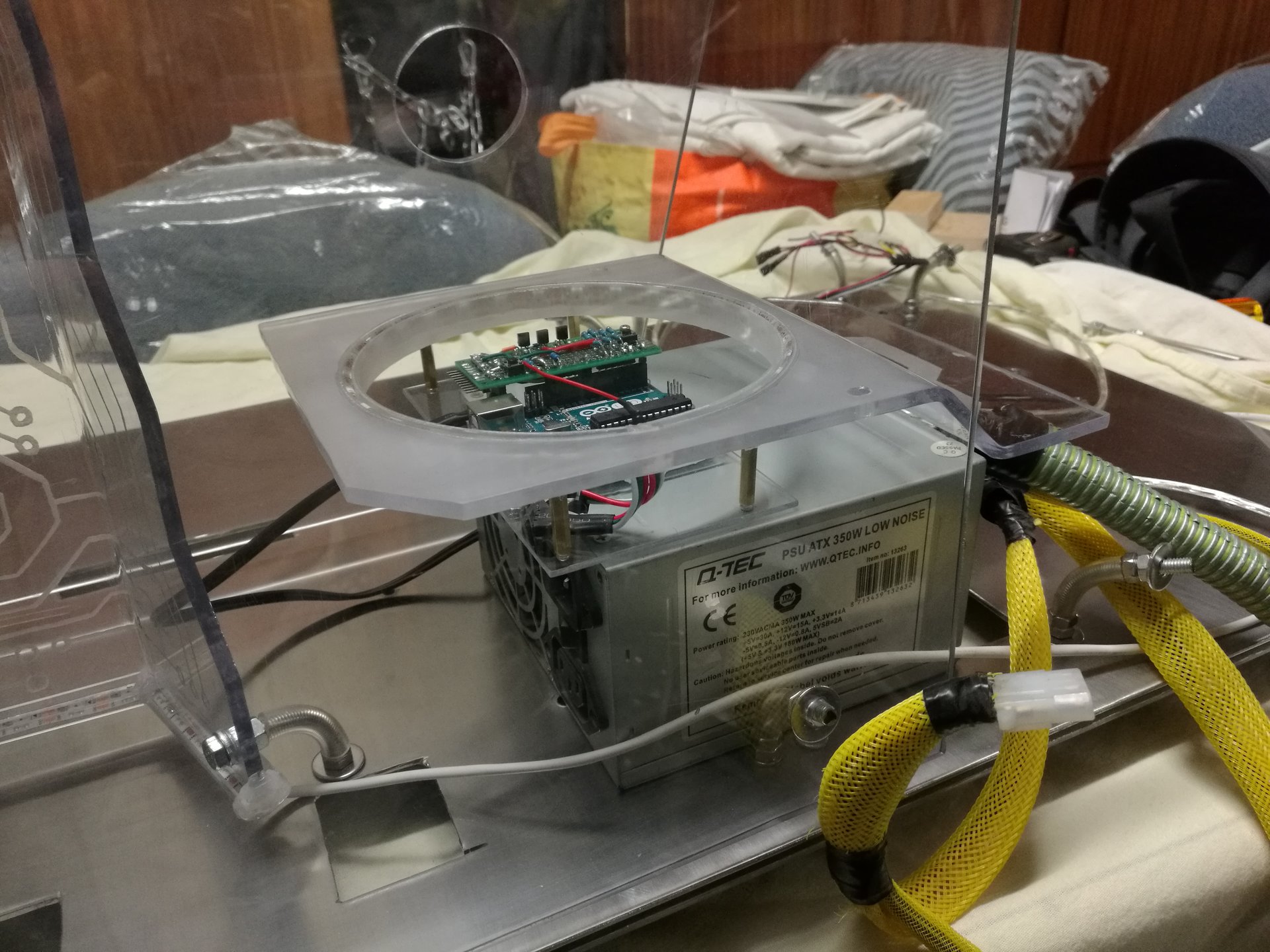


Then I mounted the sensor circuit encasing, the sensor bar, the feedback leds, the PSU cover and the optical drive (and I finished to replace all the nuts and washers with stainless steel ones):


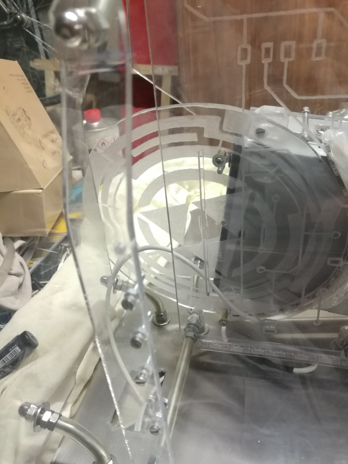
Then I have tested my new mini-projector (1280×800, more than enough for that screen size), and I replaced the projector’s mirror with a smaller one (made in plexiglas, so I’m been able to bend it with heat):
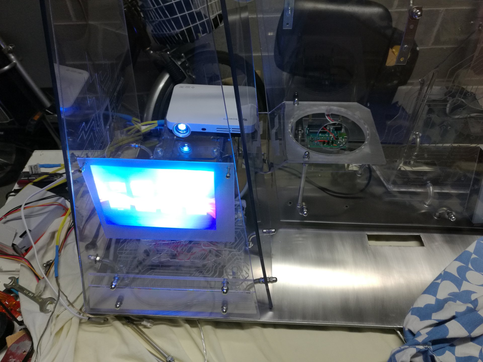
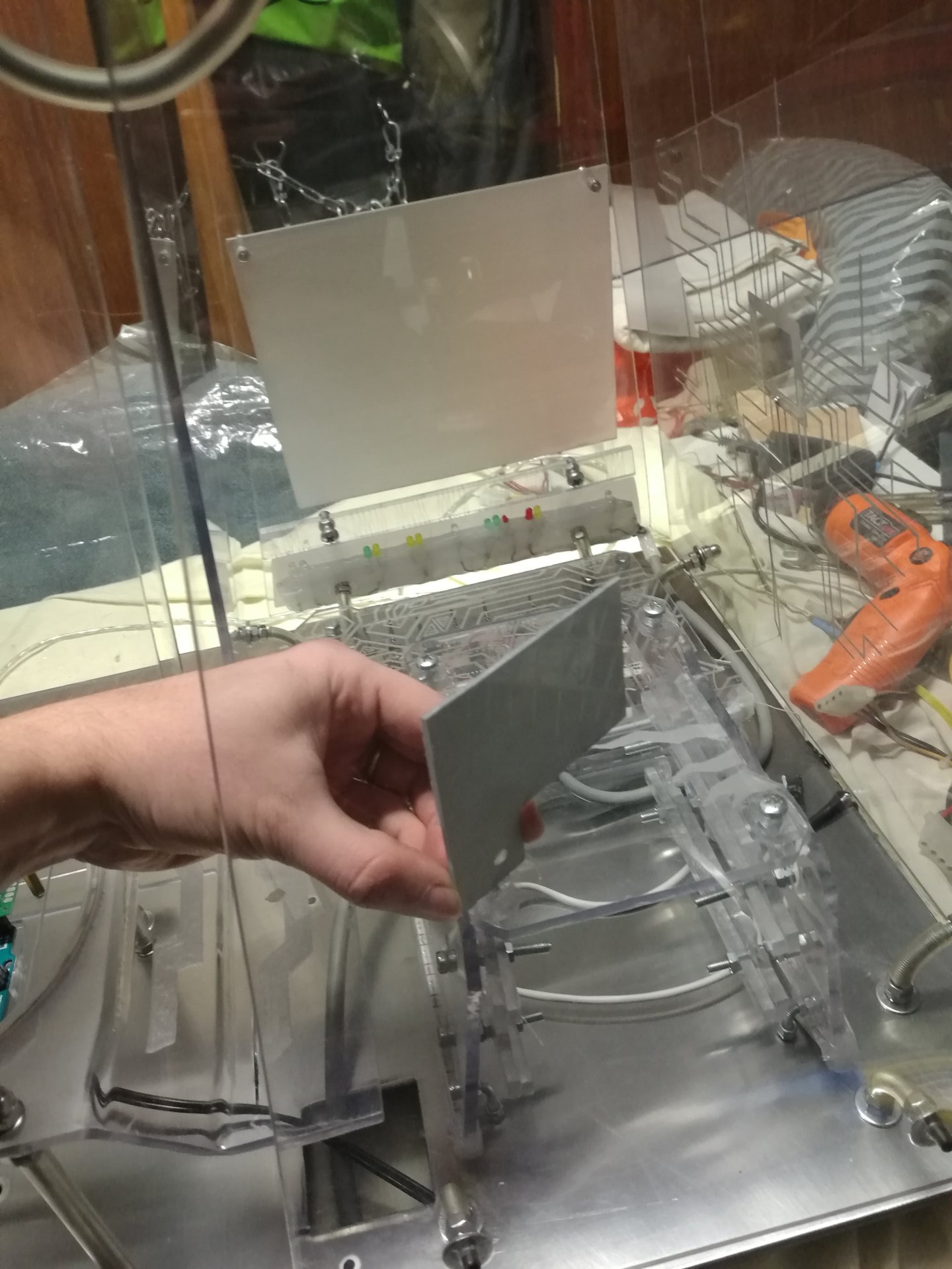
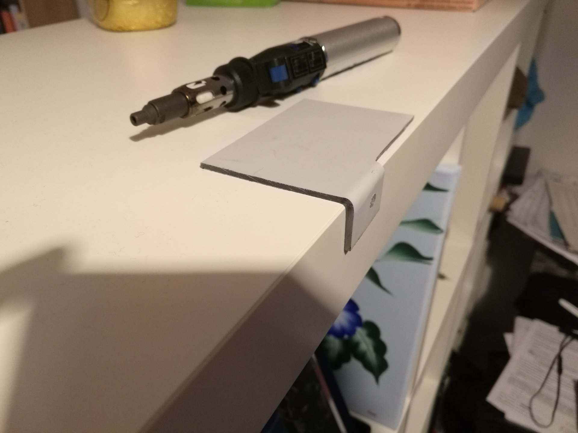
Note: I put these mirror pics in the project log only for documenting this work, but then I have removed the mirror because the new projector I’ve bought has a lot wider projection cone than the old one, so I put the projector directly behind the projection screen (above the hard disks)
Meanwhile I was working on the software too:
I have programmed a Java application (that I called KernelController 😀 ) for the PC, that communicates bidirectionally with Arduino using the serial port.
The application has these functions:
– it can query Arduino to get the list of the lighting states that I have programmed (including some monochromatic, polychromatic, animated and mixed states)
– it can select the desired lighting state from the list
– it shows the current selected state (even if it is selected directly by the proximity or touch sensors)
– it launches an appropriate animation on the projector, when some lighting state is selected. For example it launches a red alarm signal animation when selecting the pulsing red state (this function can be disabled, because it can be annoying in some moments)
In these videos I’m testing some functions of the application: changing lighting states and starting animations on the projector: