This is the video of all the features of the mod (in particular all the animations and the moving parts)!
NOTE: the video has english subtitles, that can be activated from the youtube interface
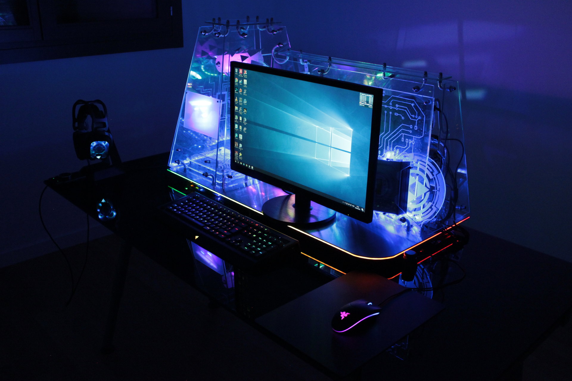
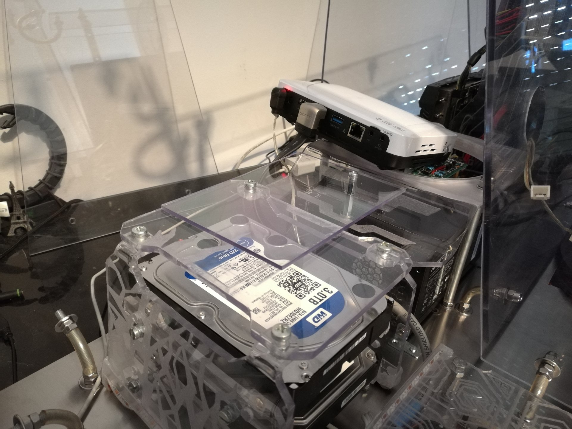
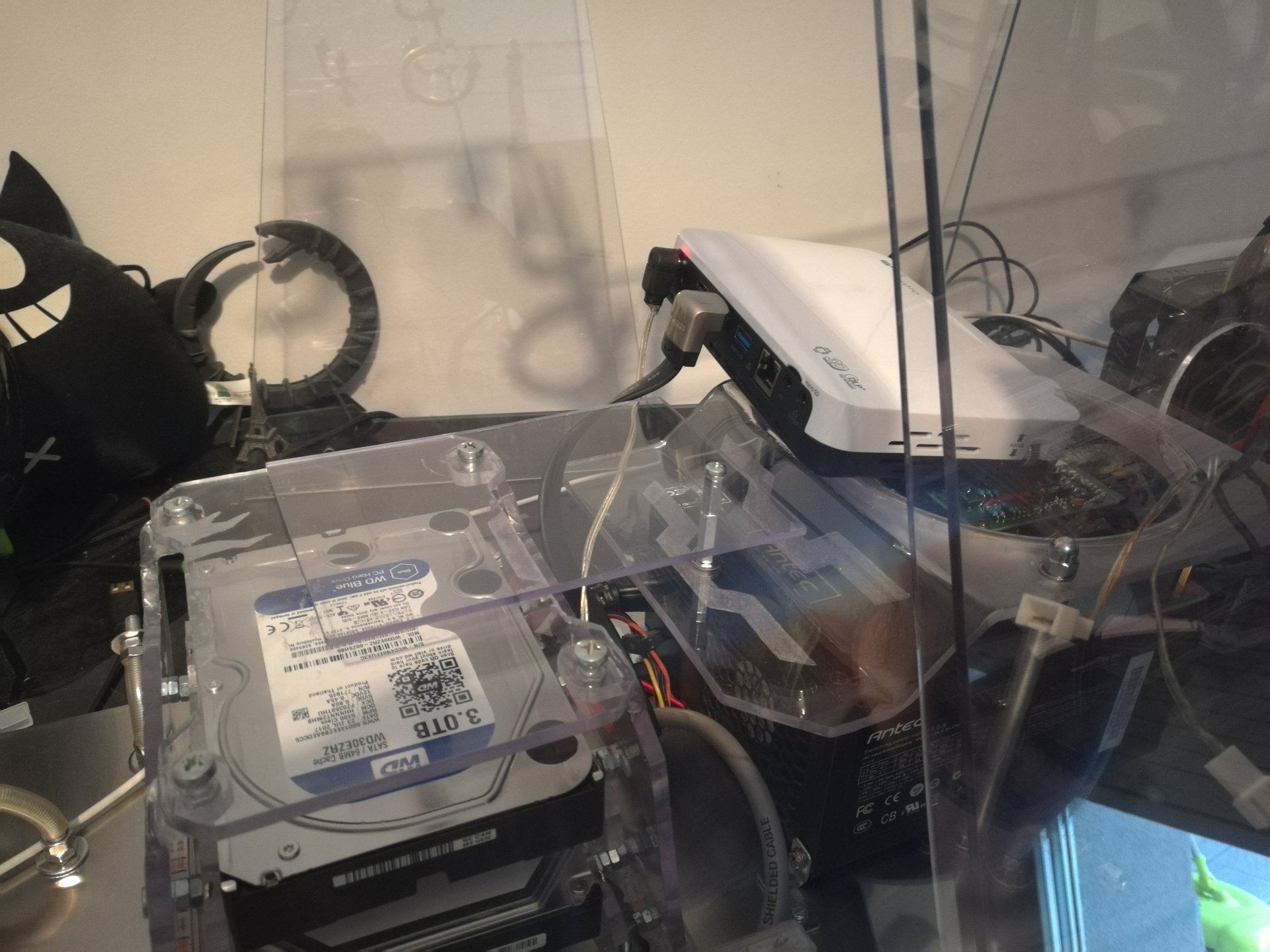
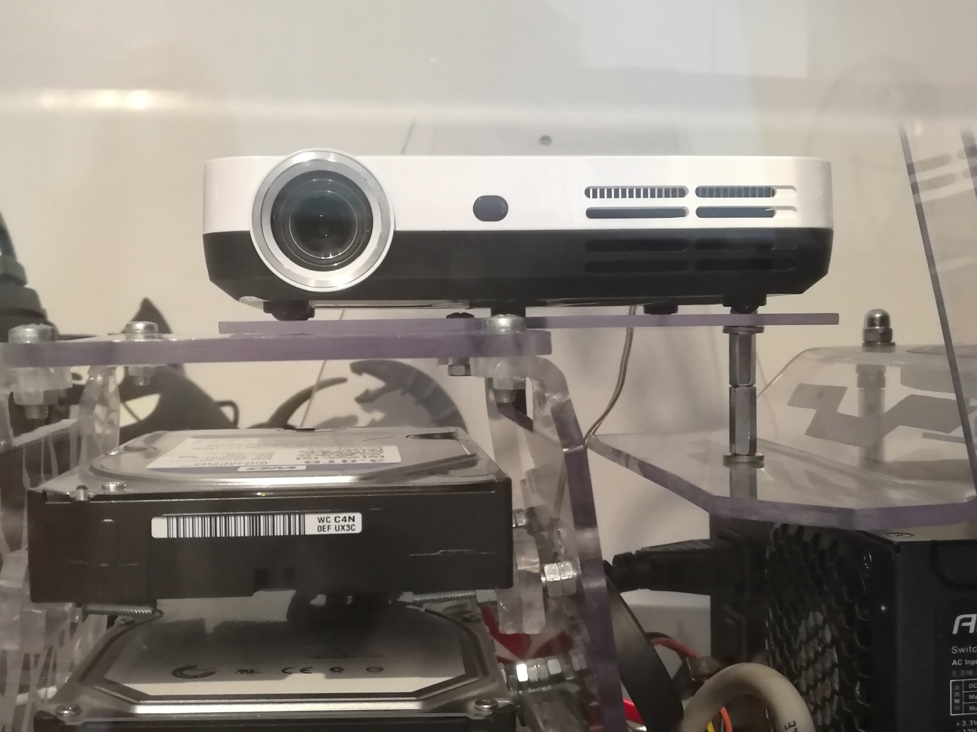
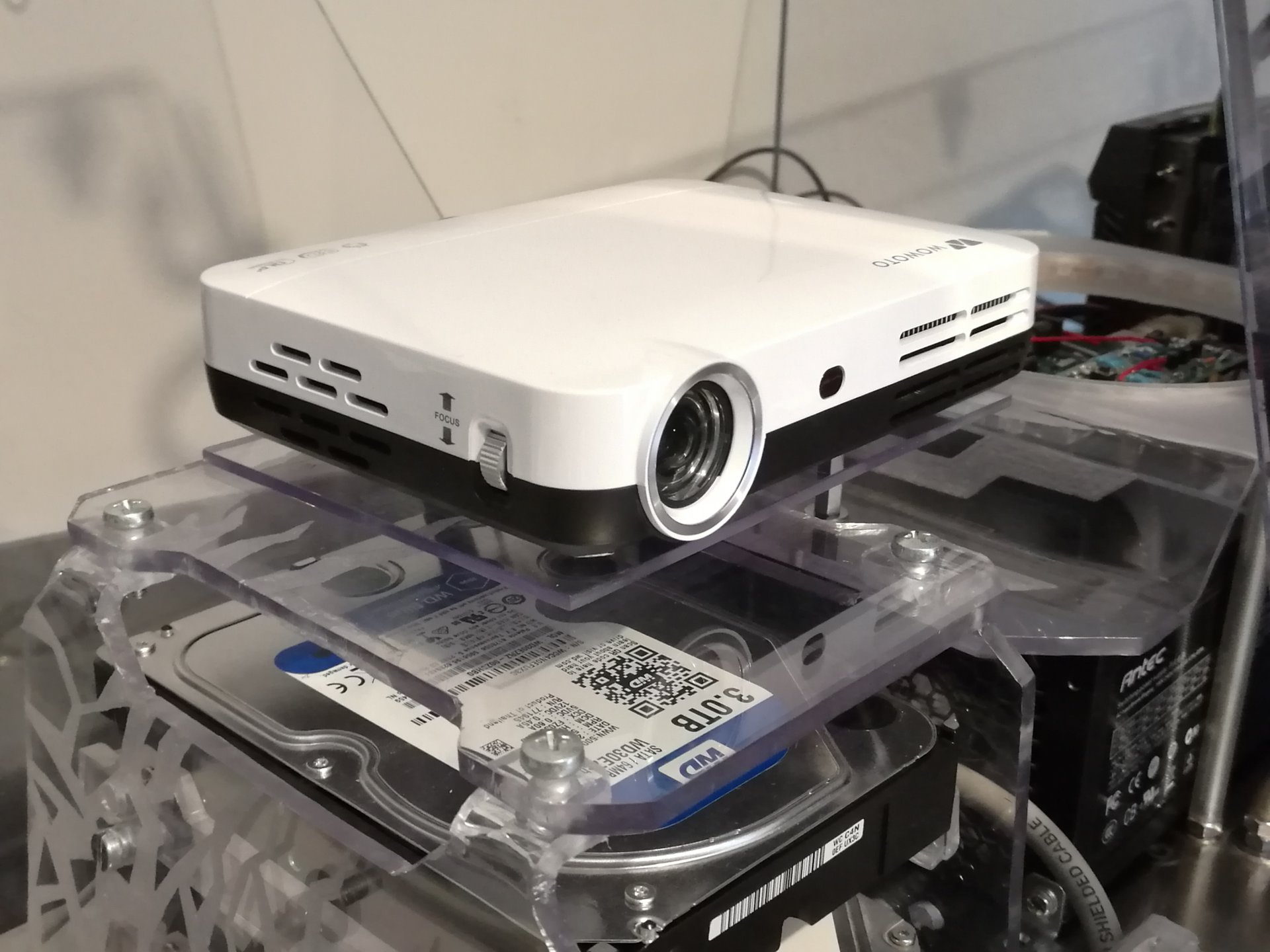
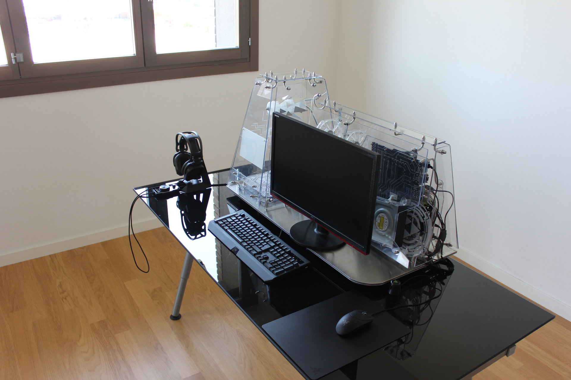
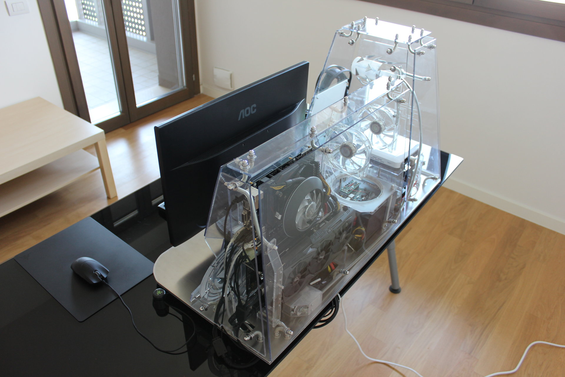
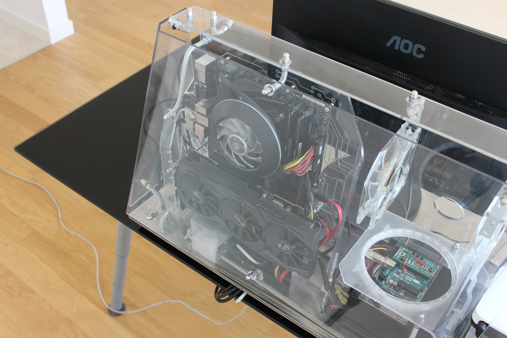
And these are all the pics, divided by lighting state:
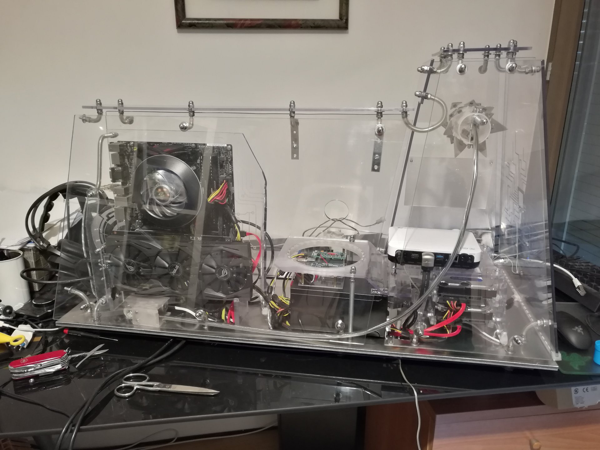
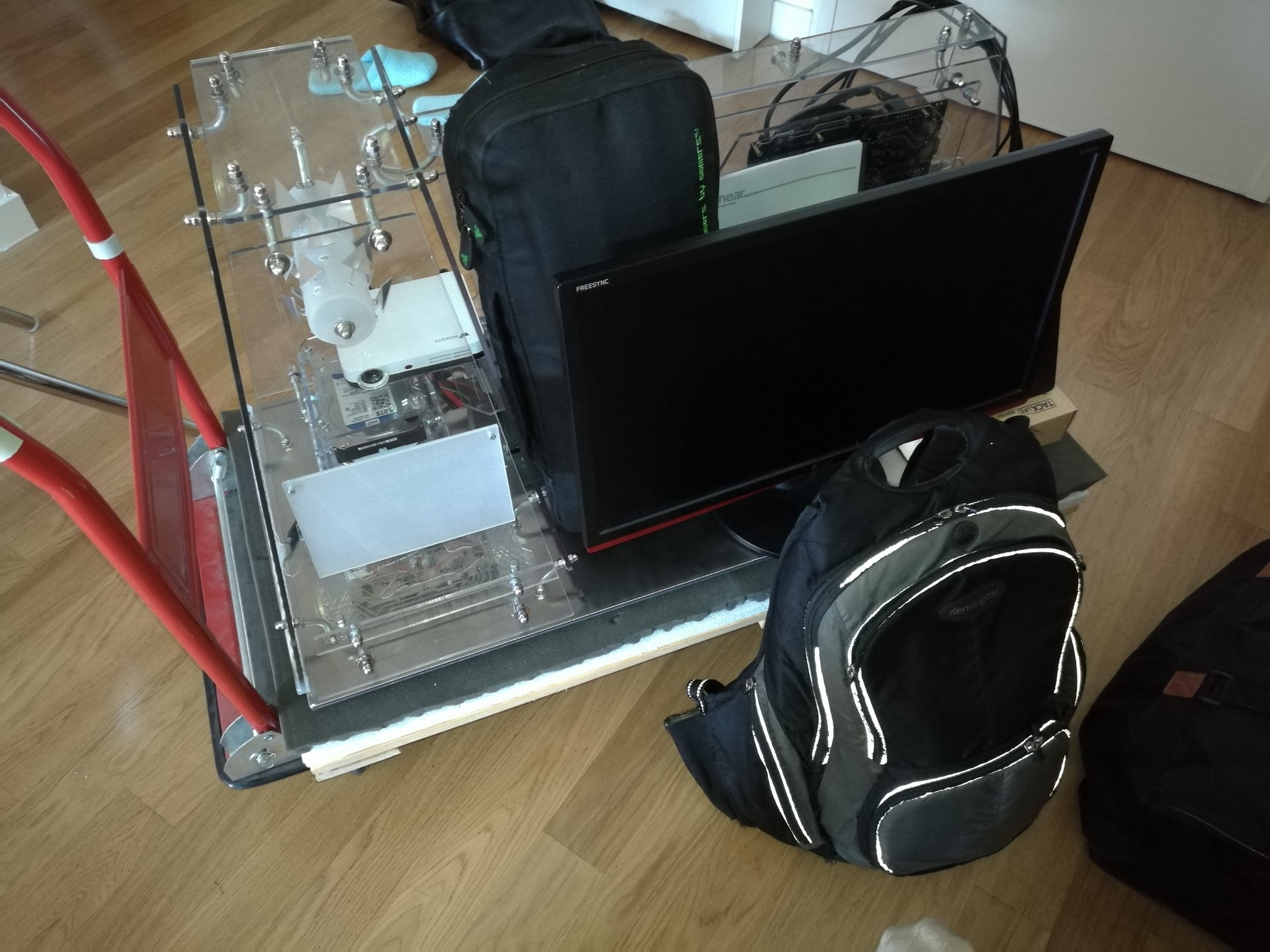
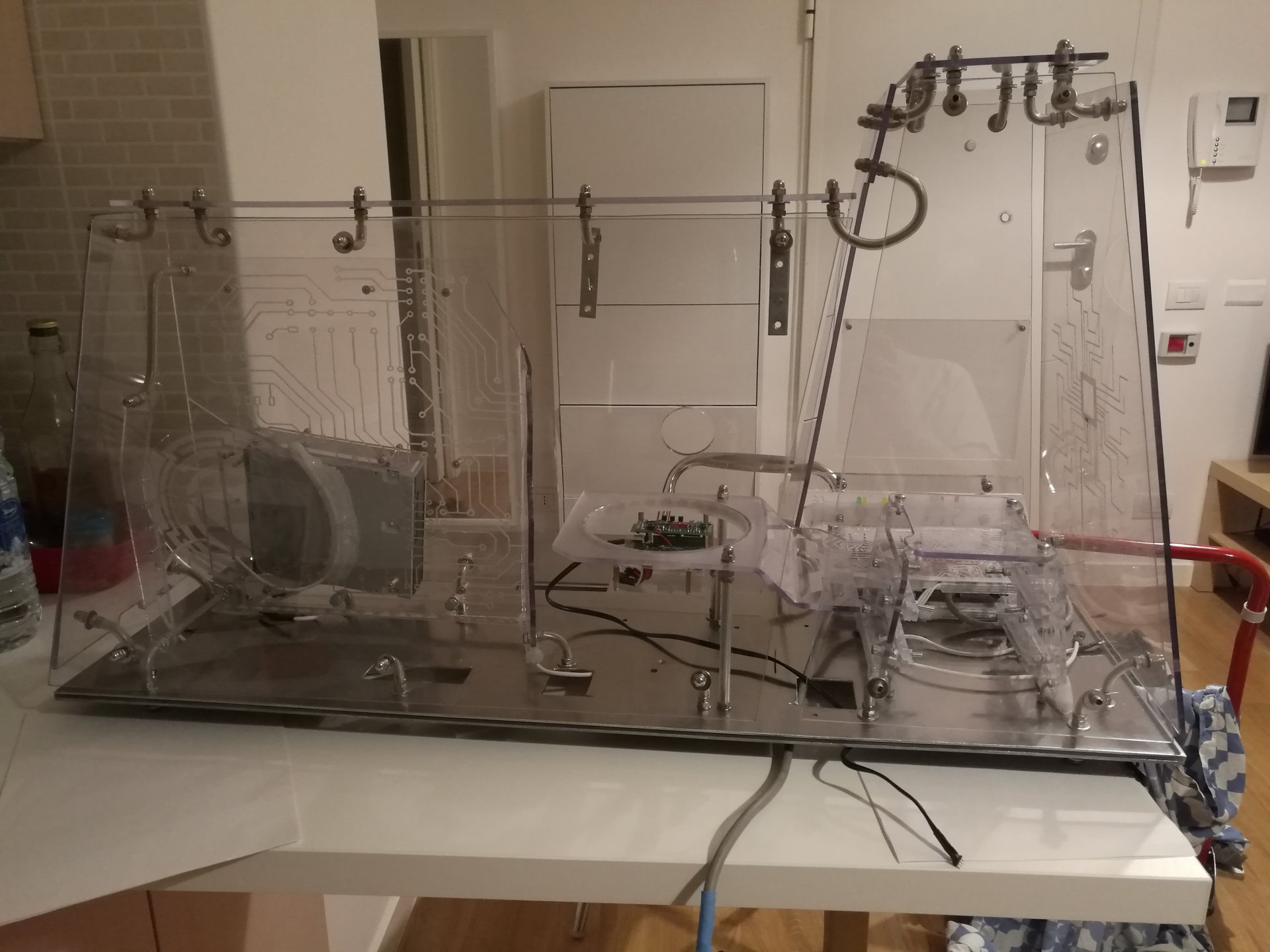
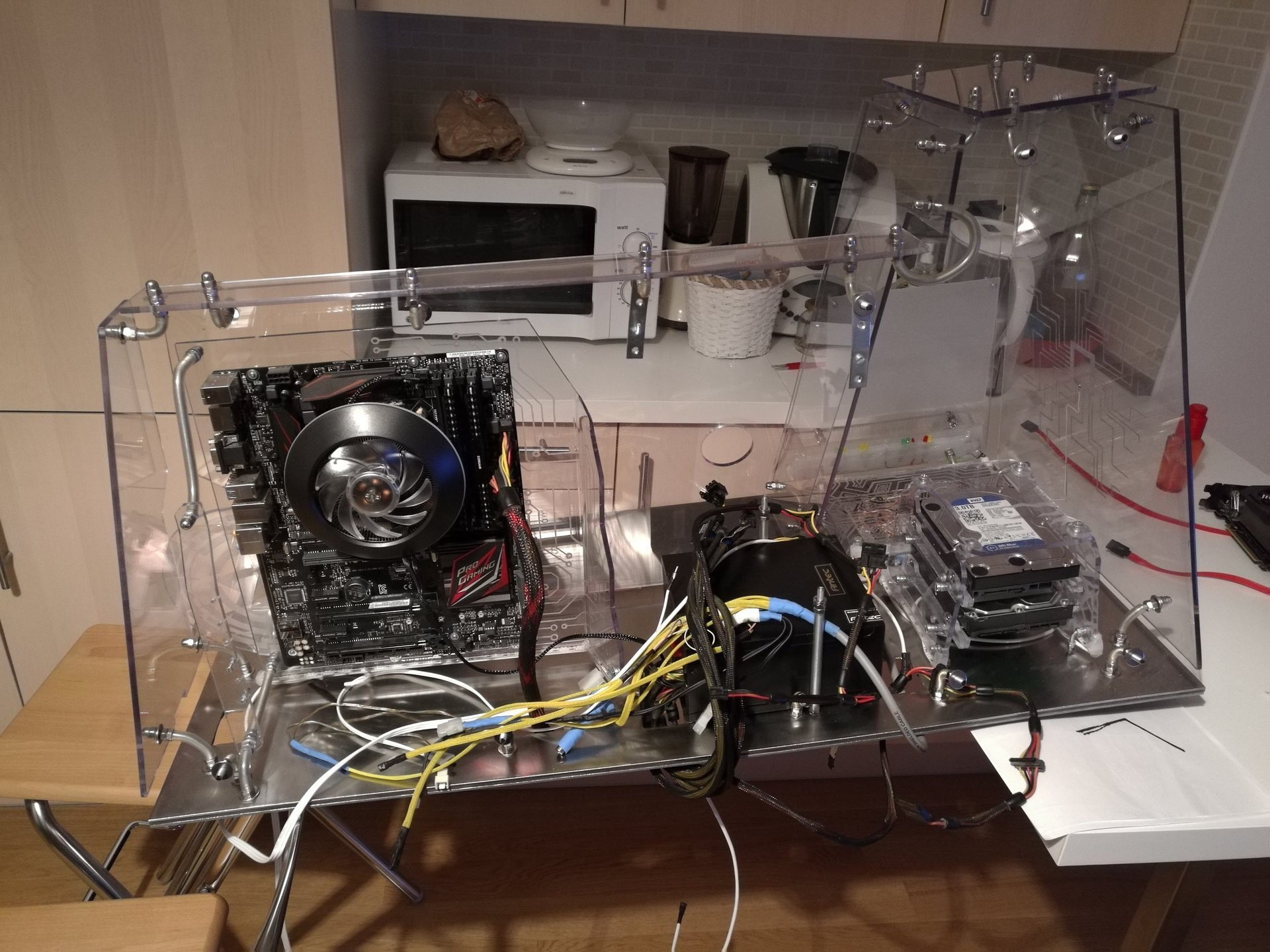
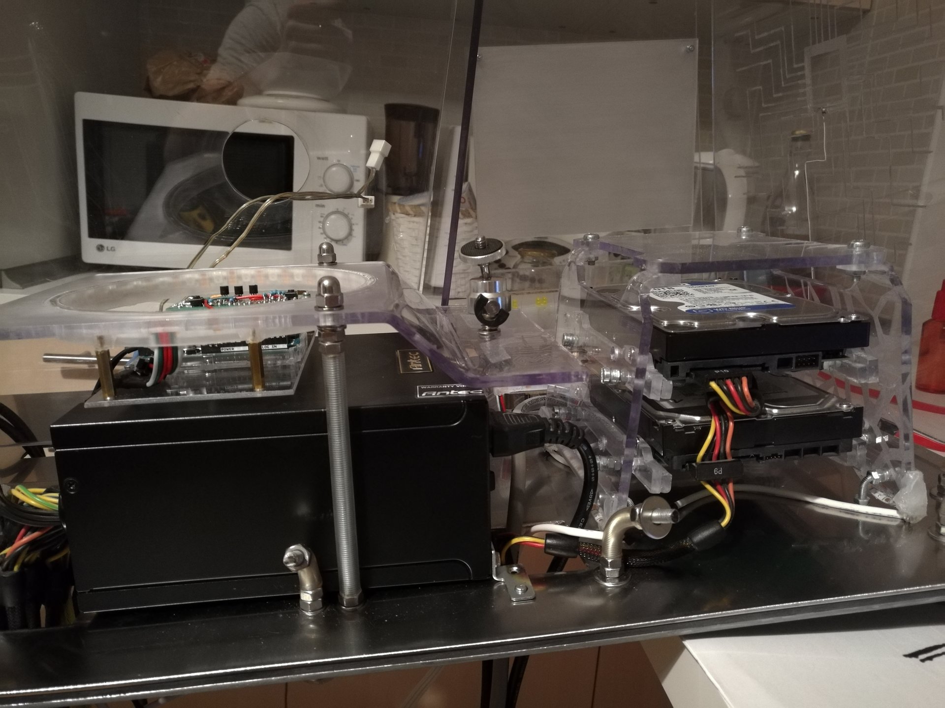
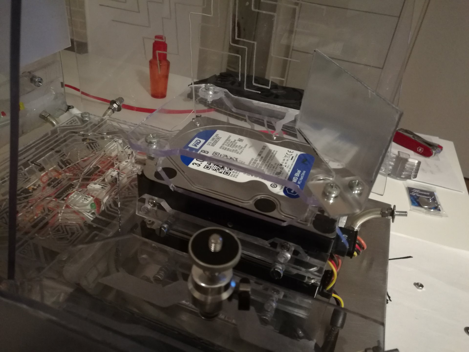
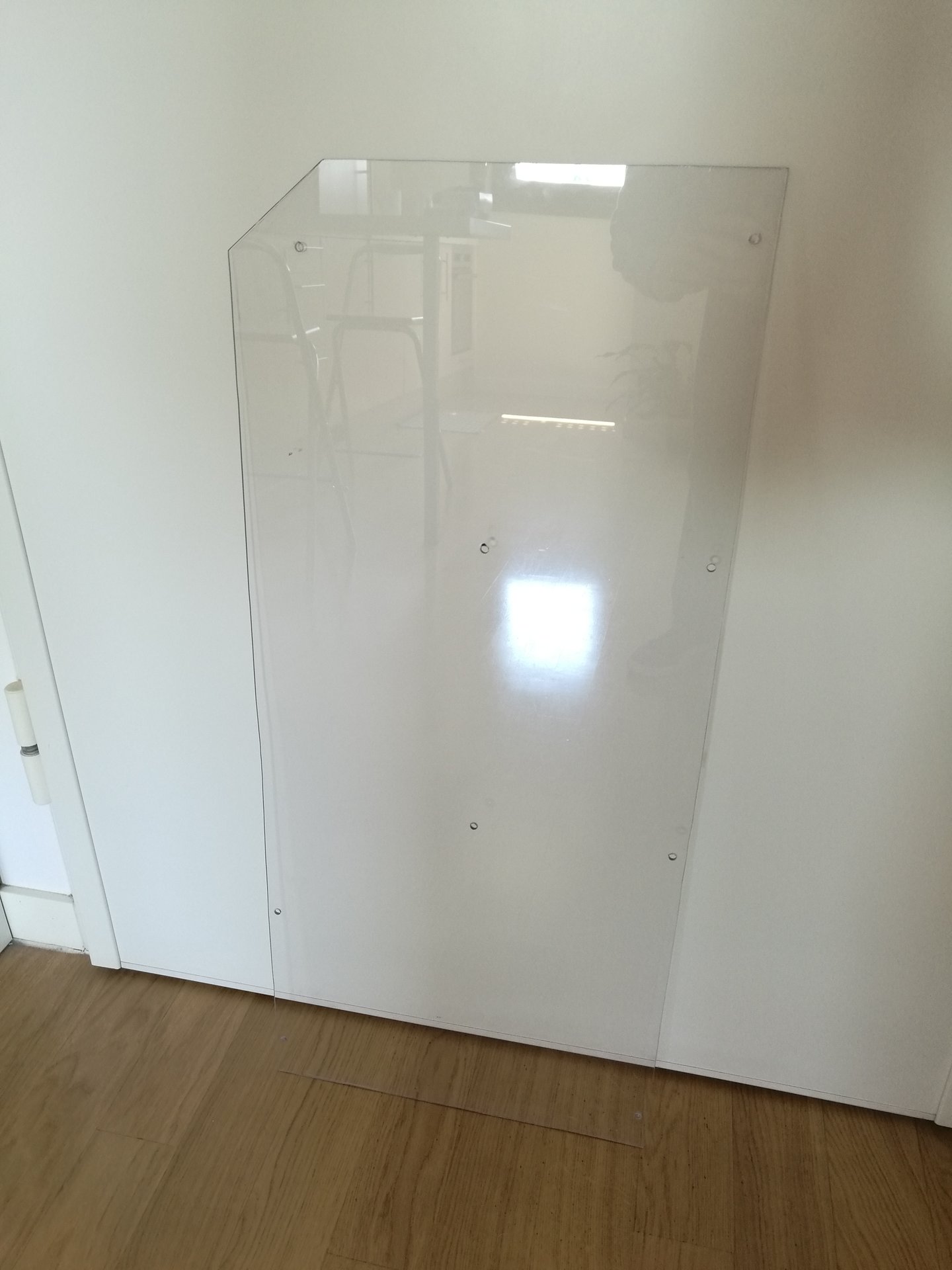
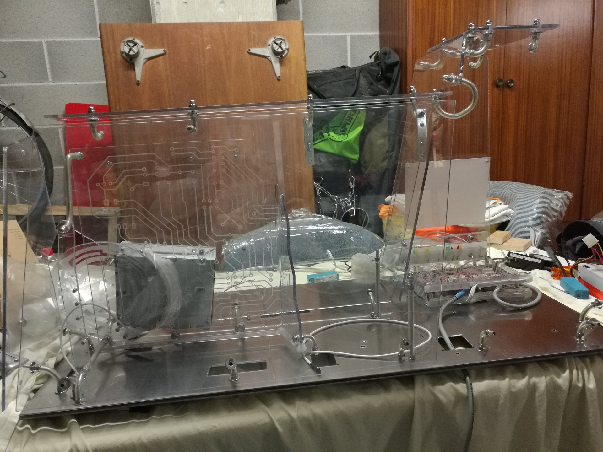
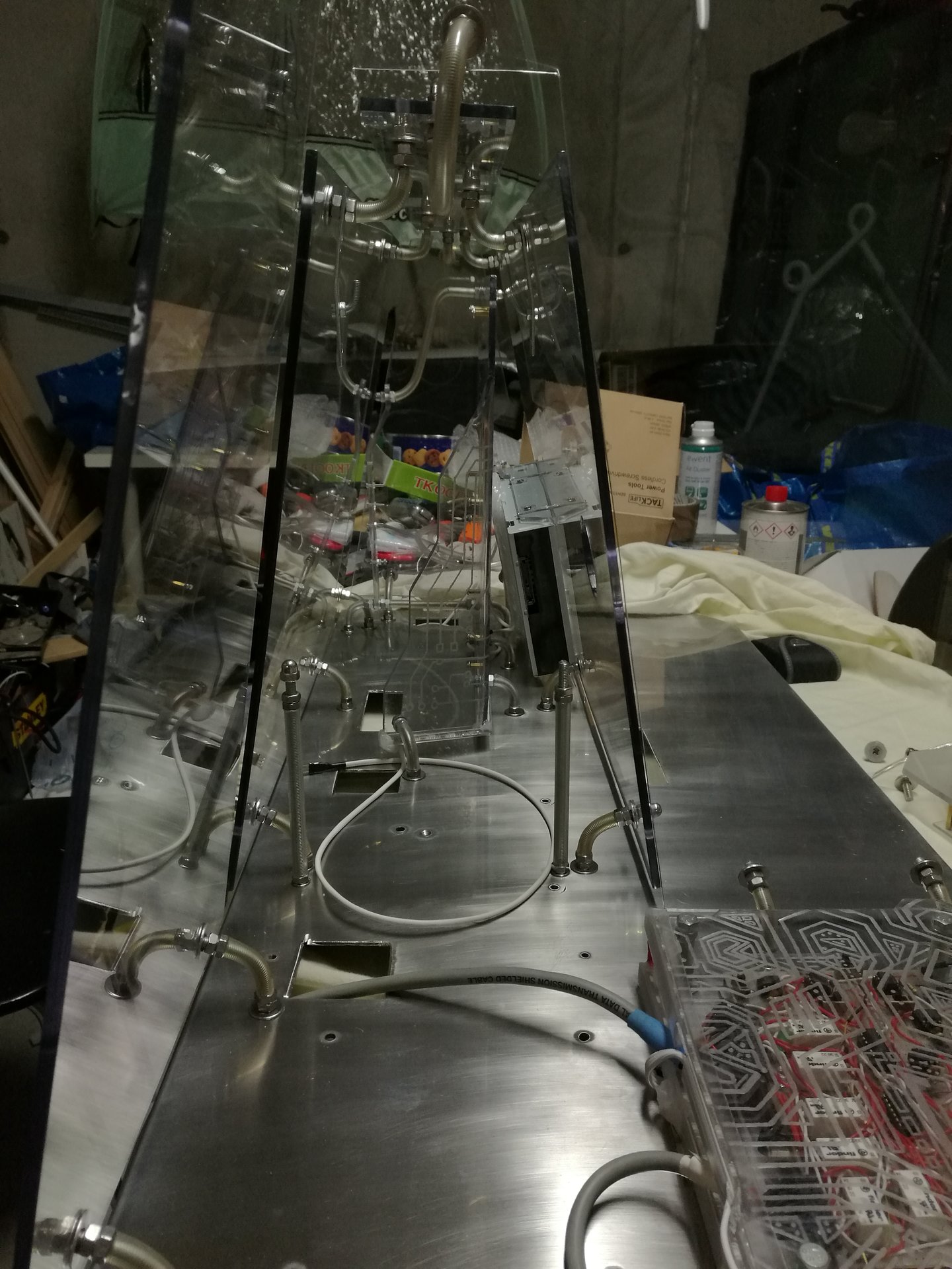
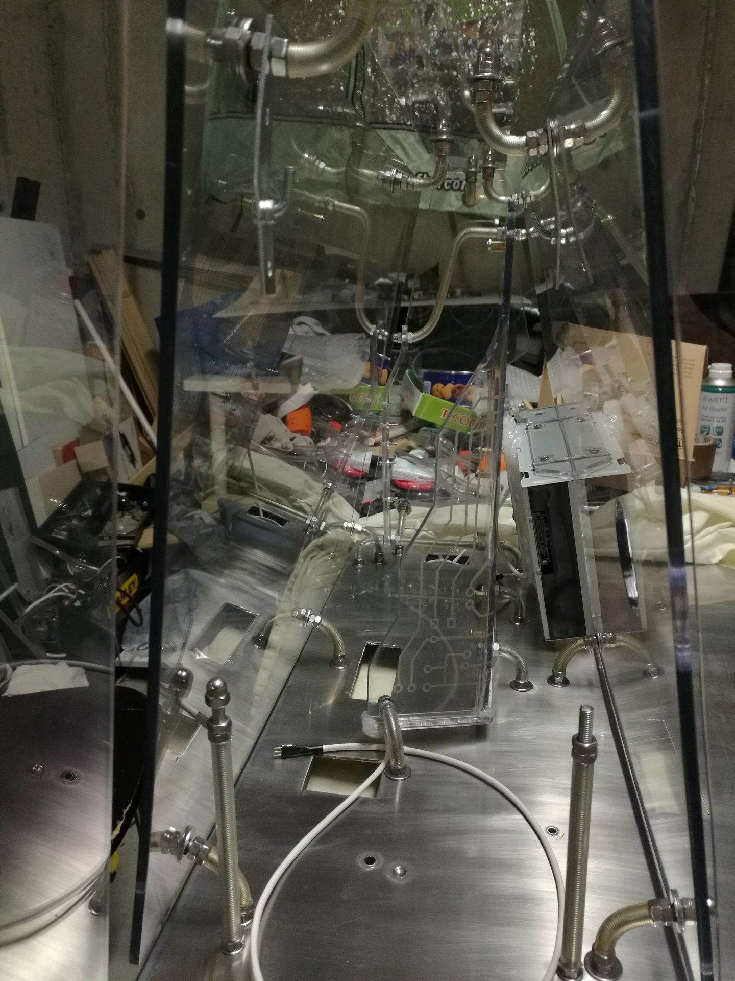
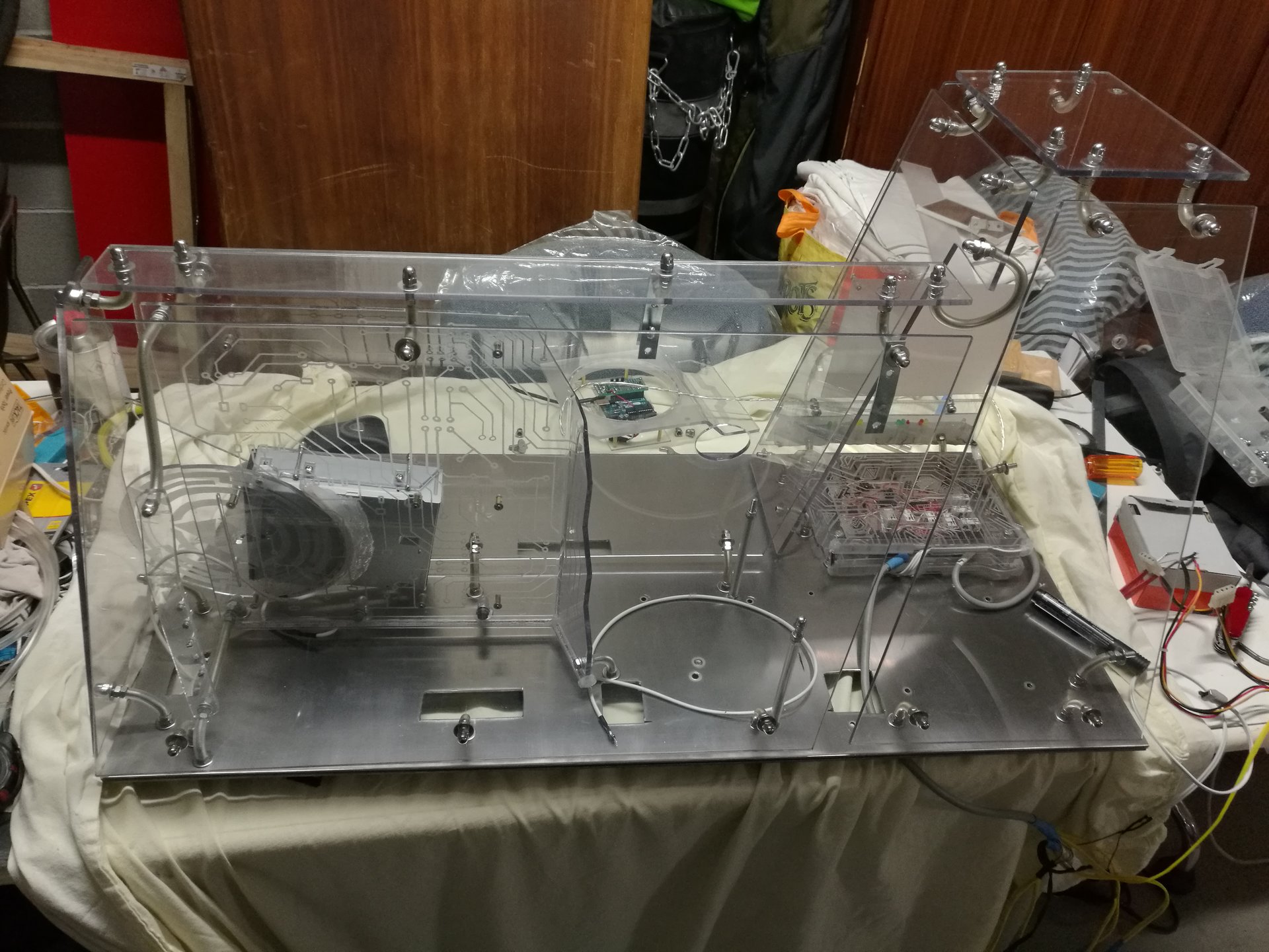
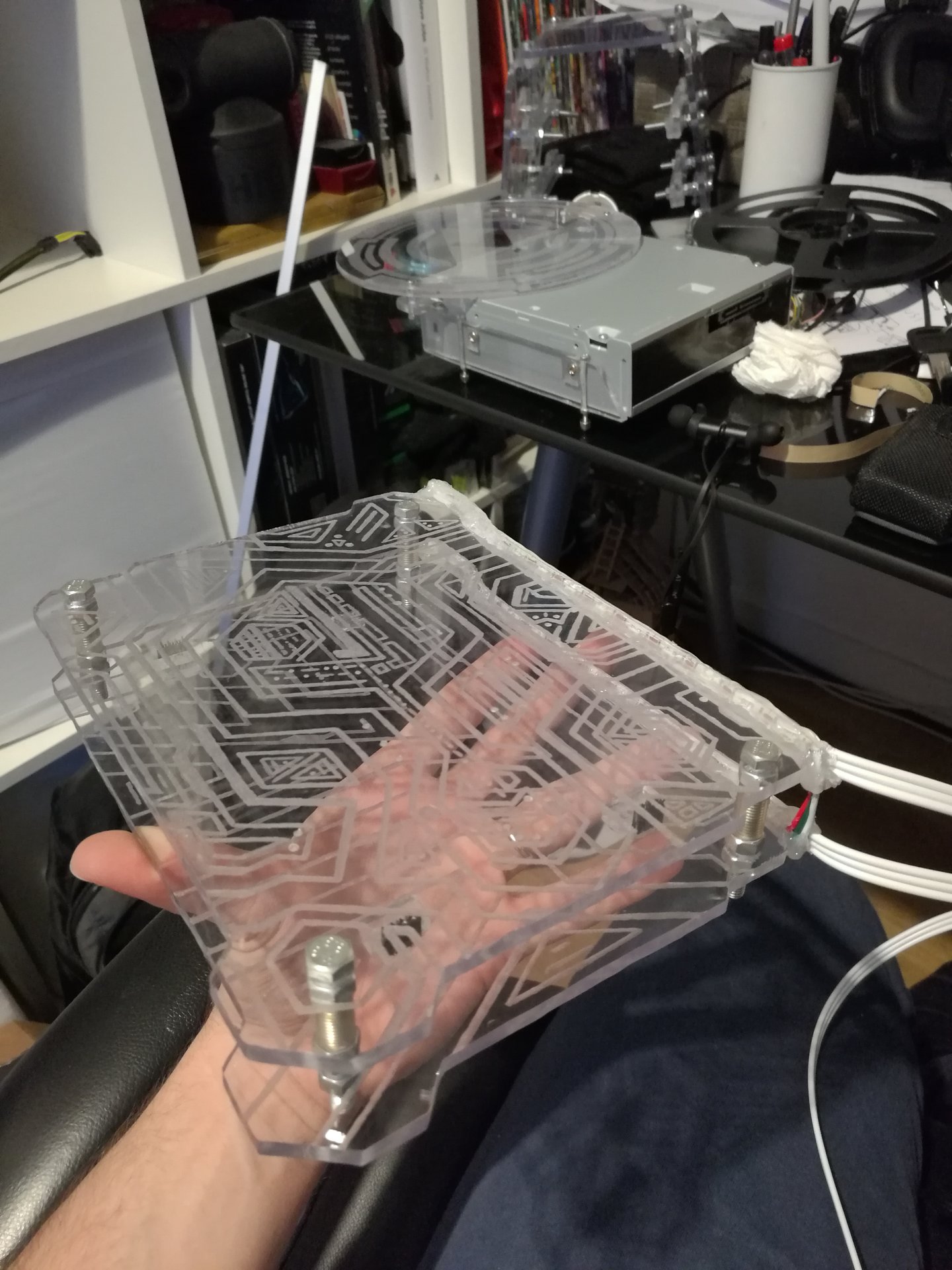
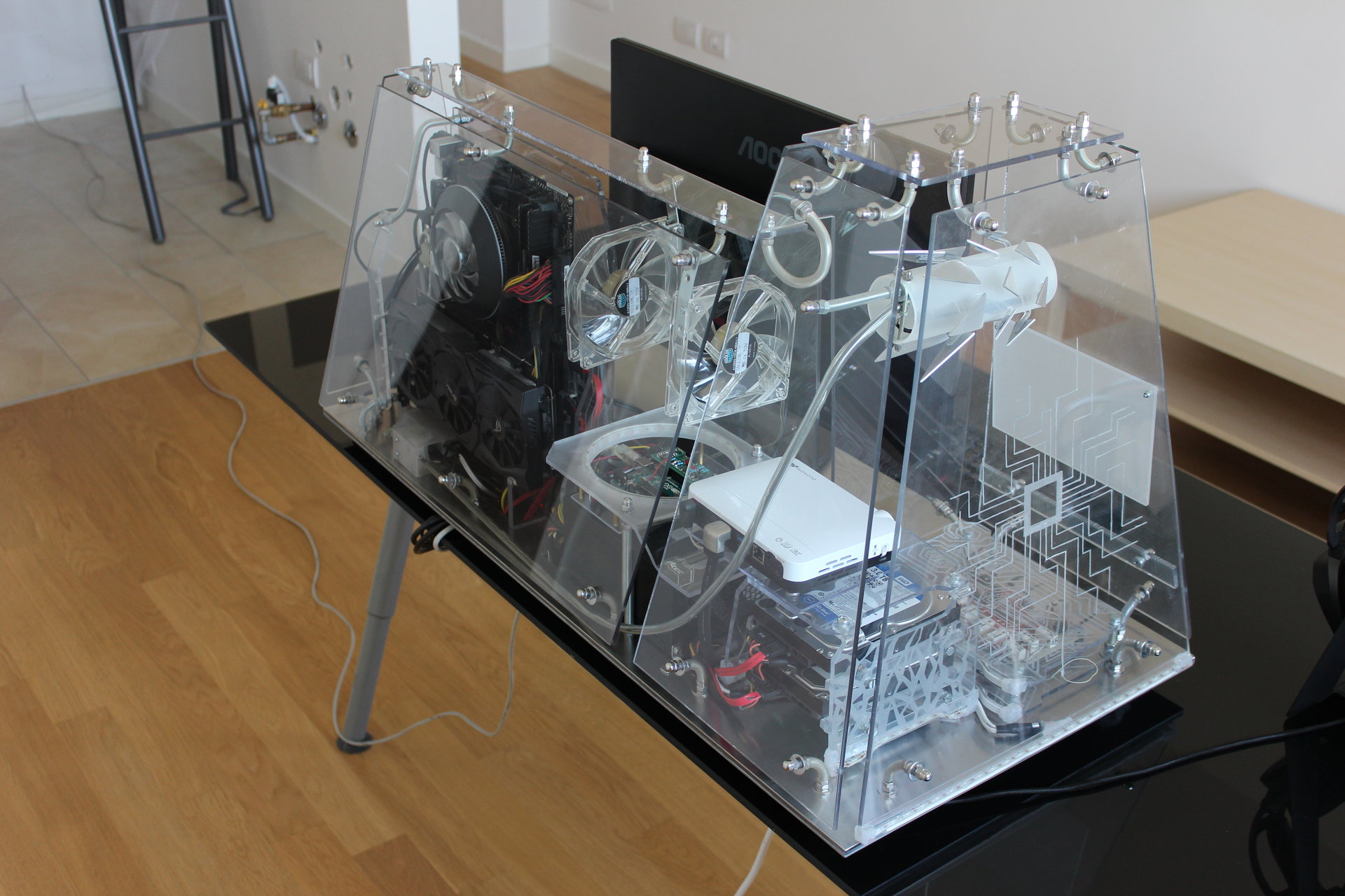
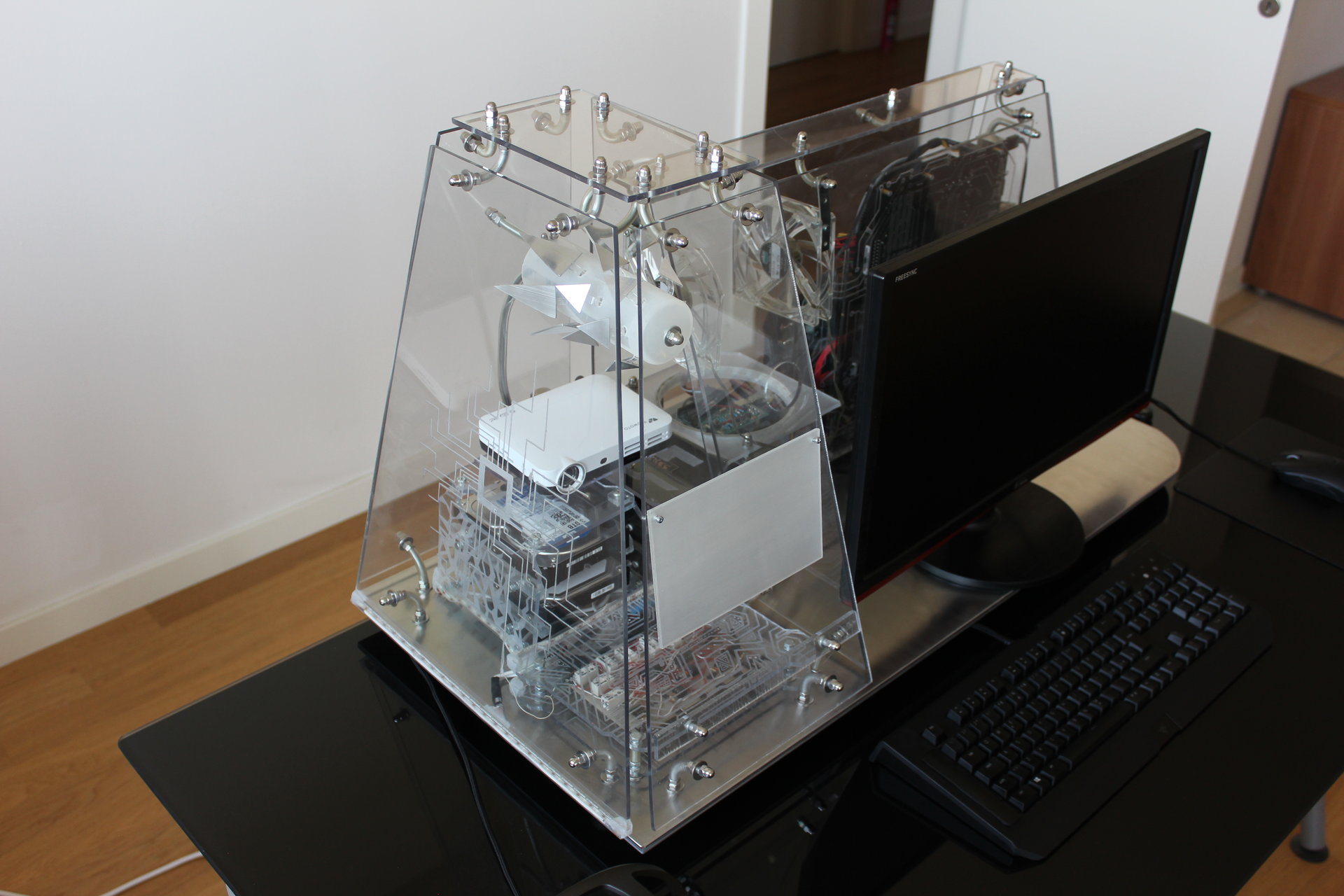
The powered off PC:
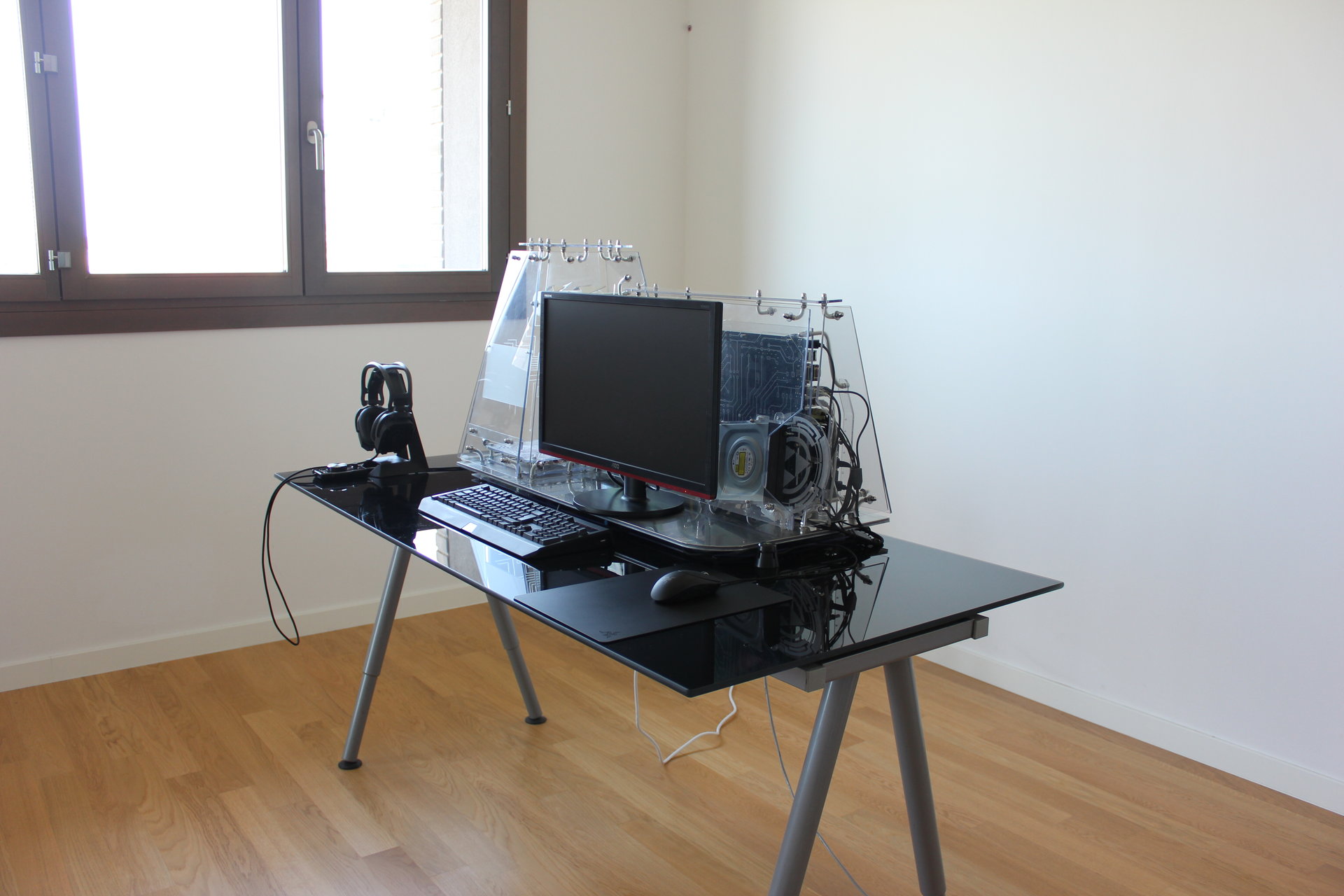
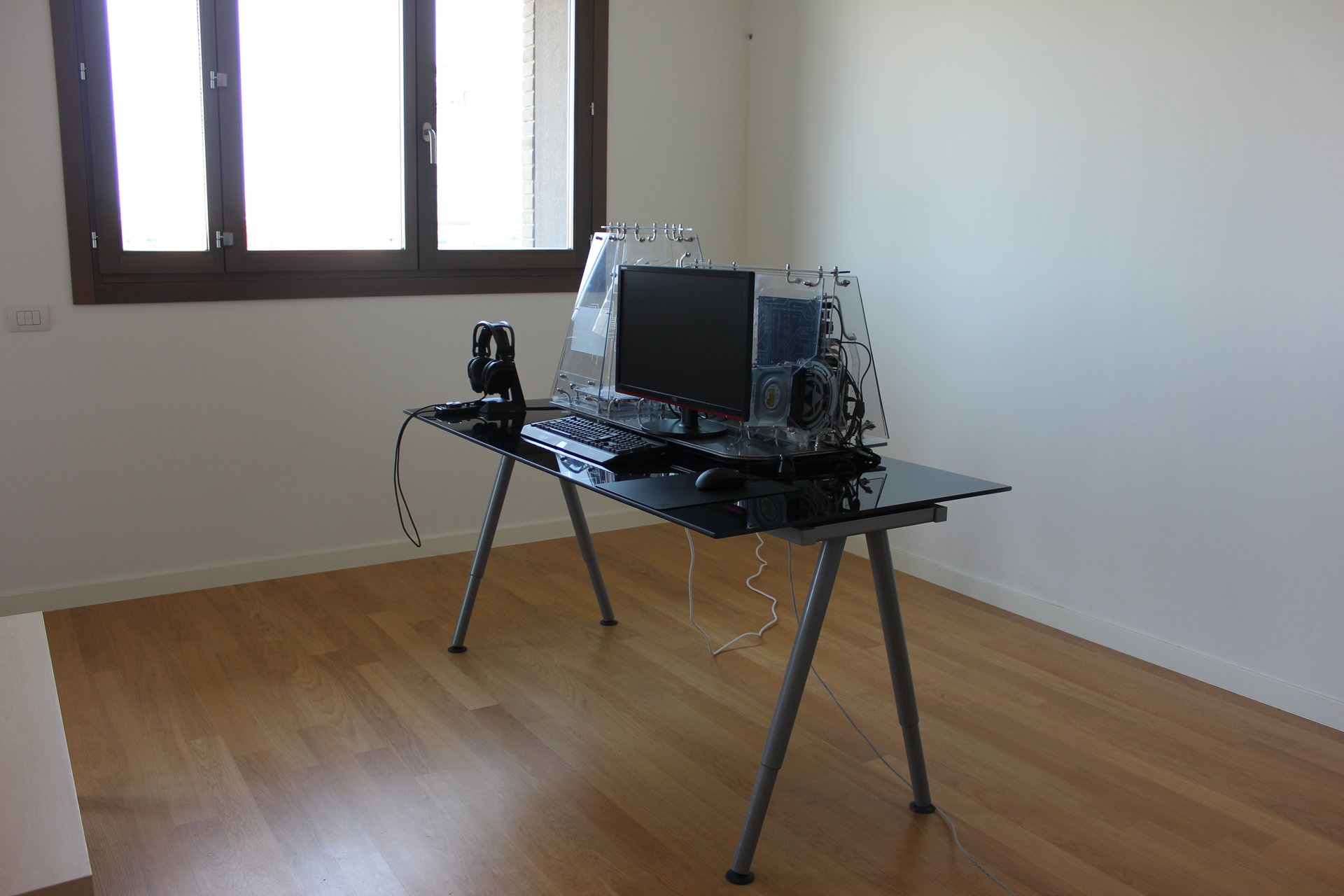
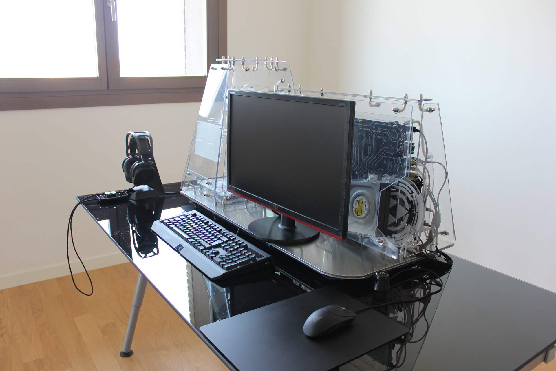
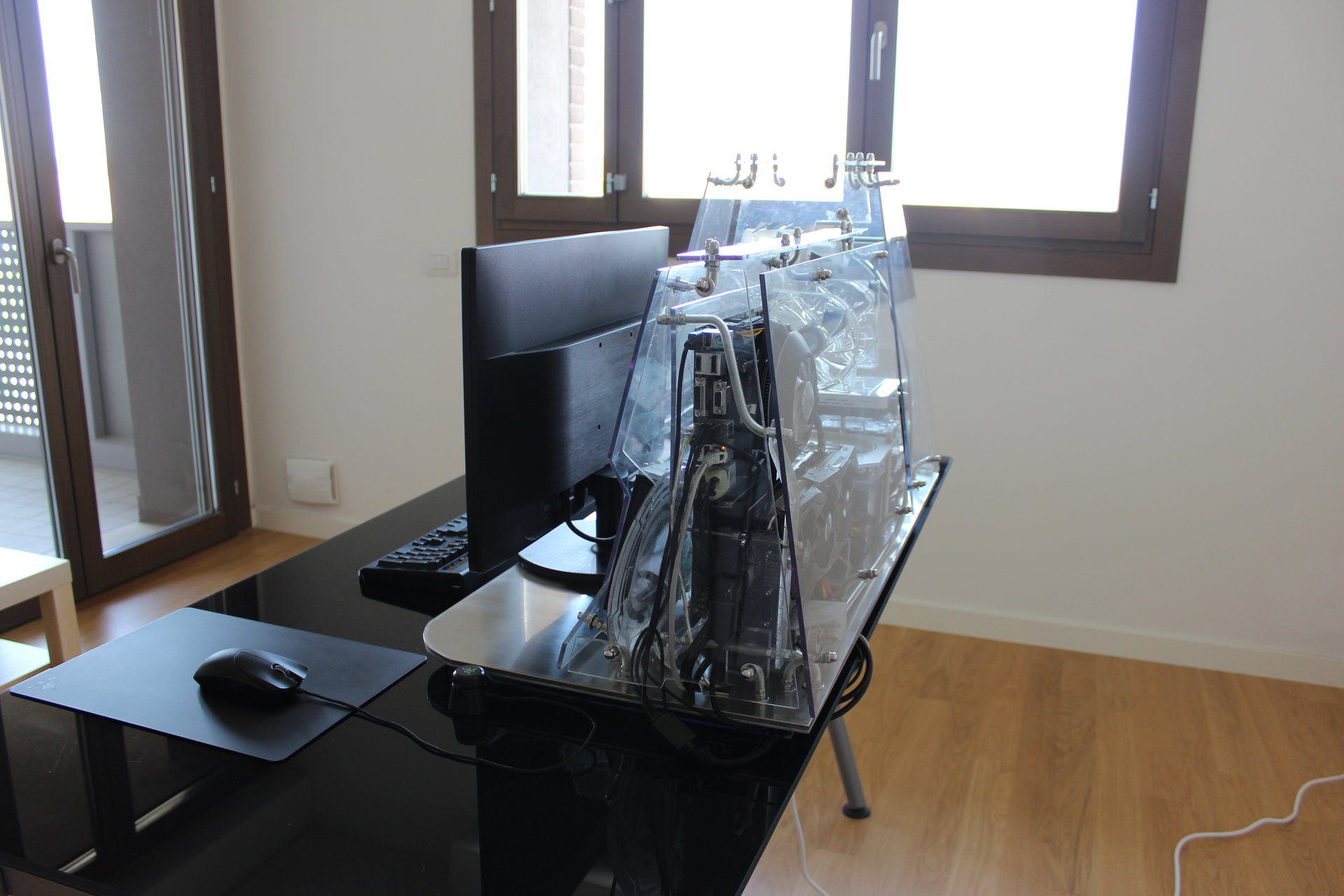
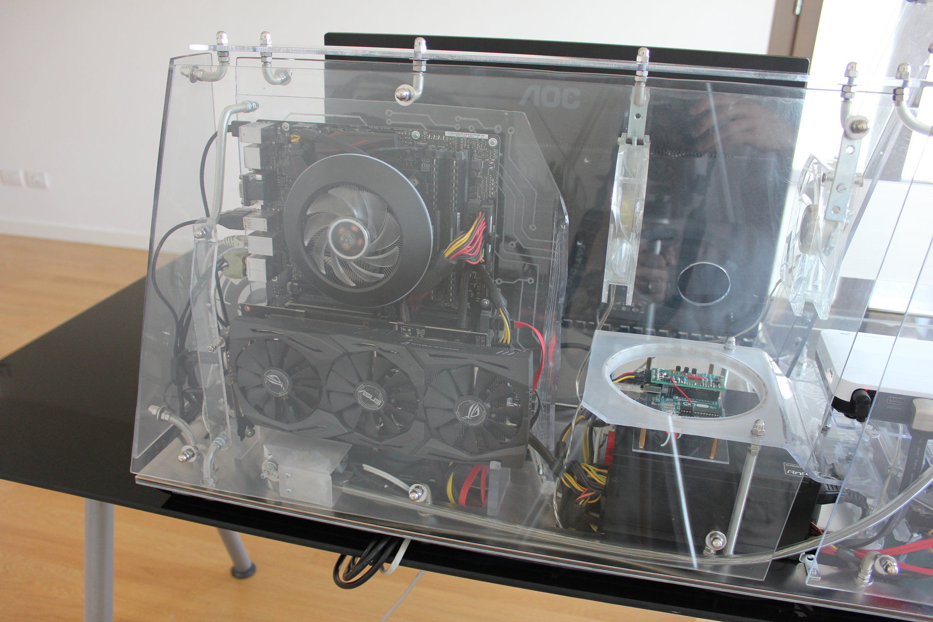
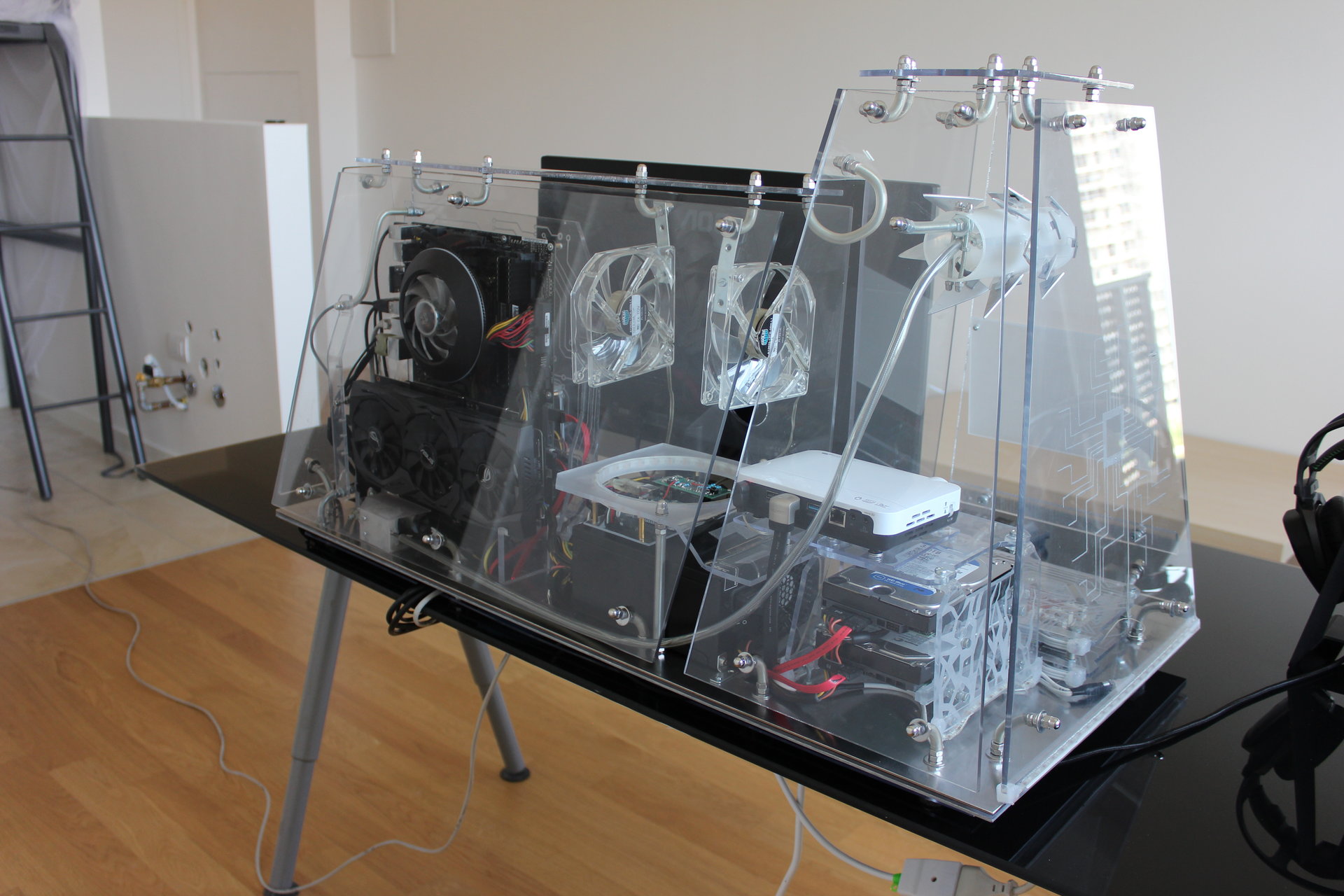

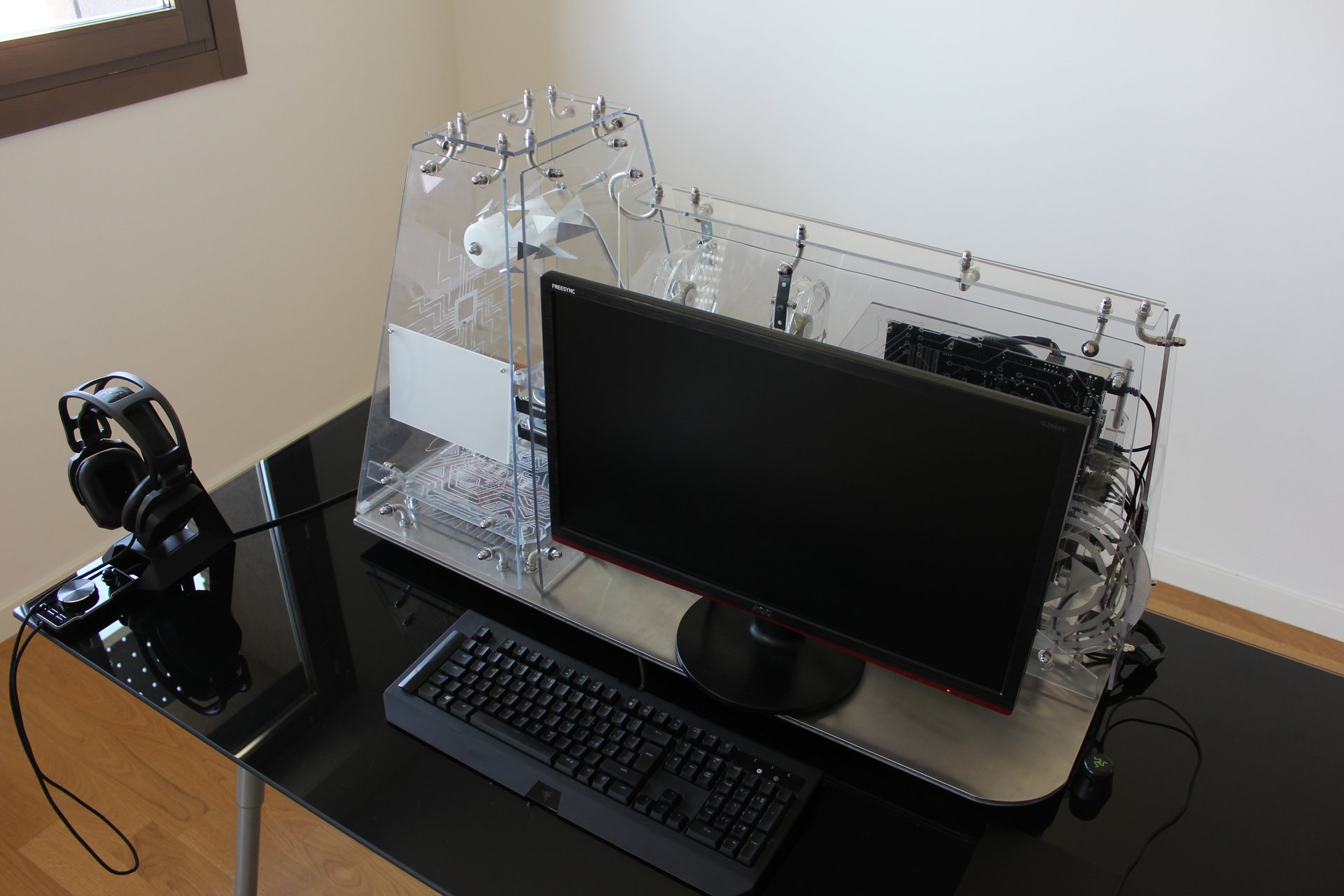

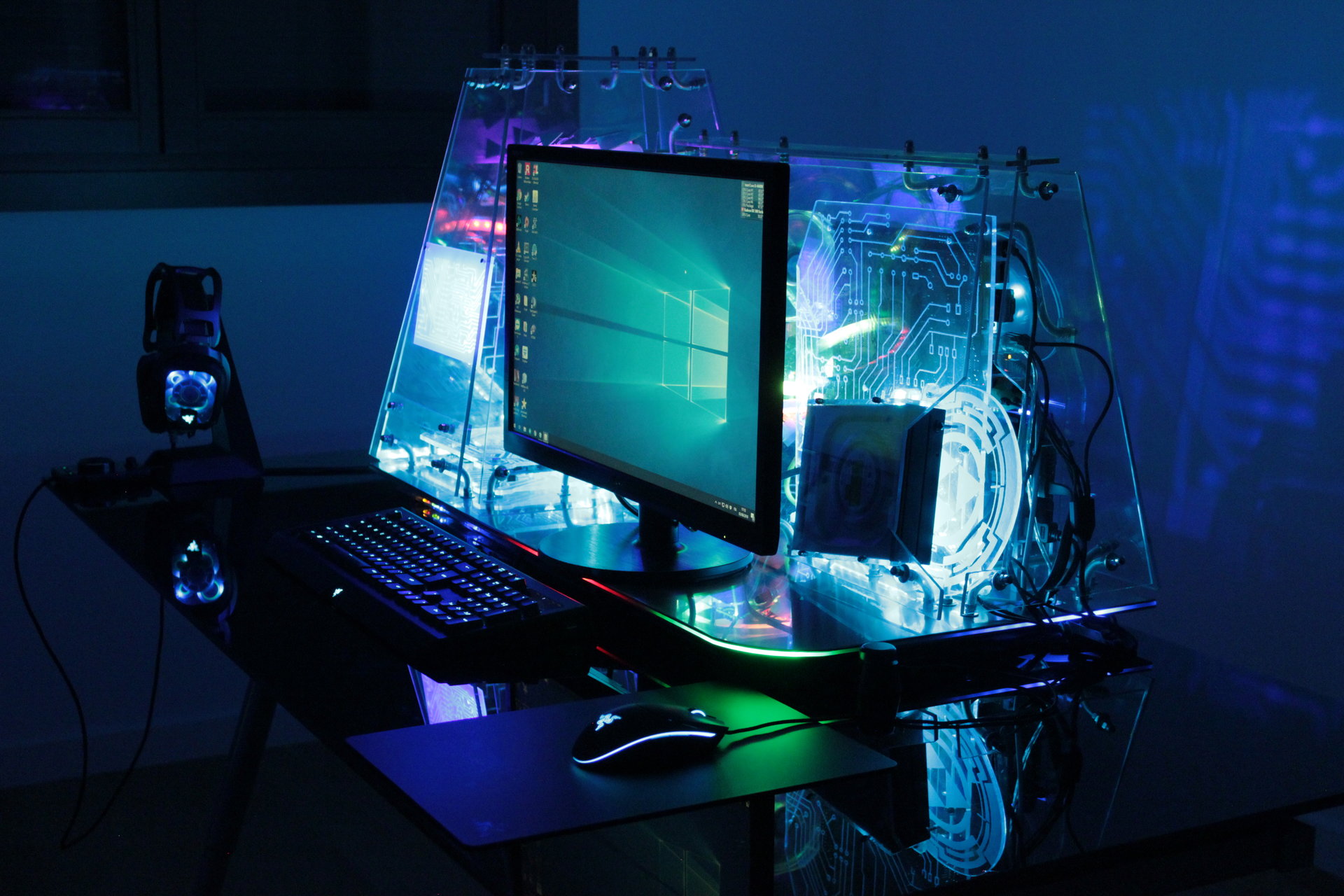
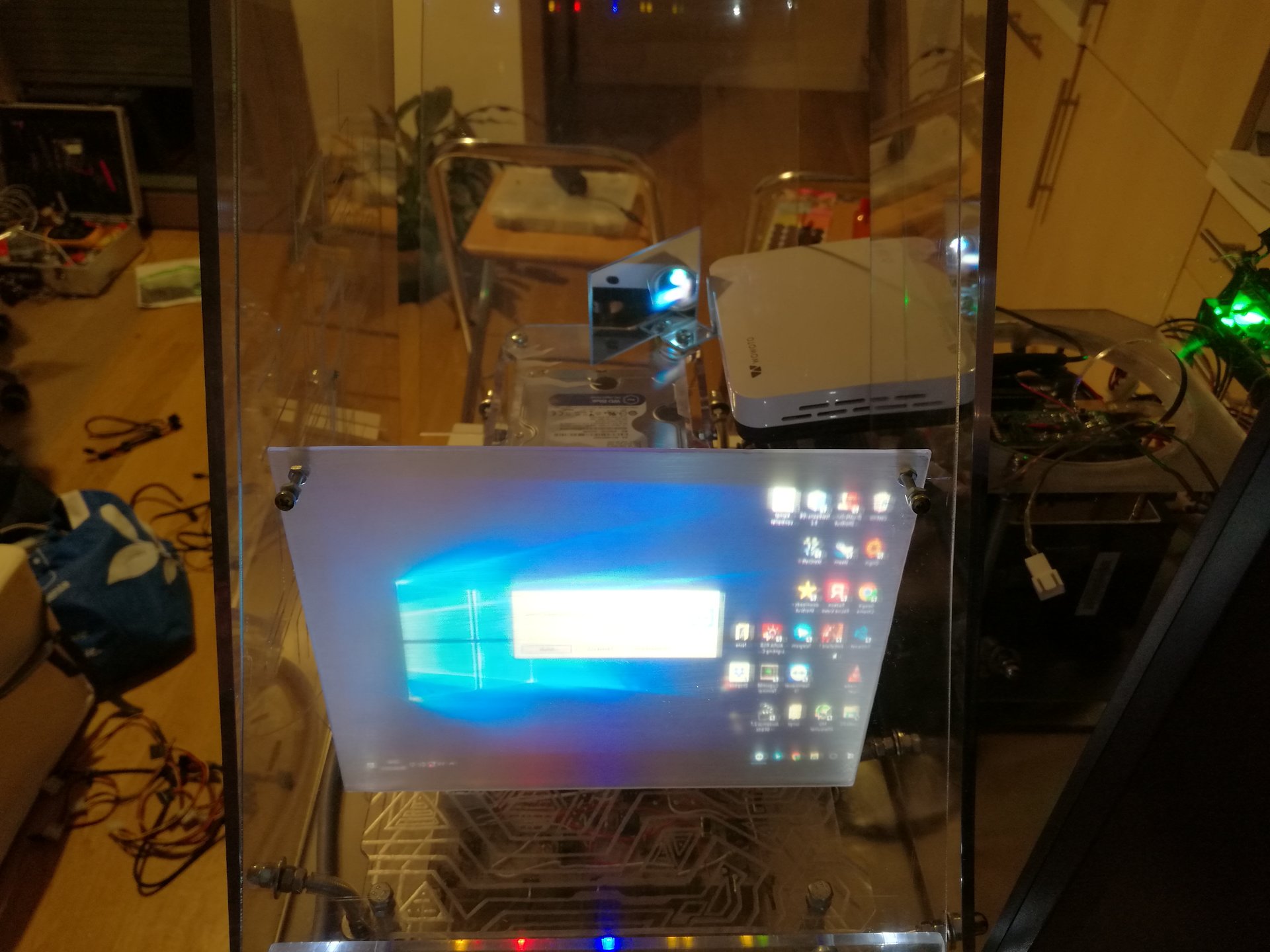
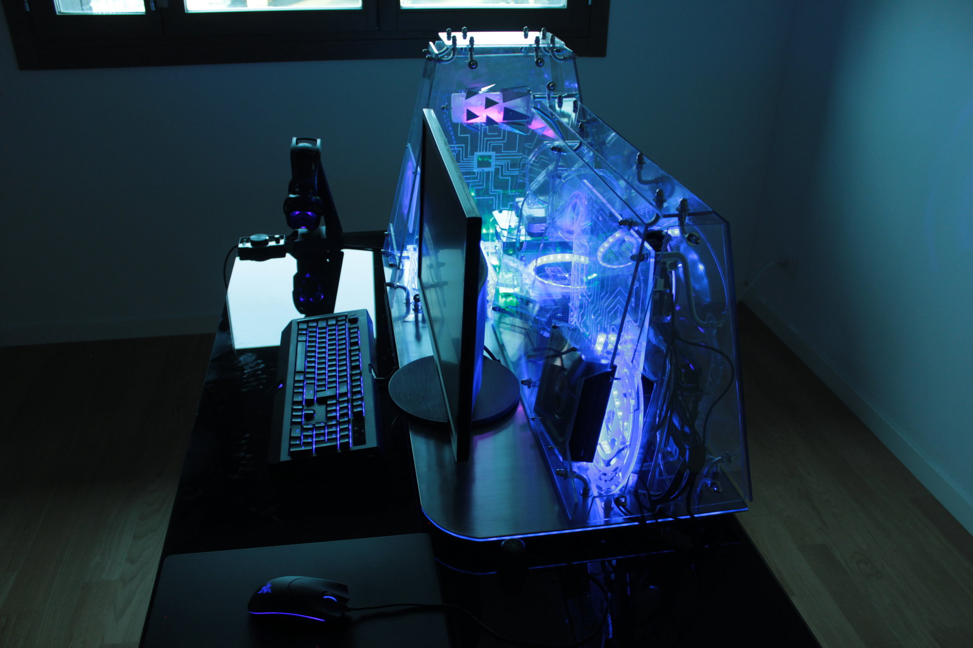
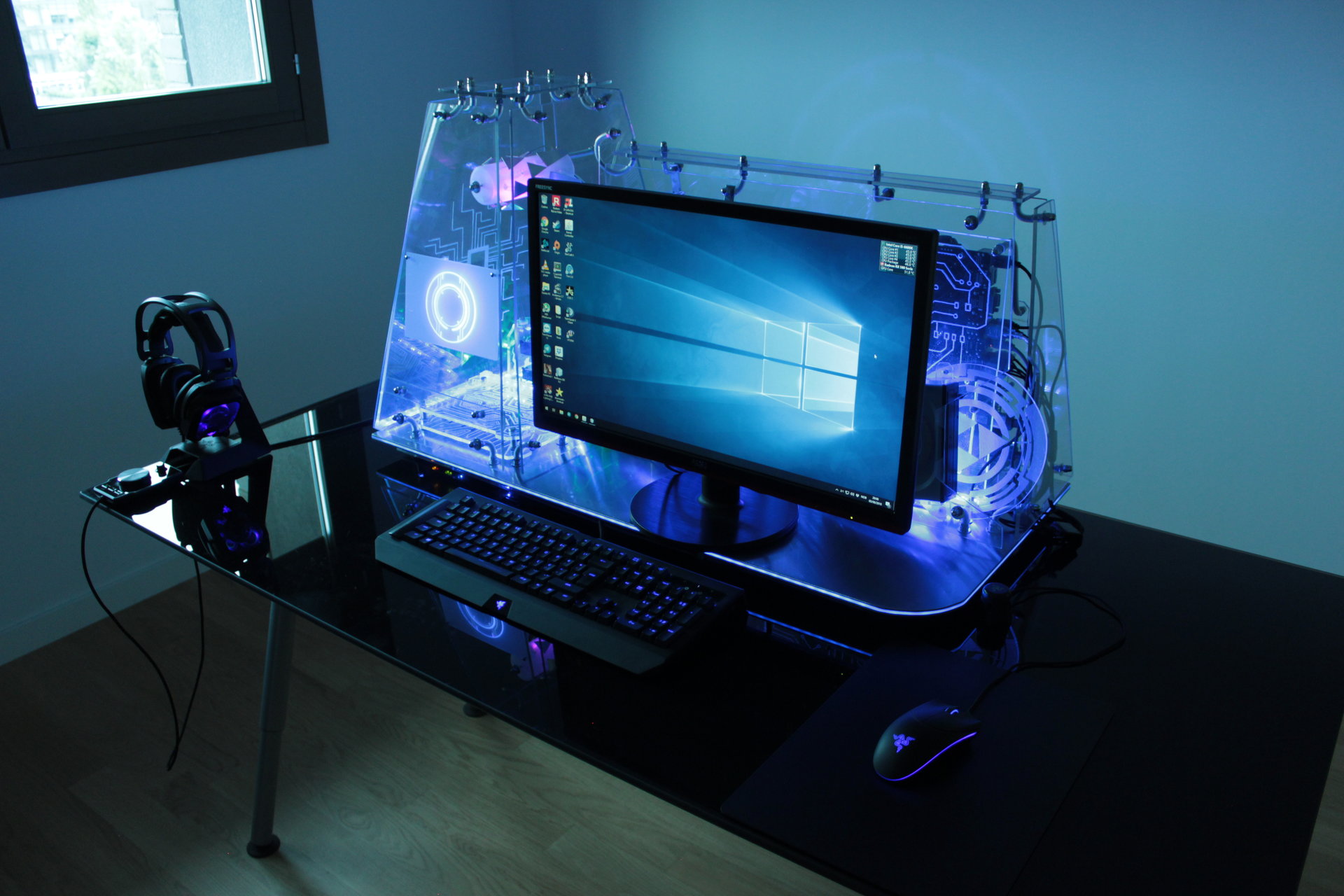
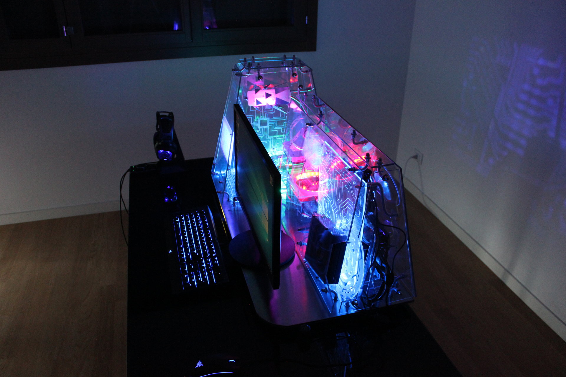
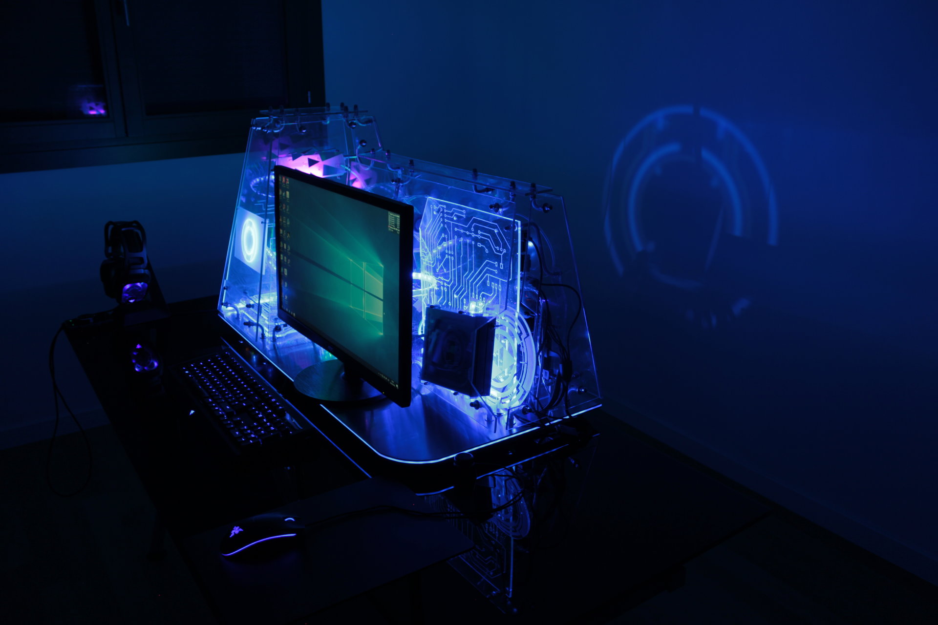
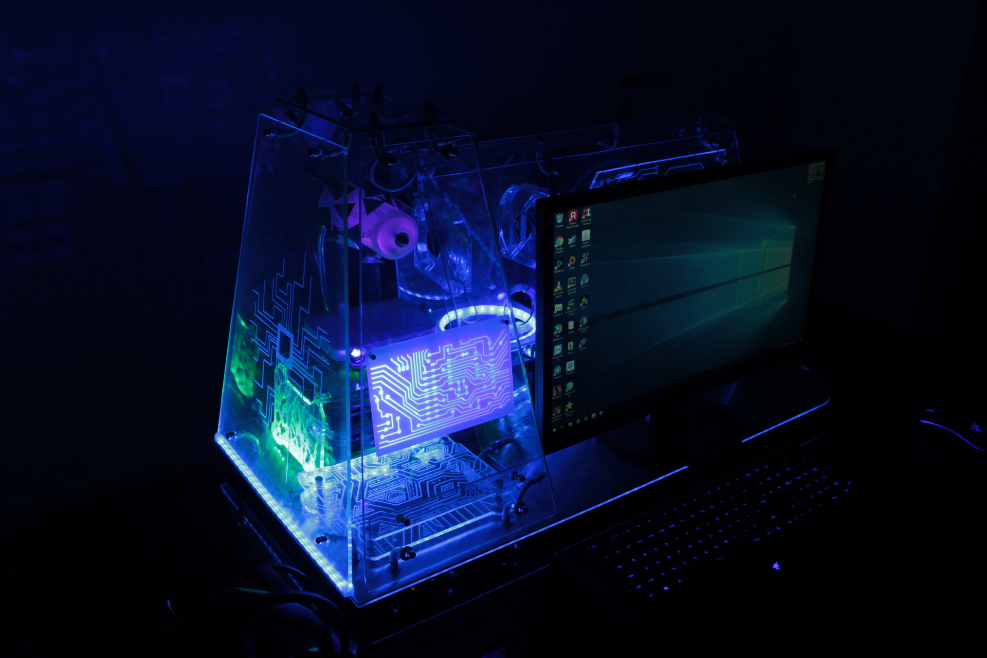
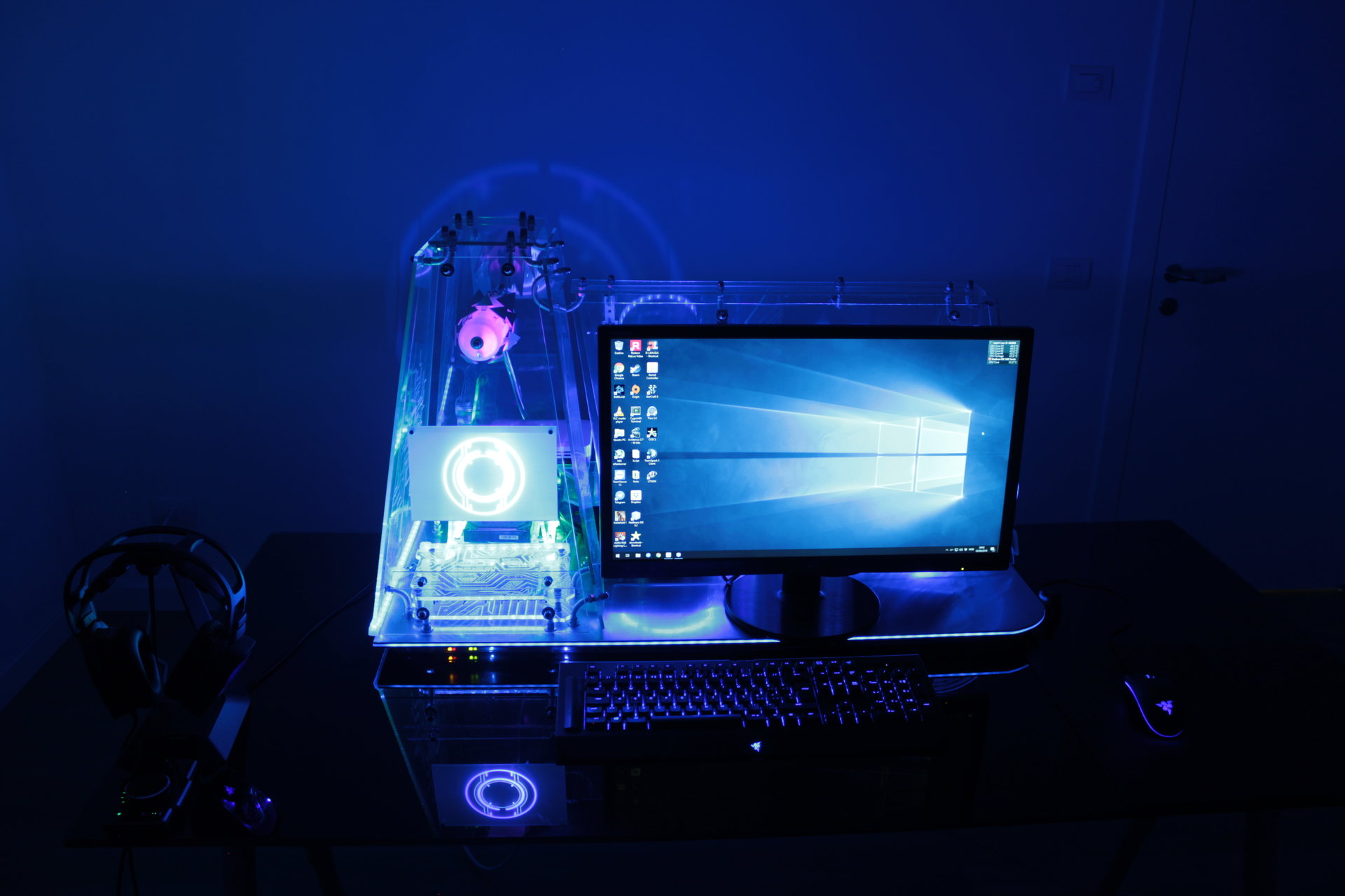
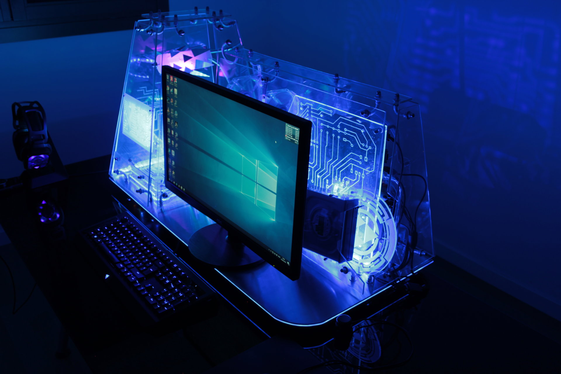
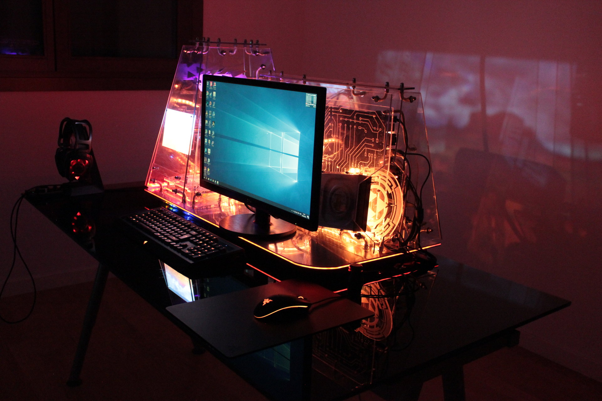
Powered on PC, but with light in the room:
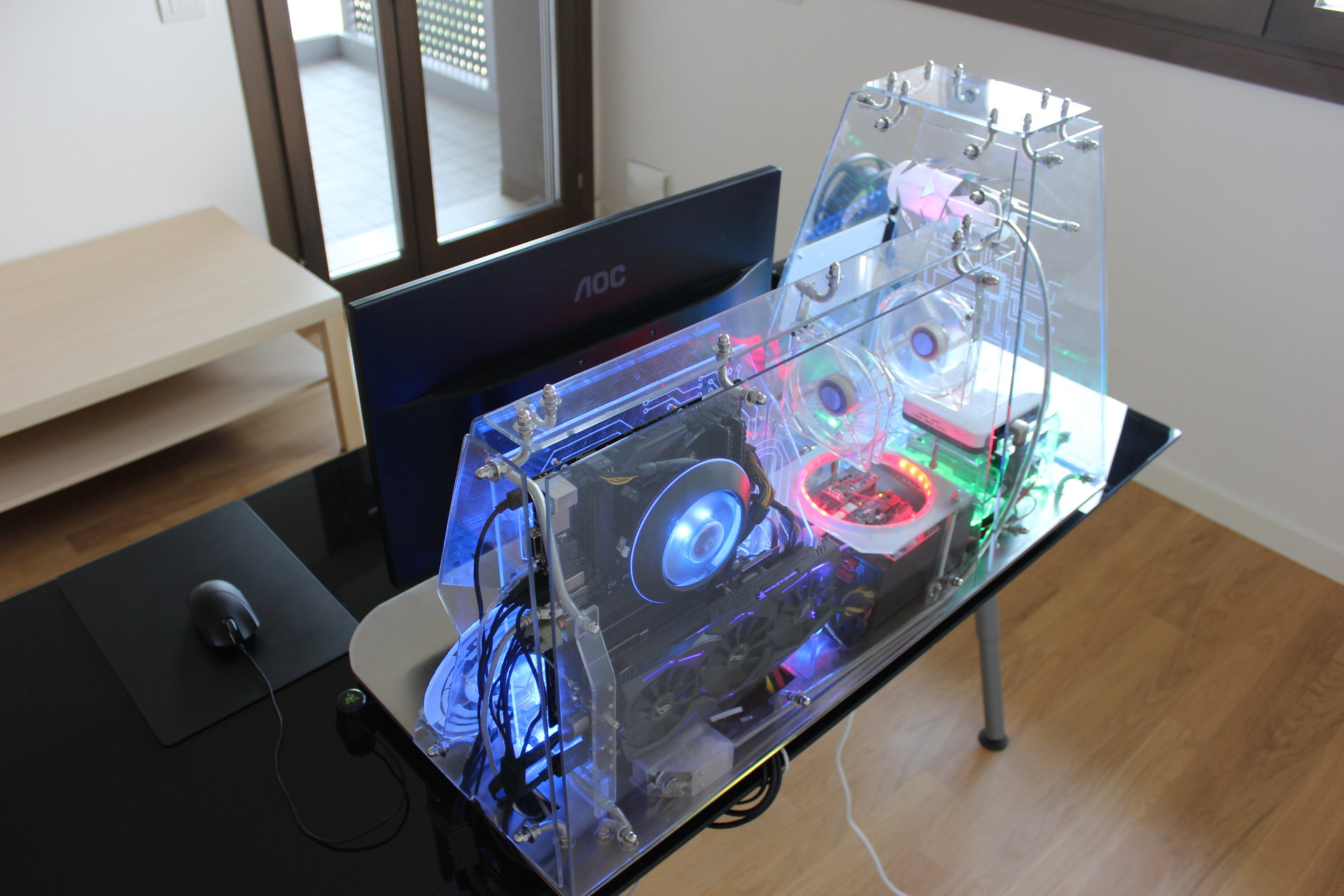
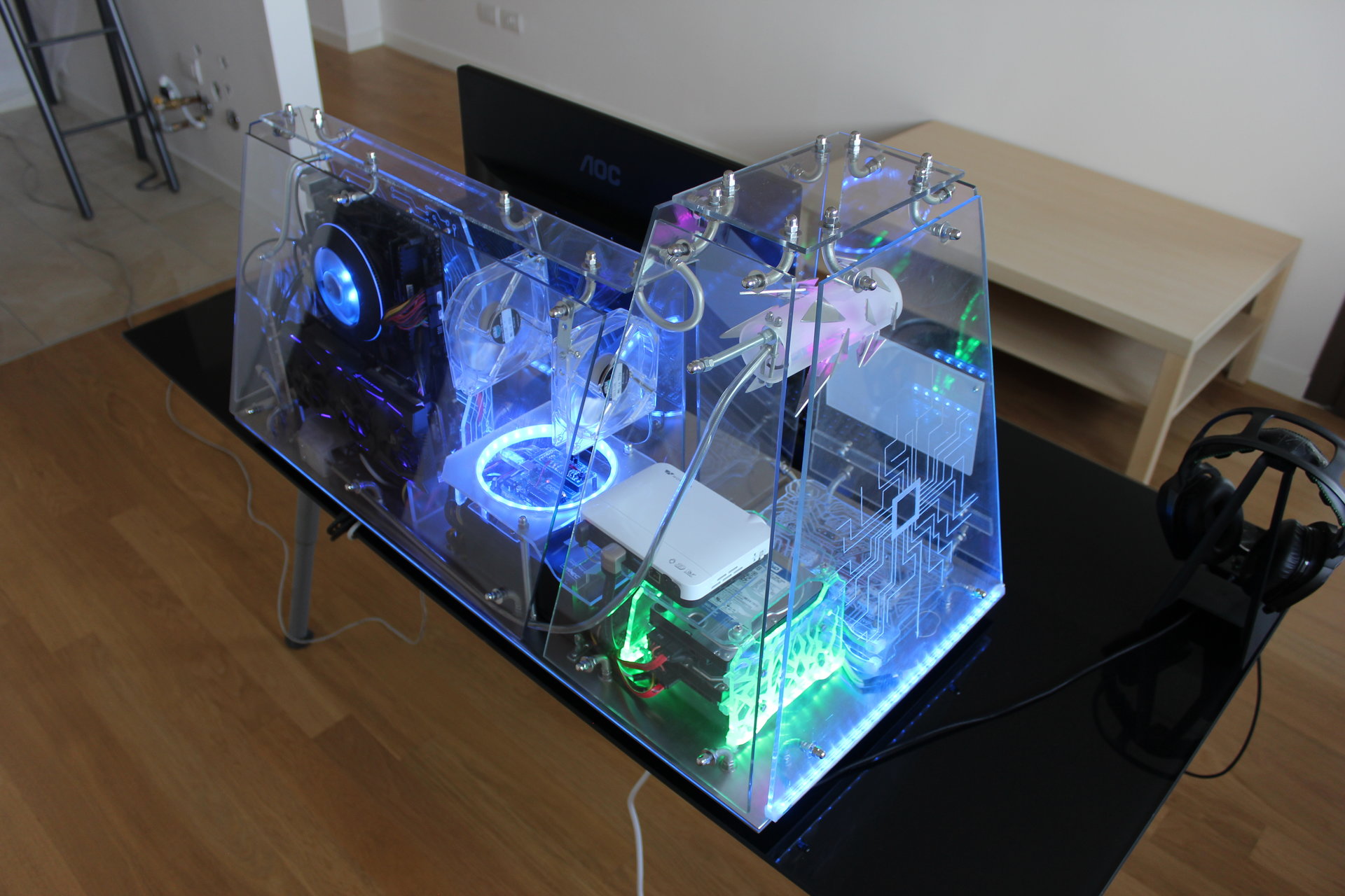
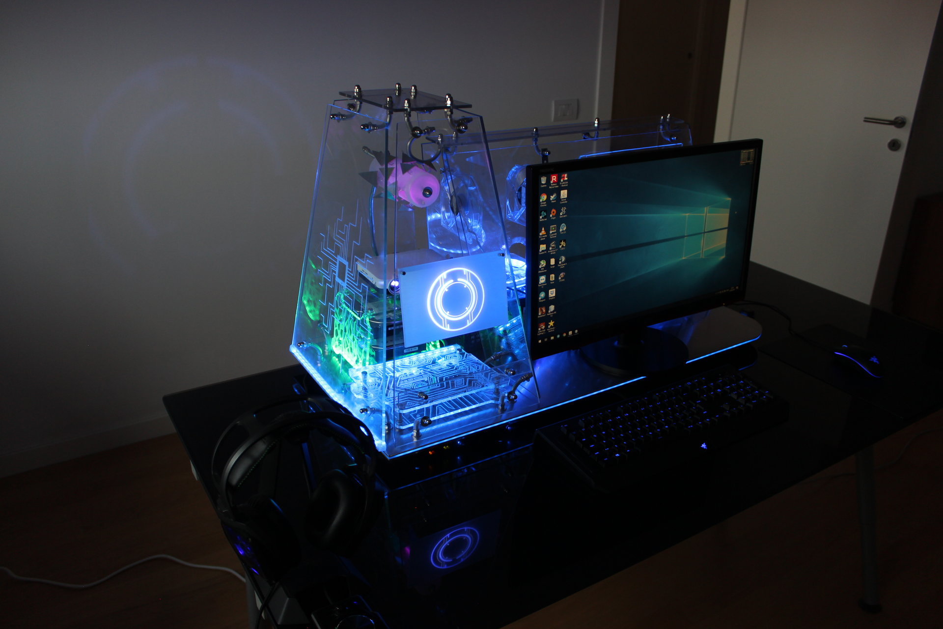
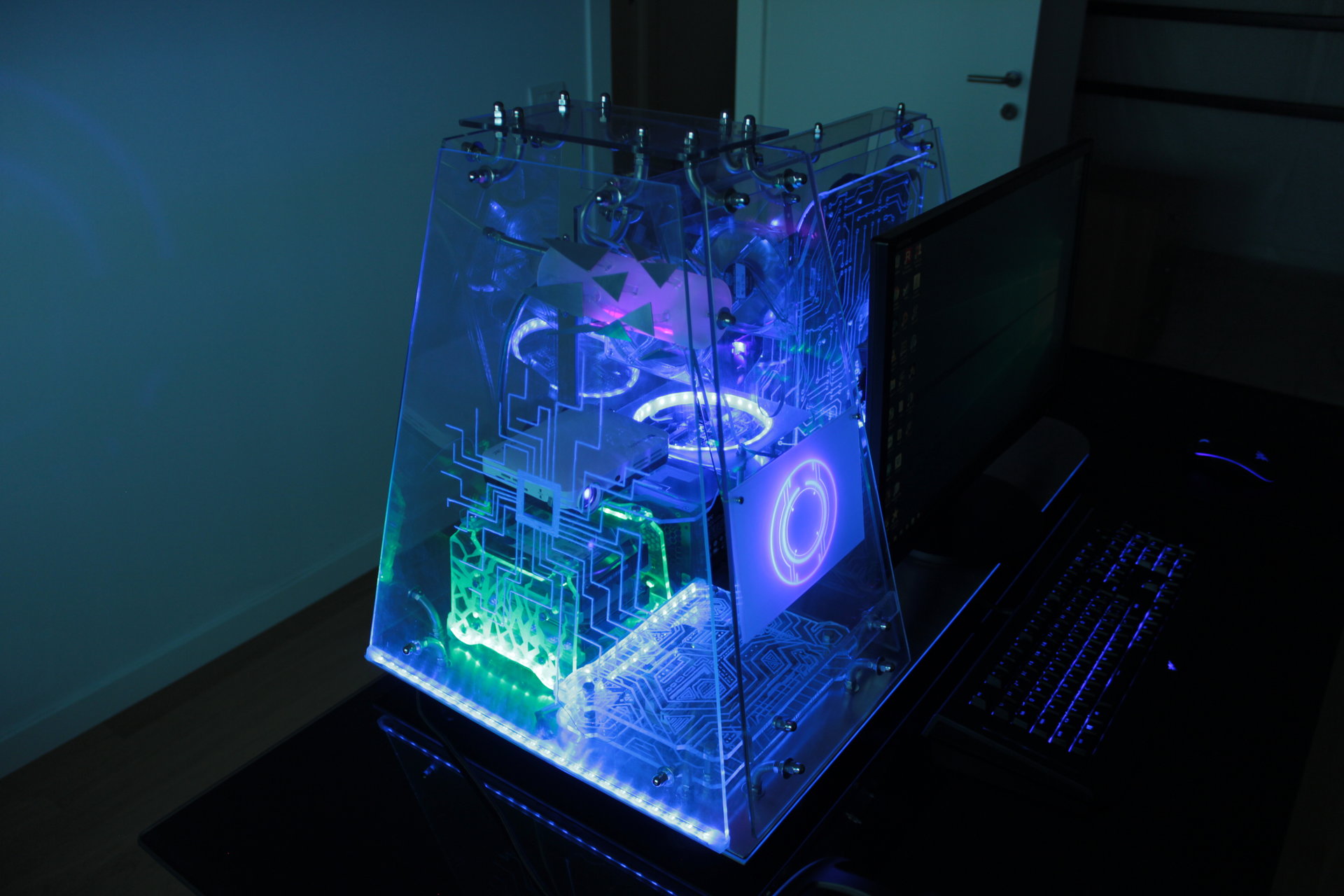
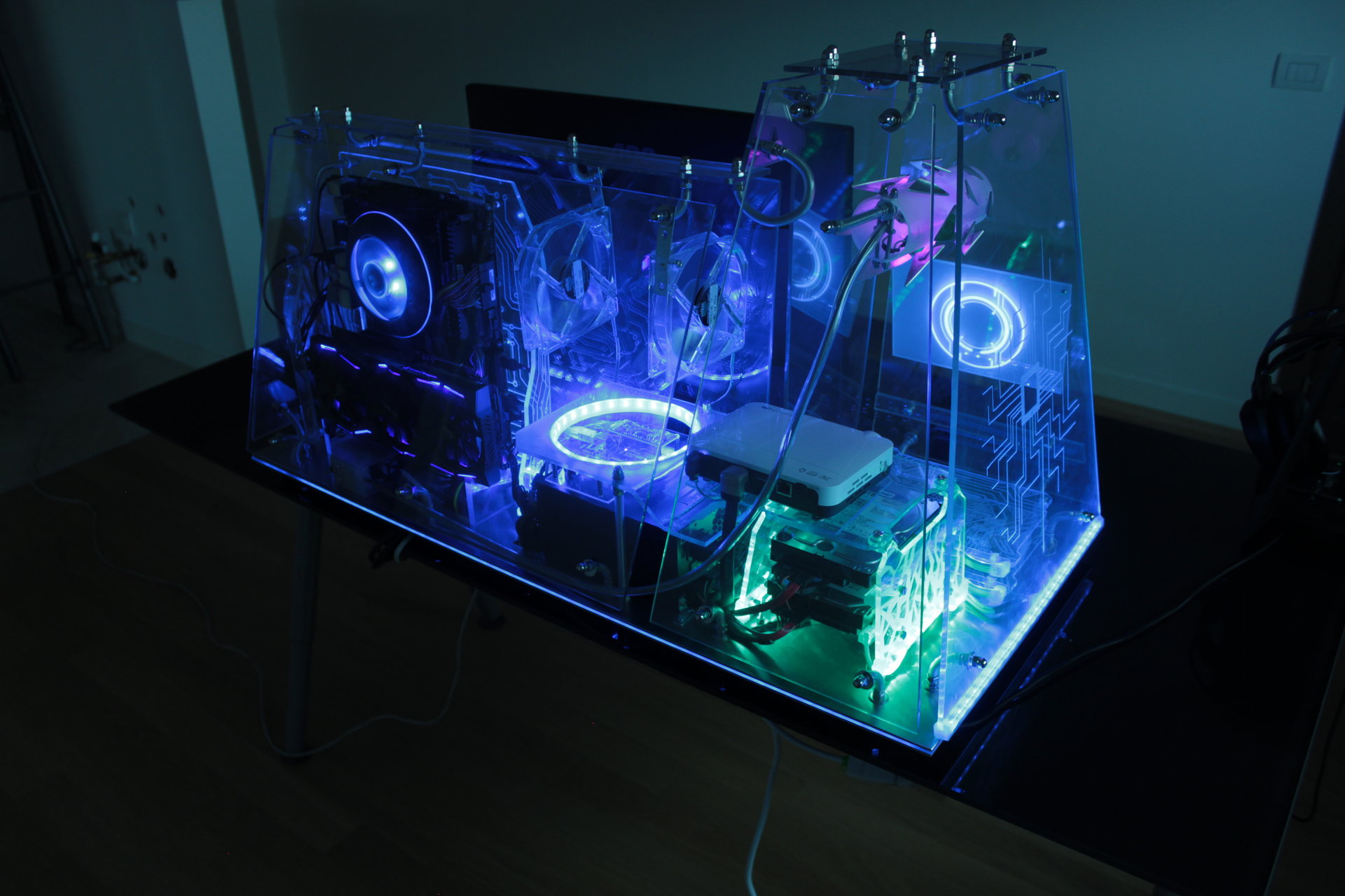
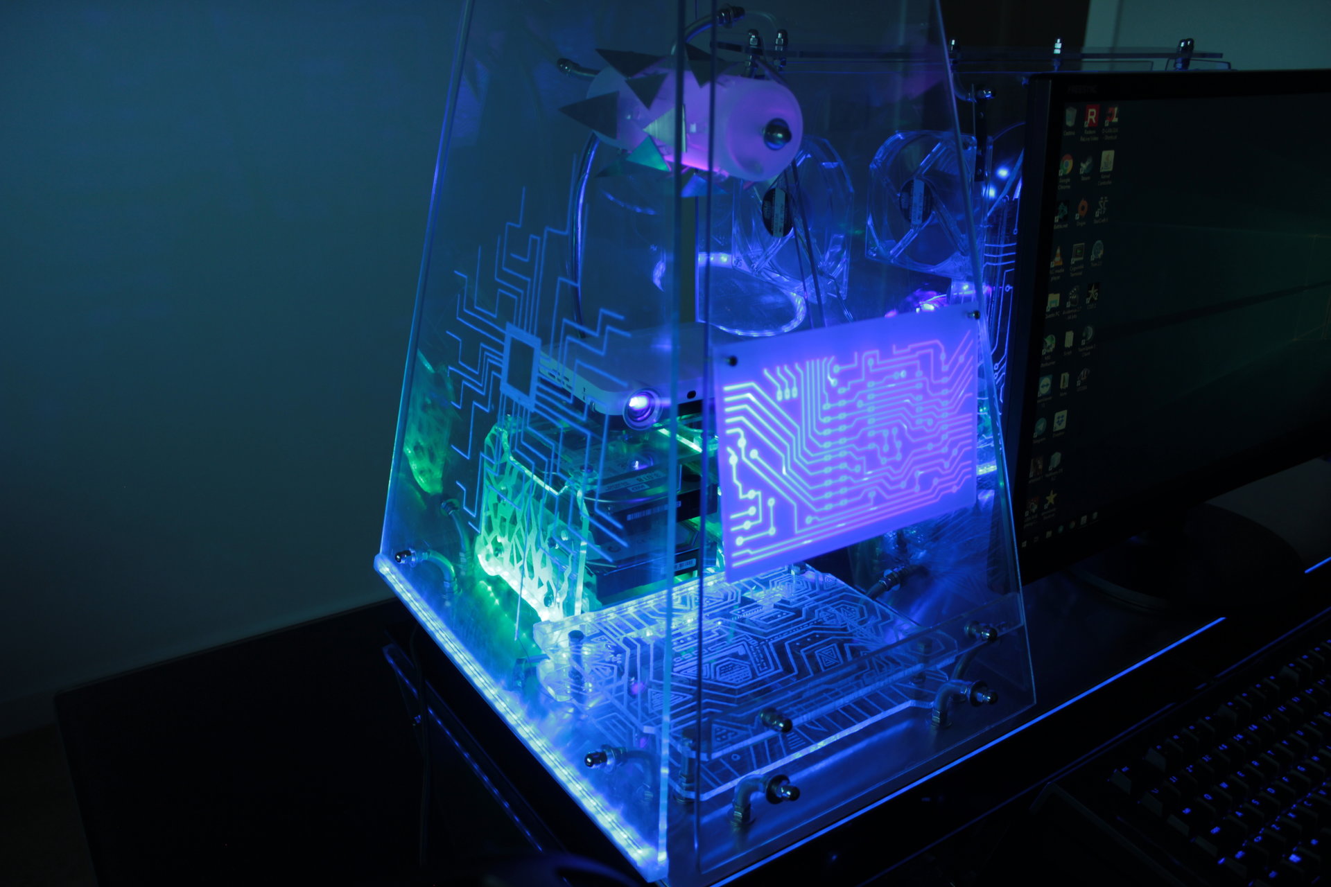
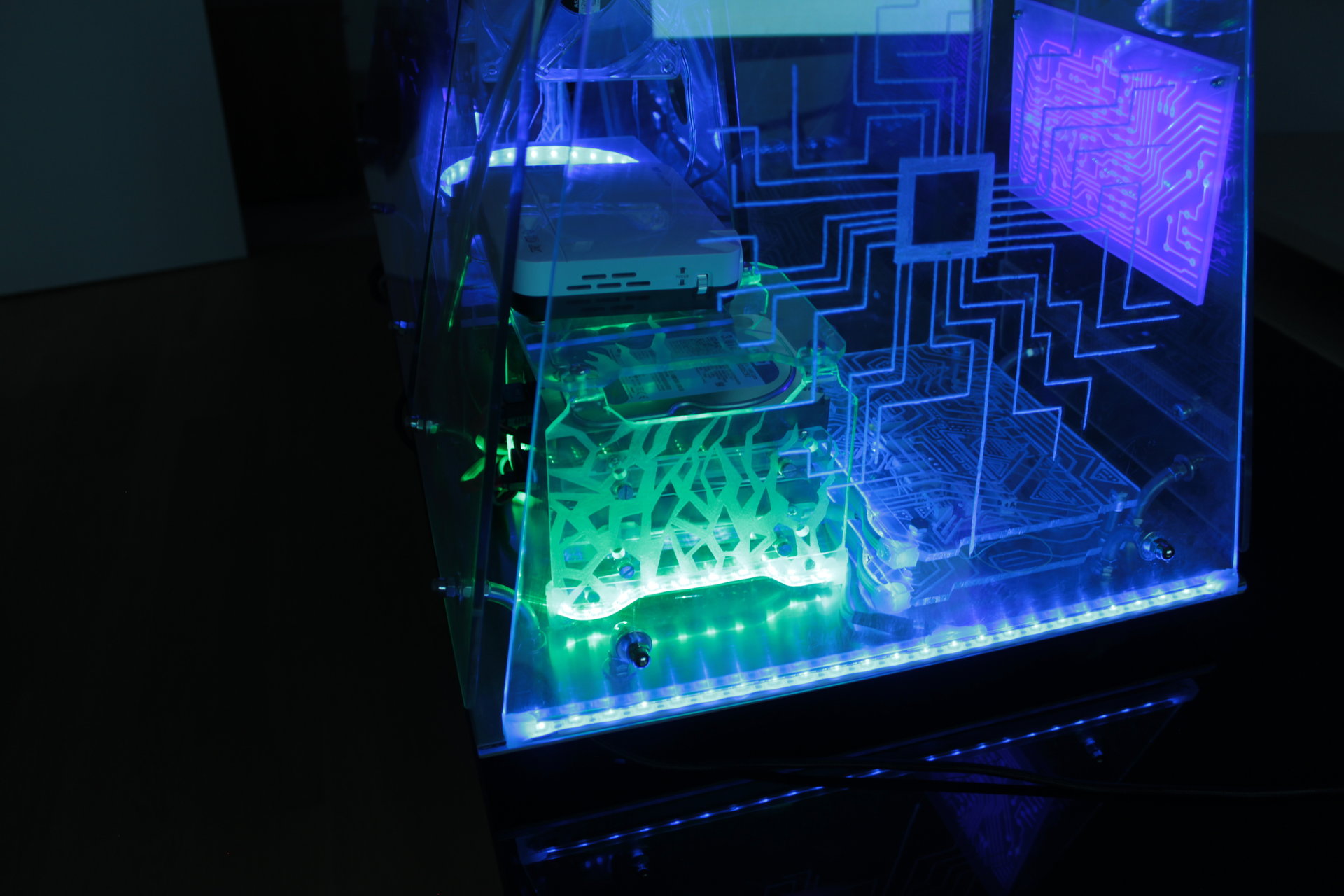
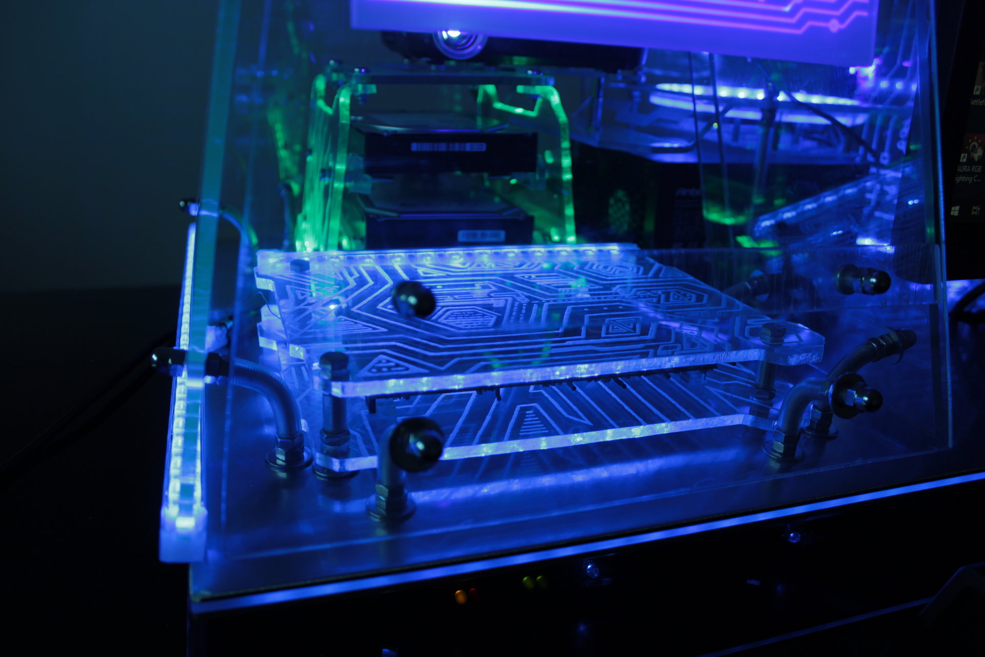

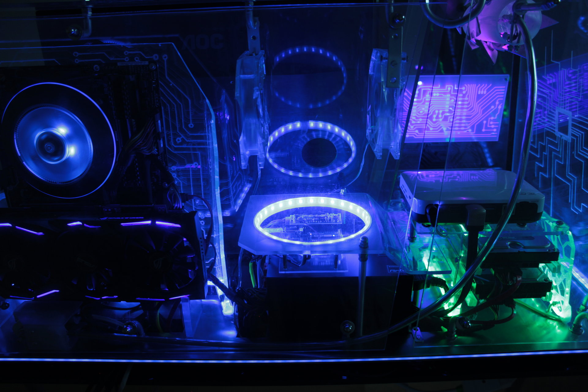
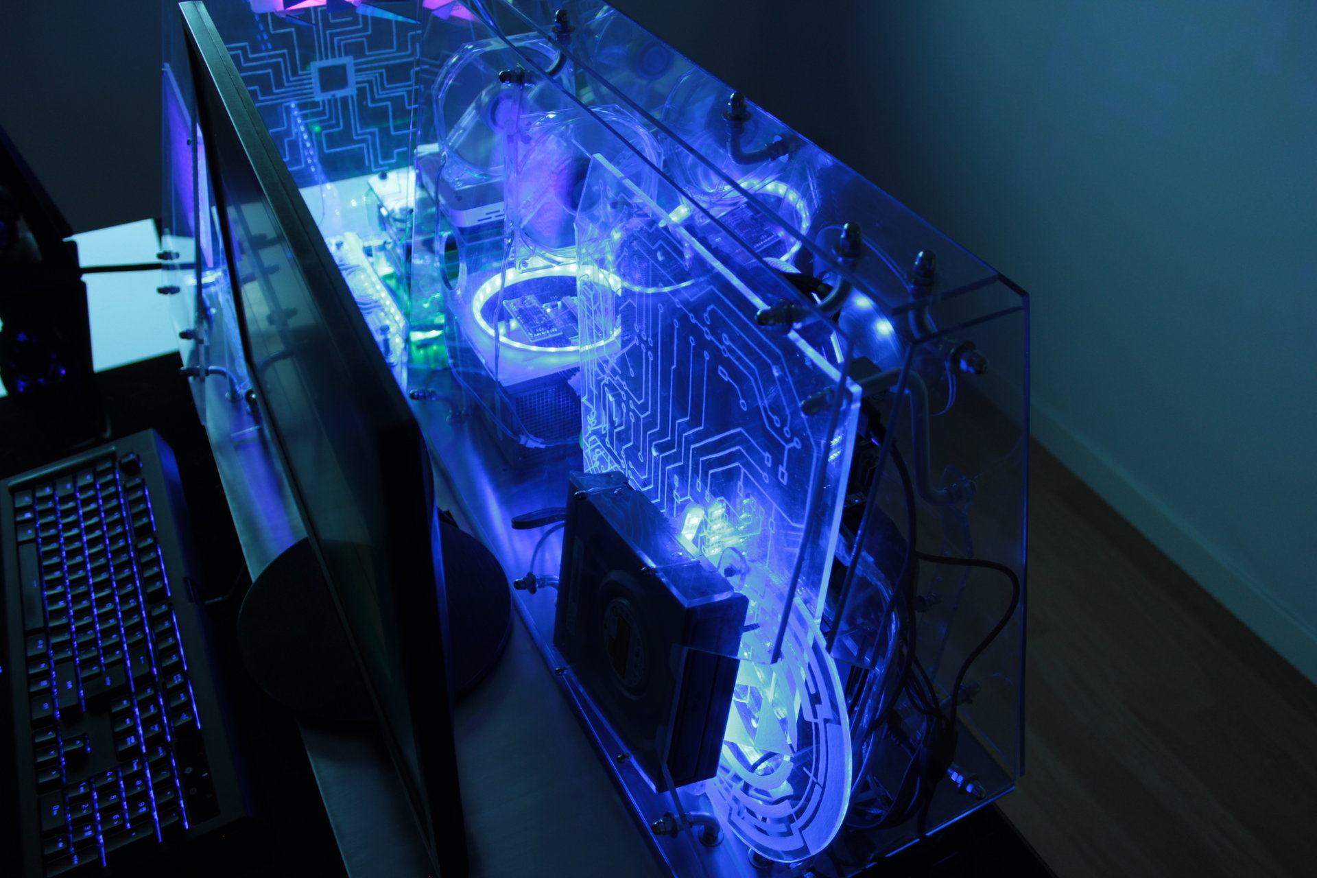
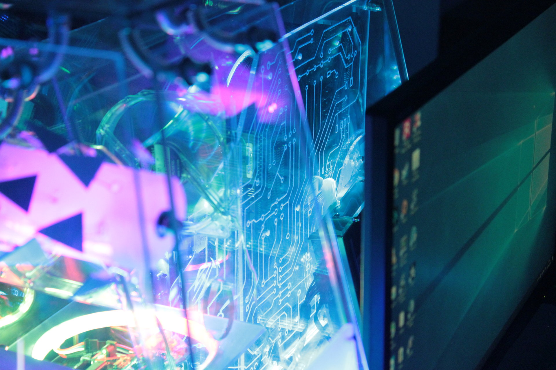
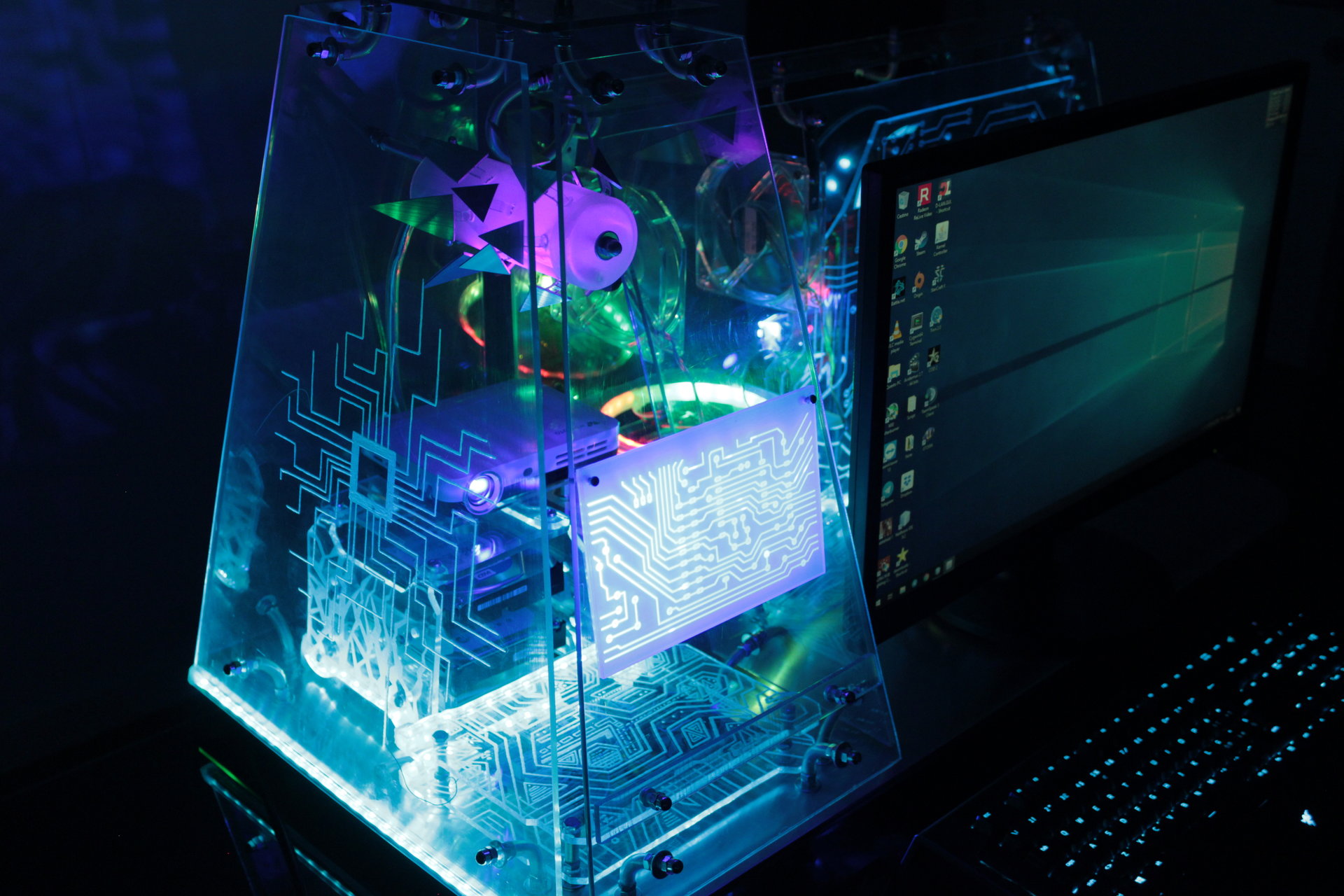
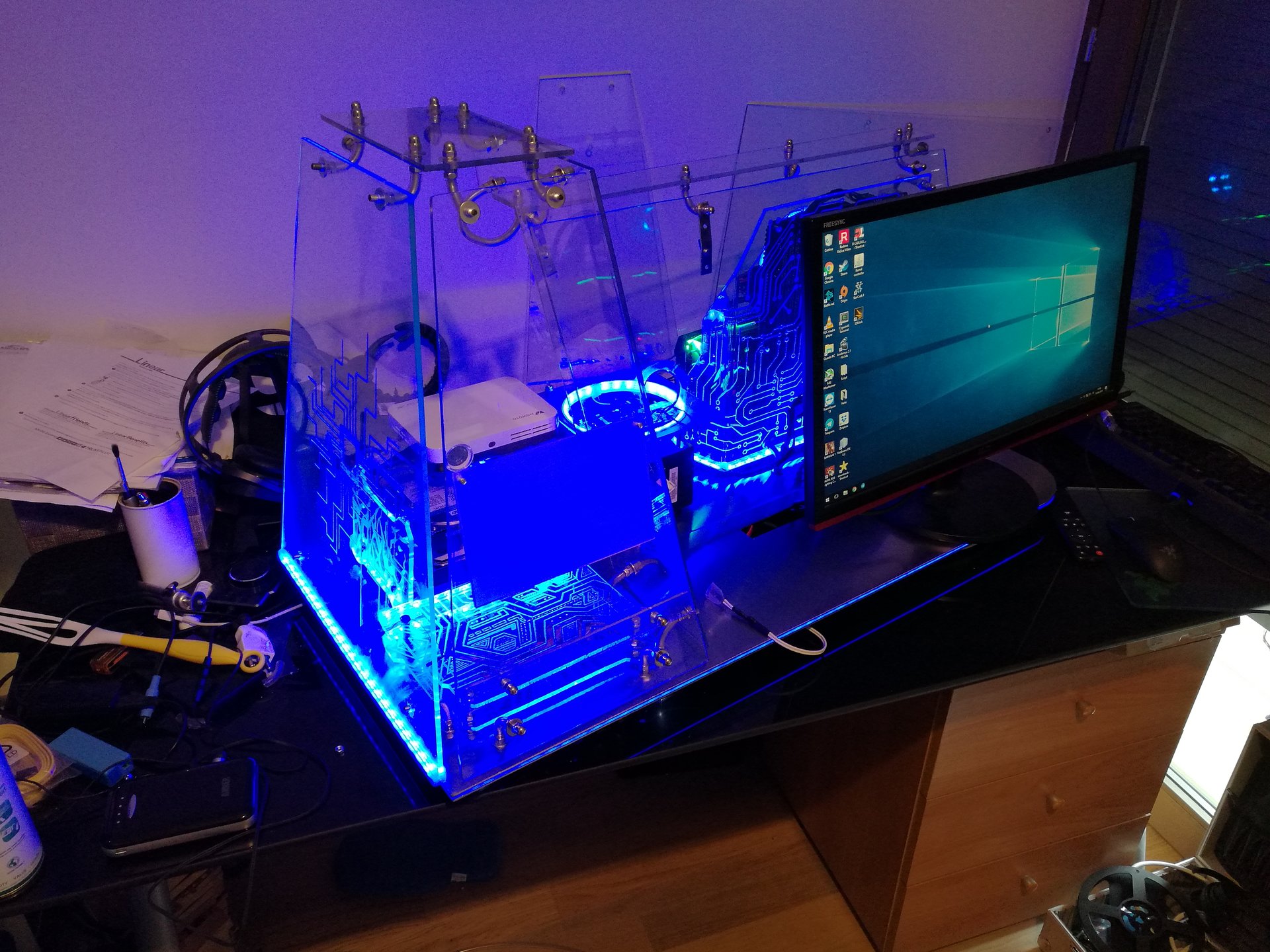
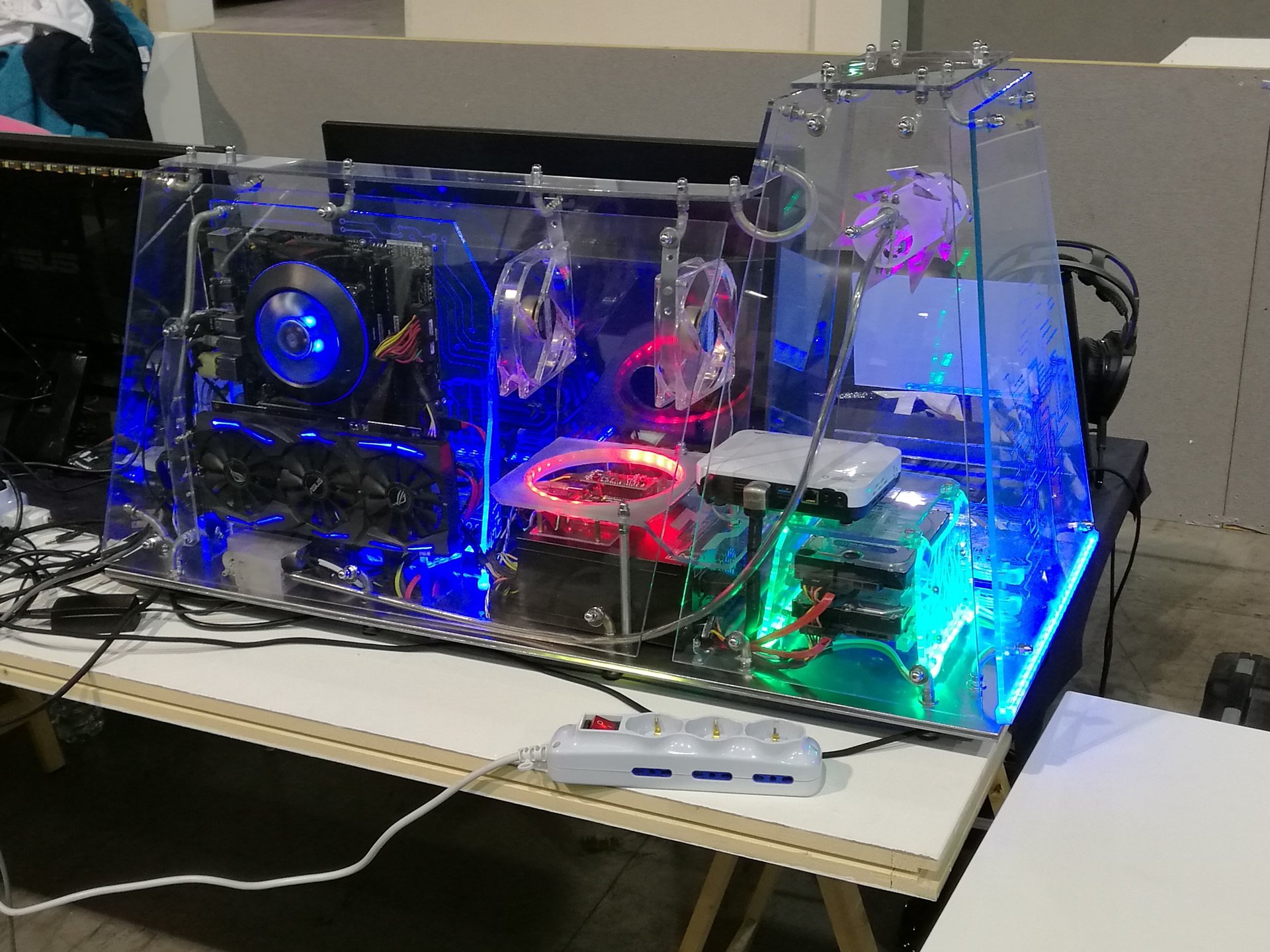
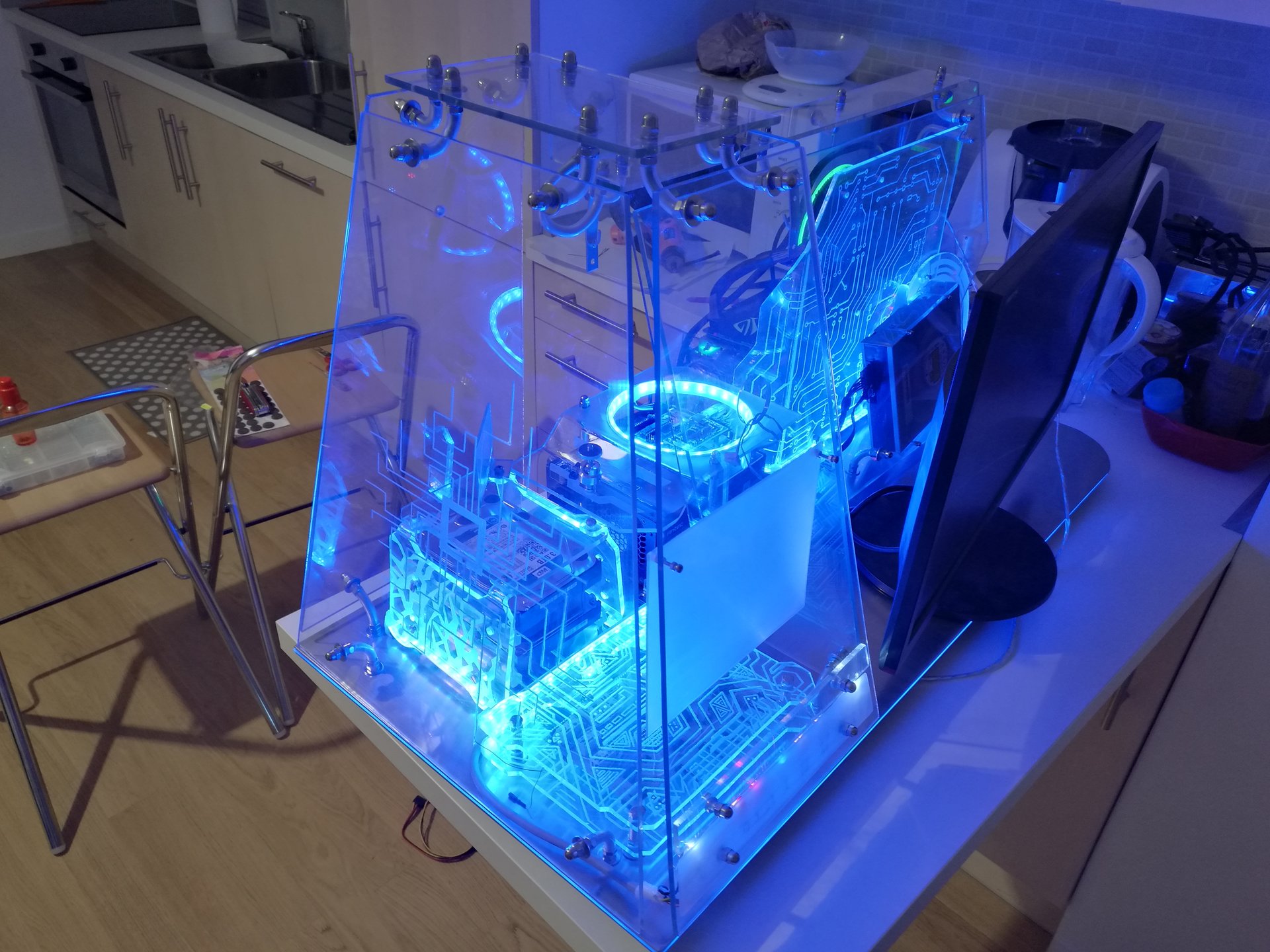
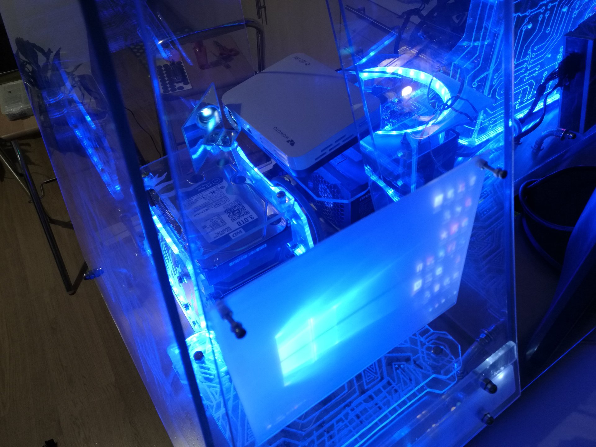
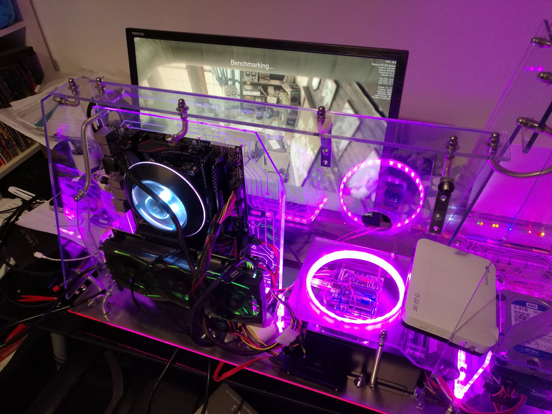
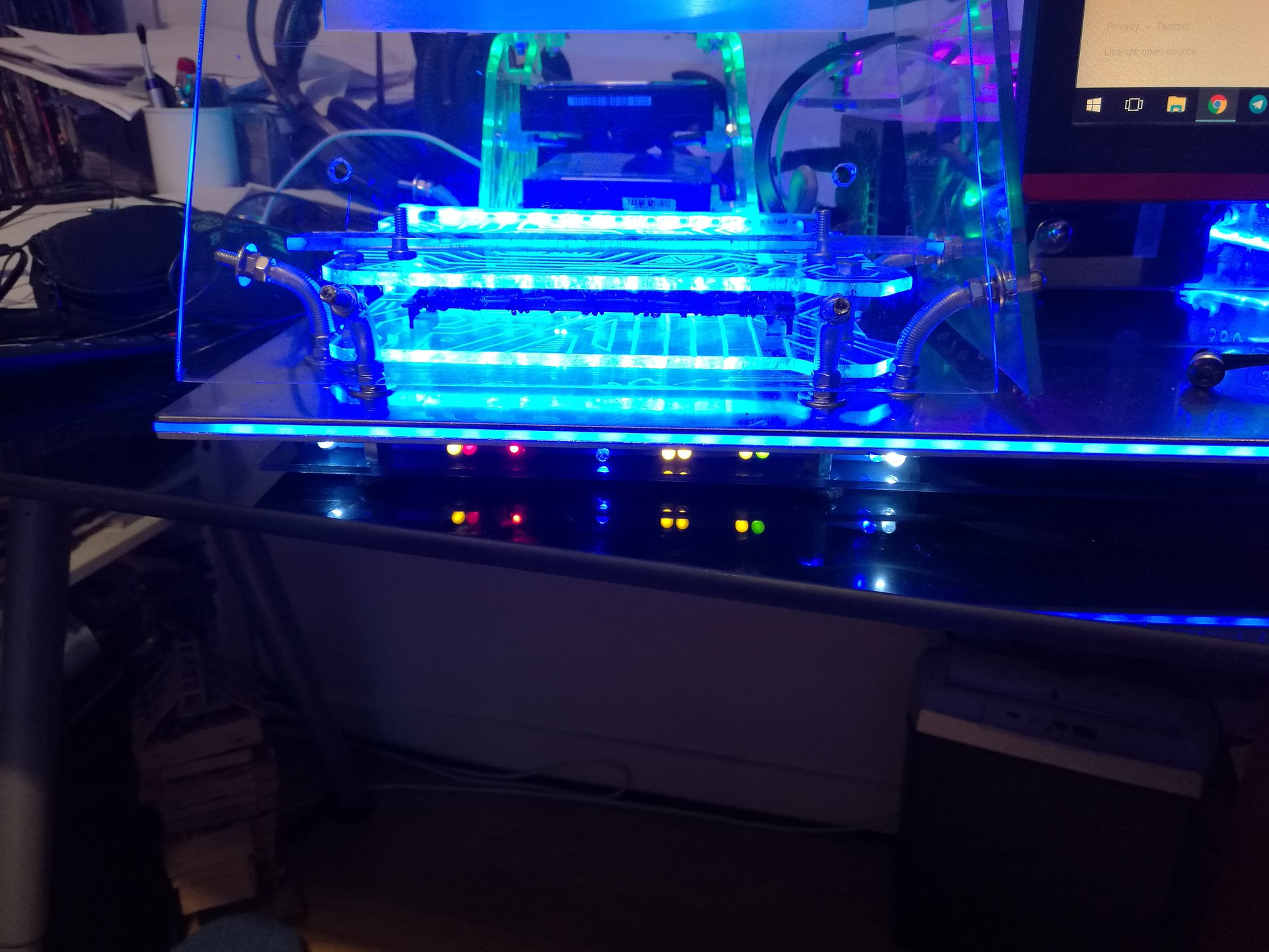
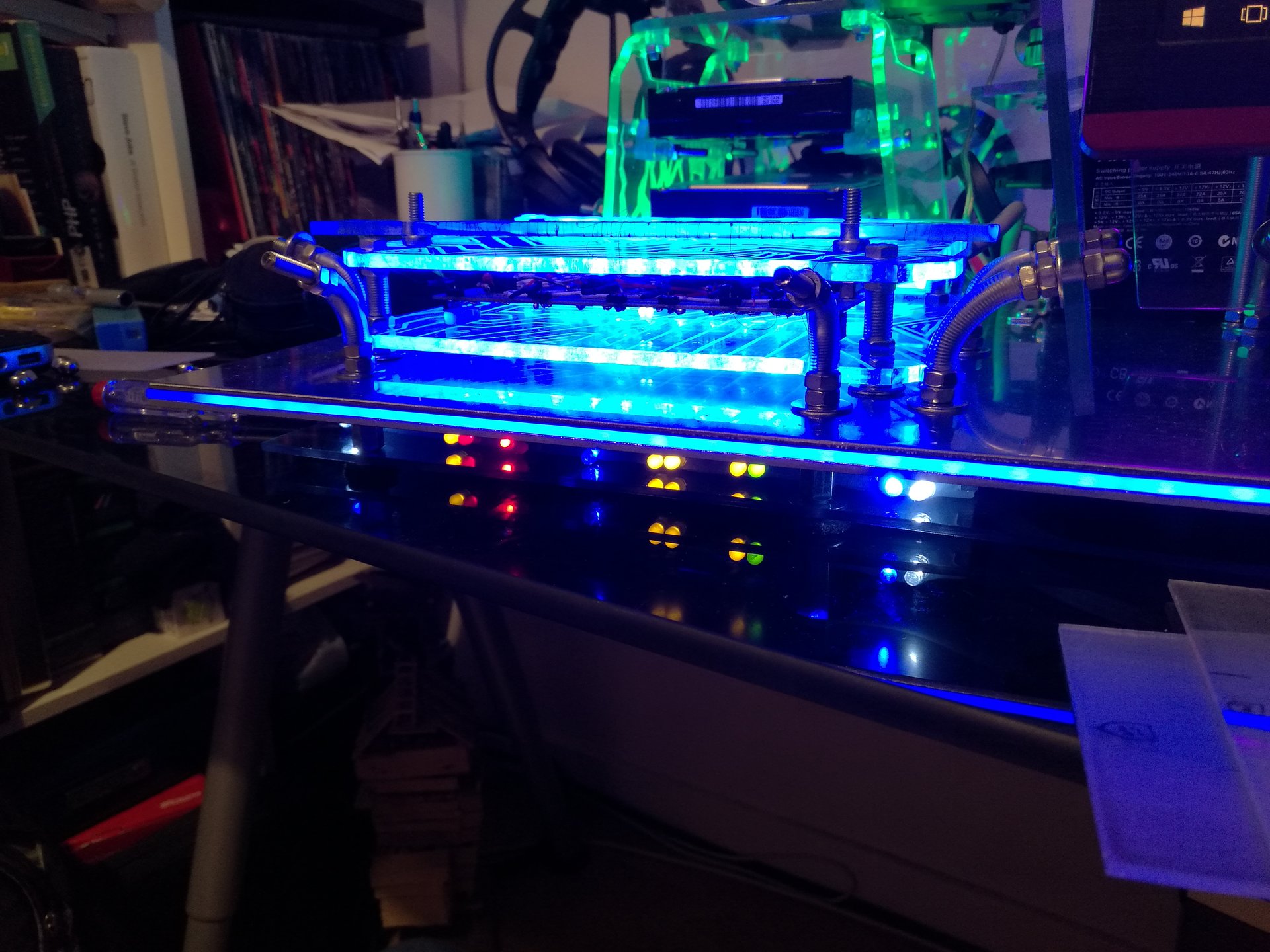
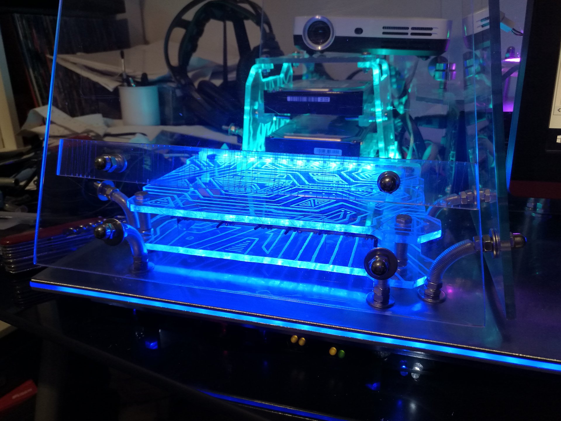
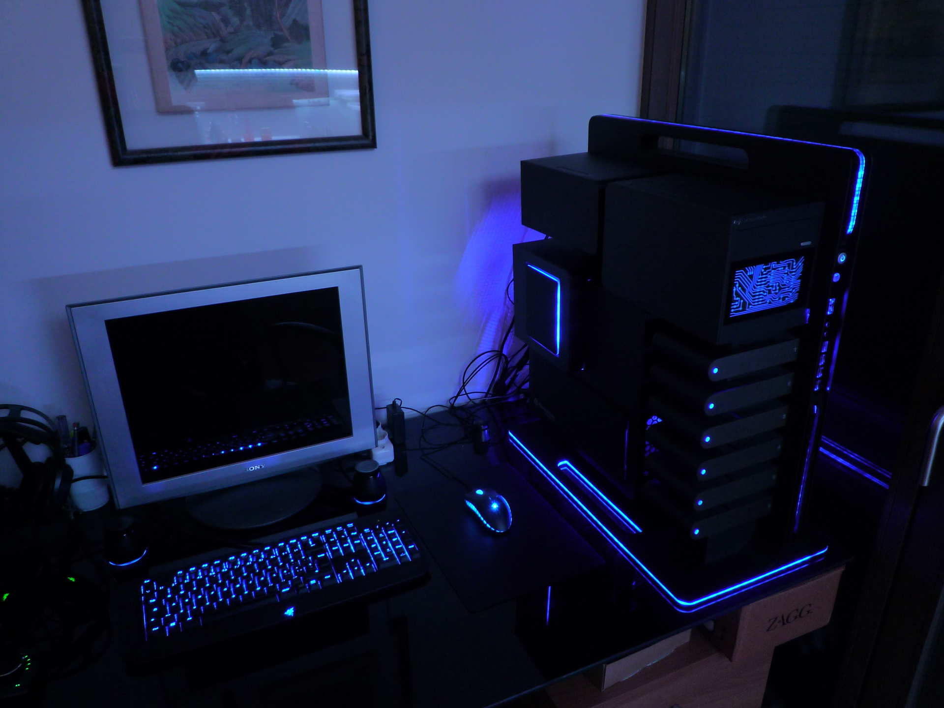
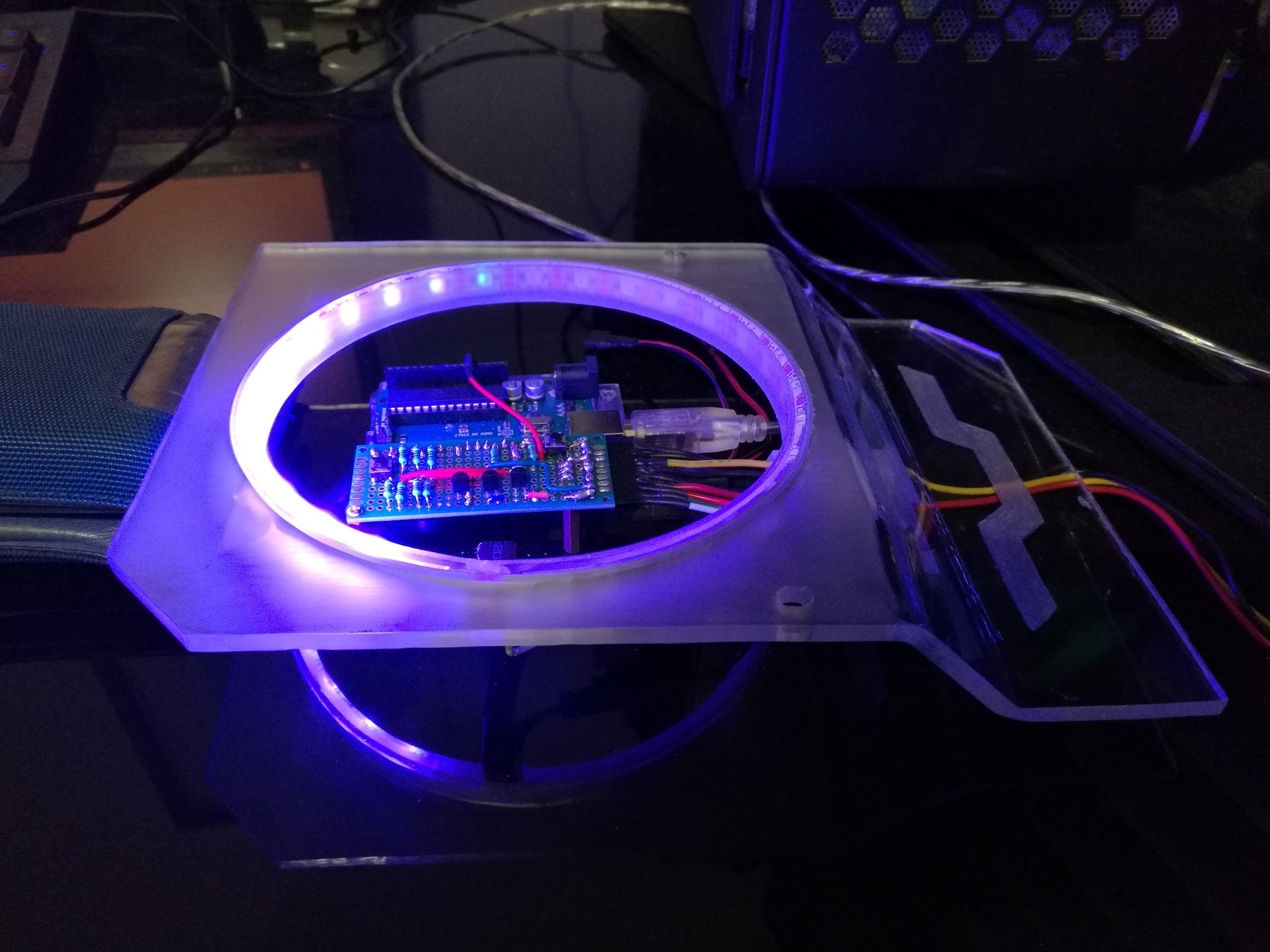
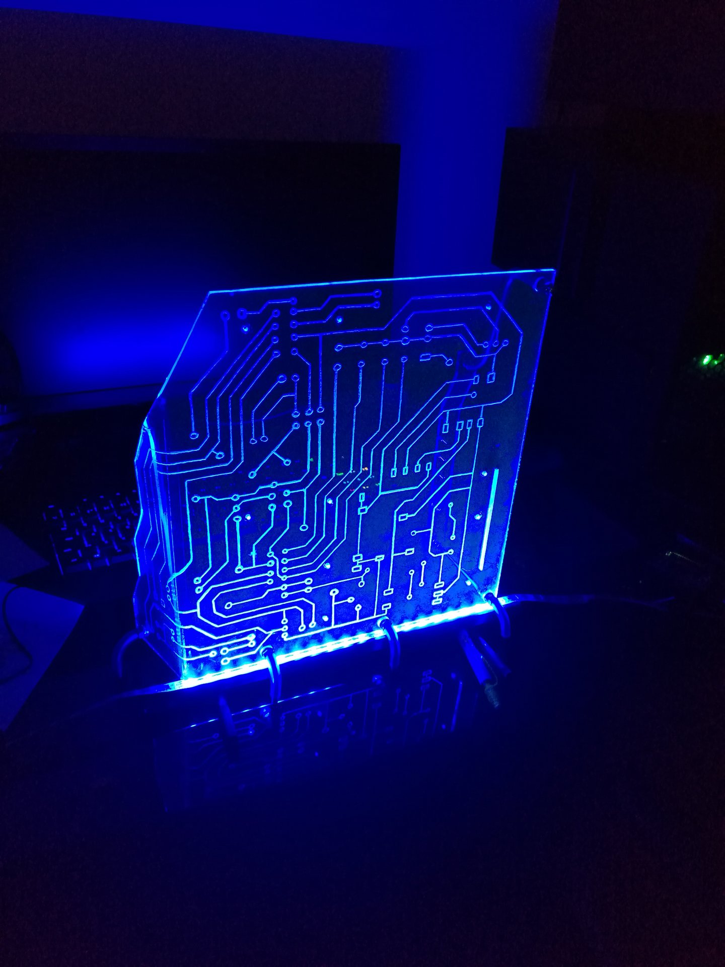
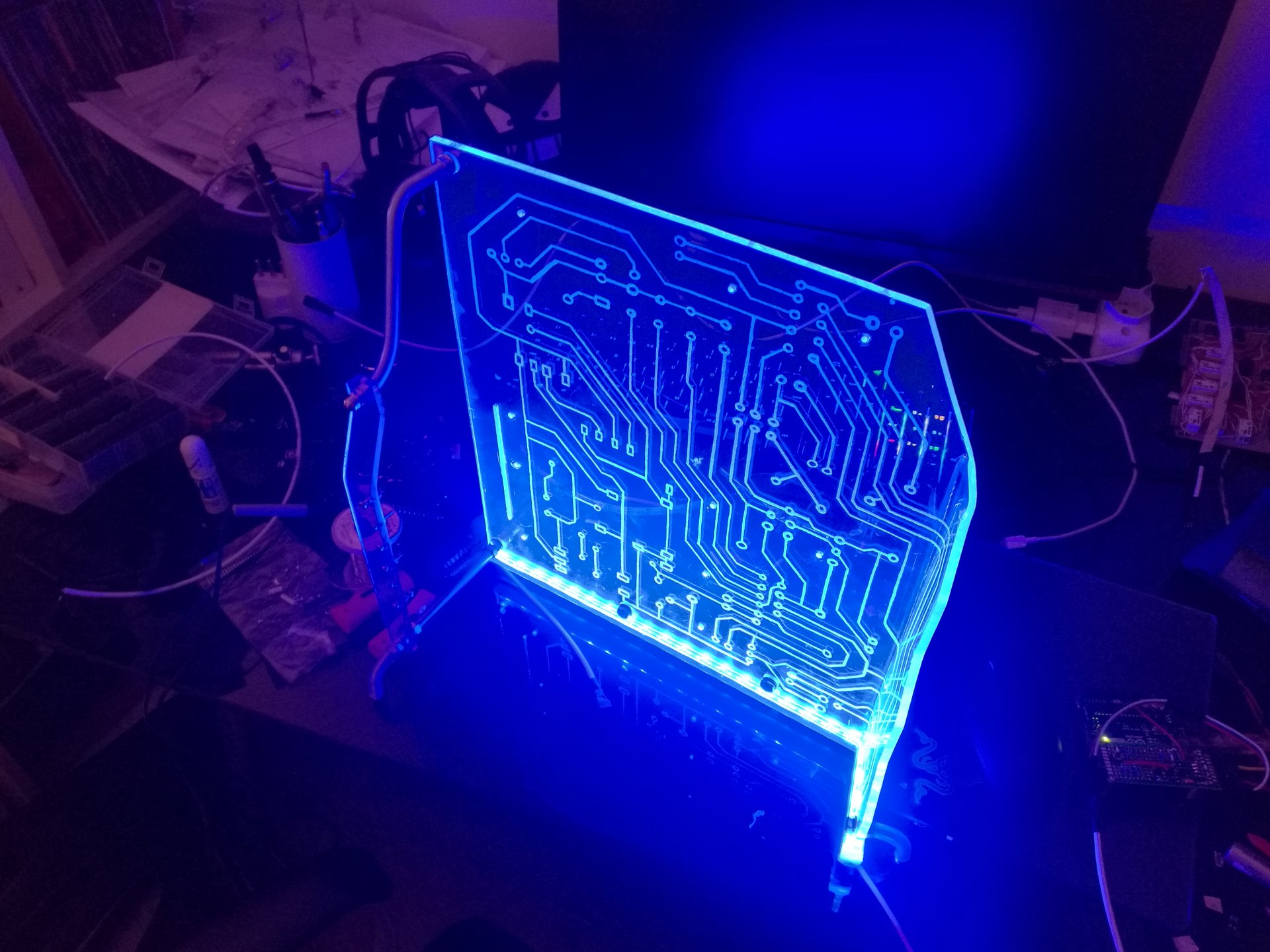
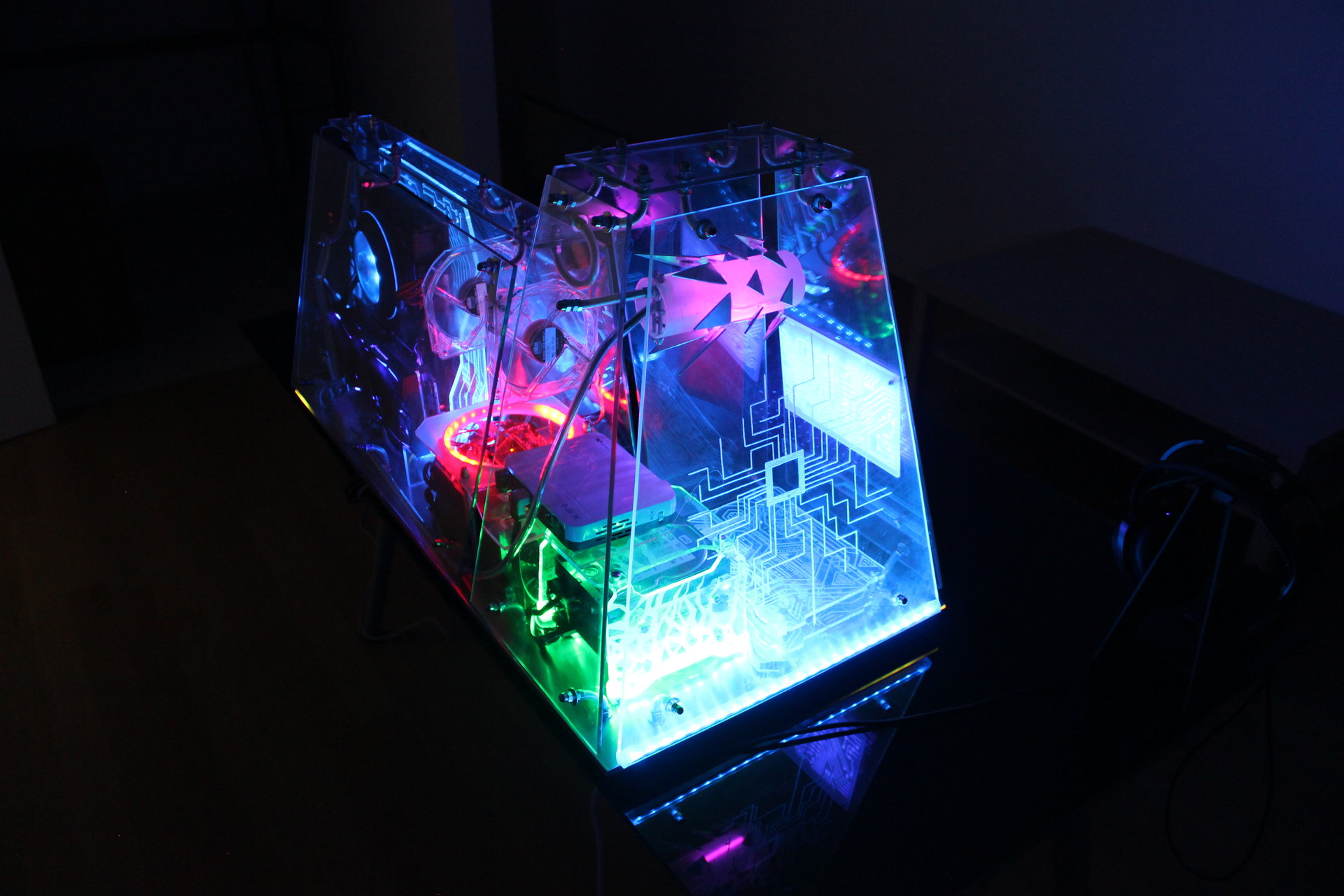
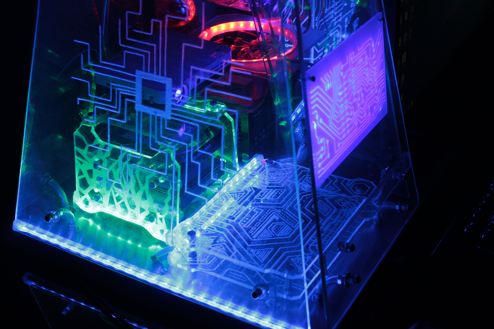
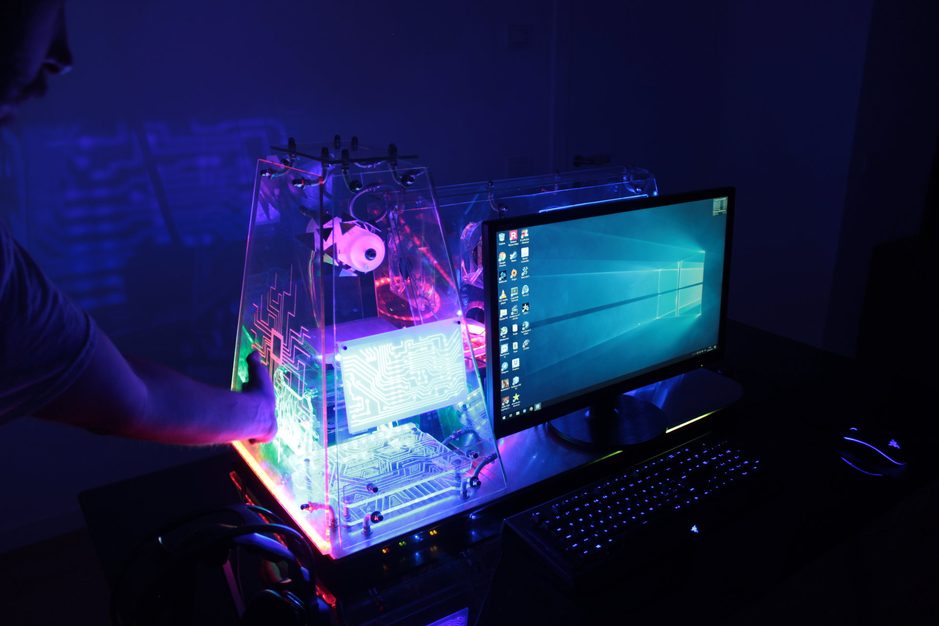
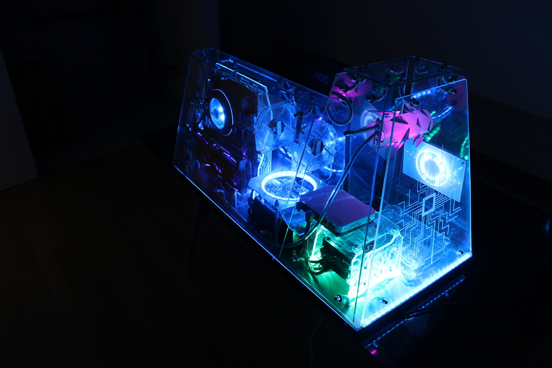
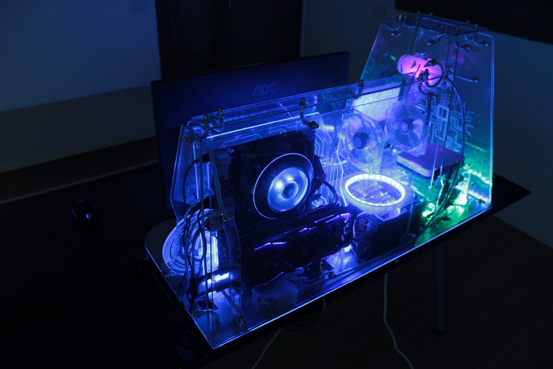
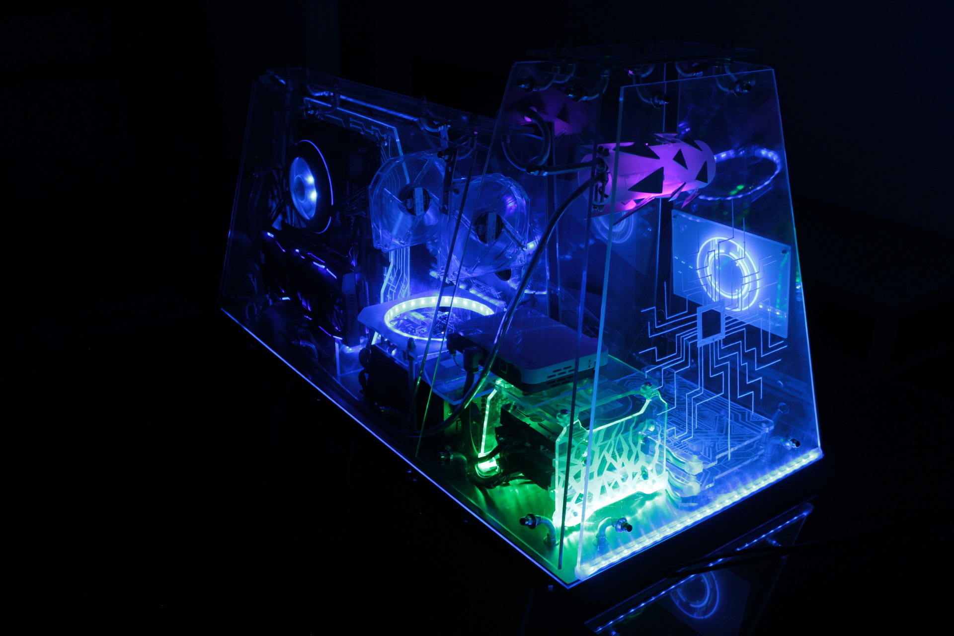
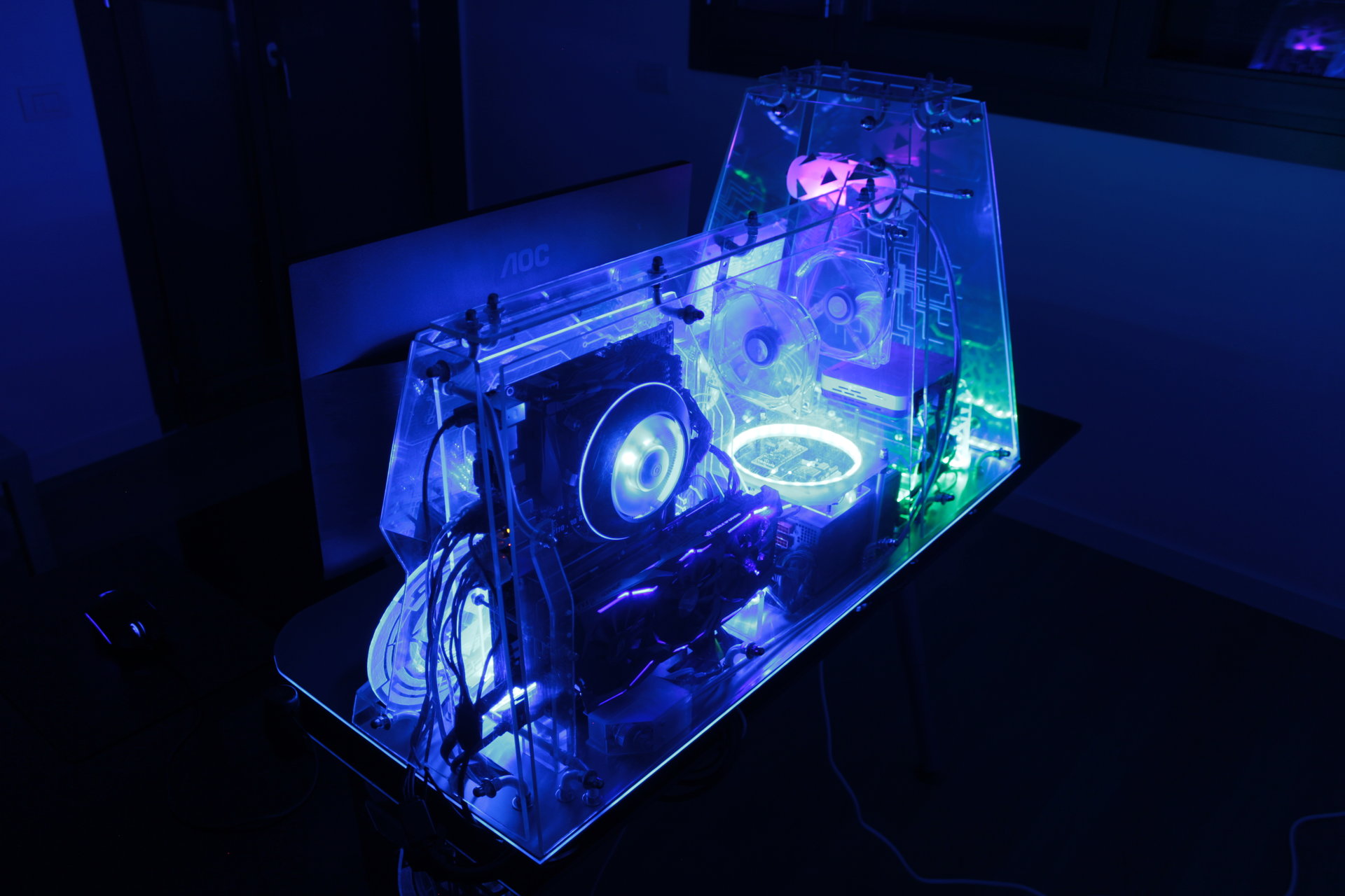
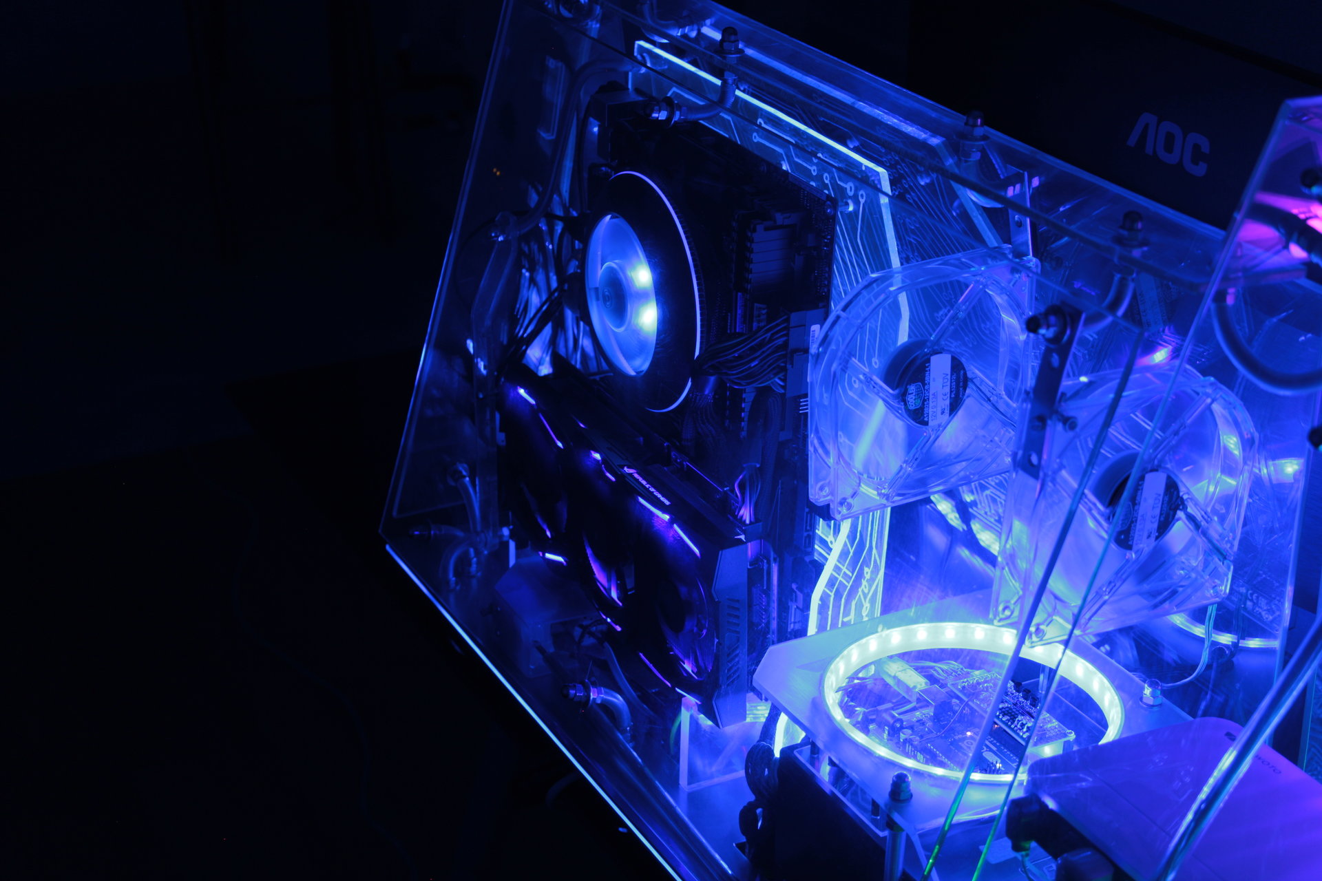
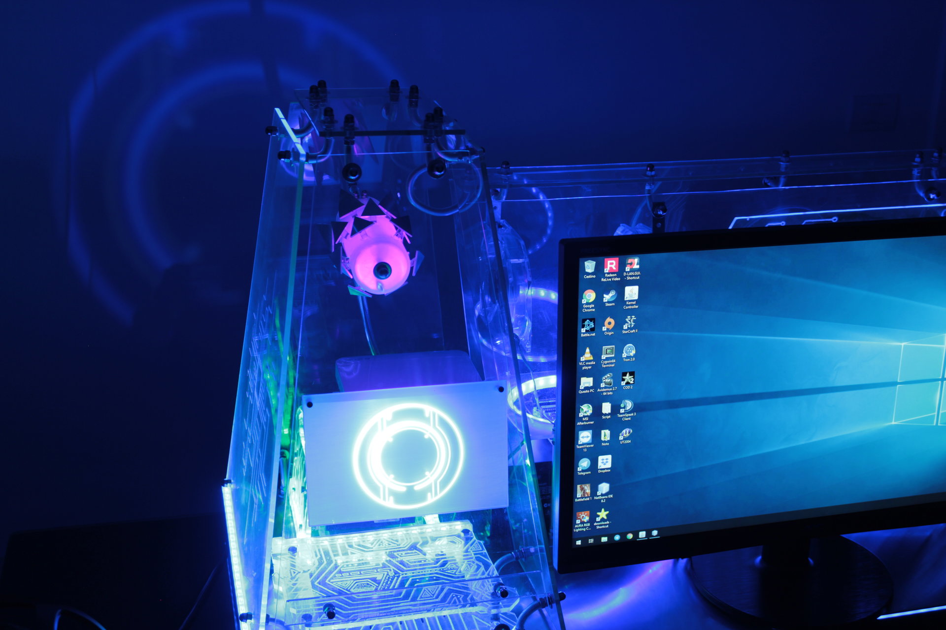
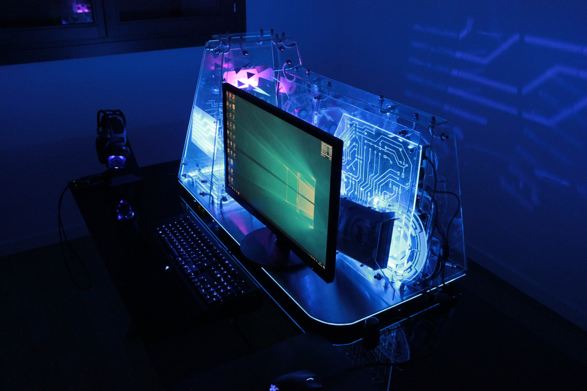
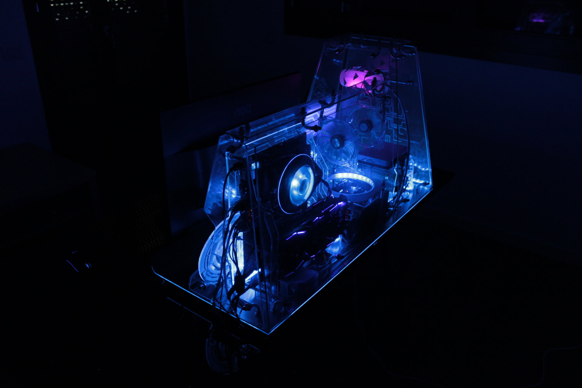
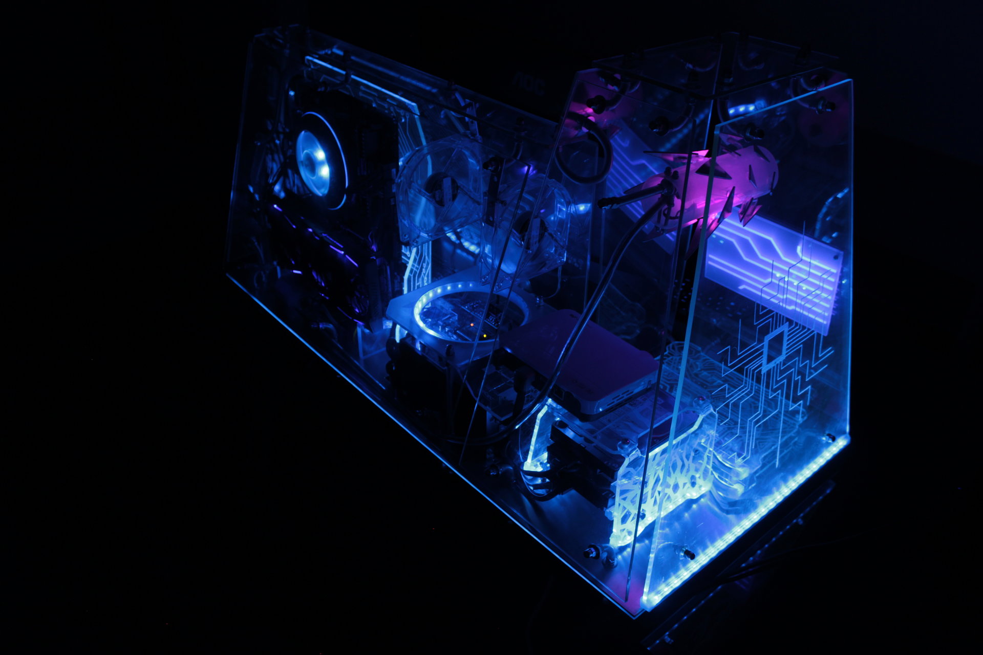
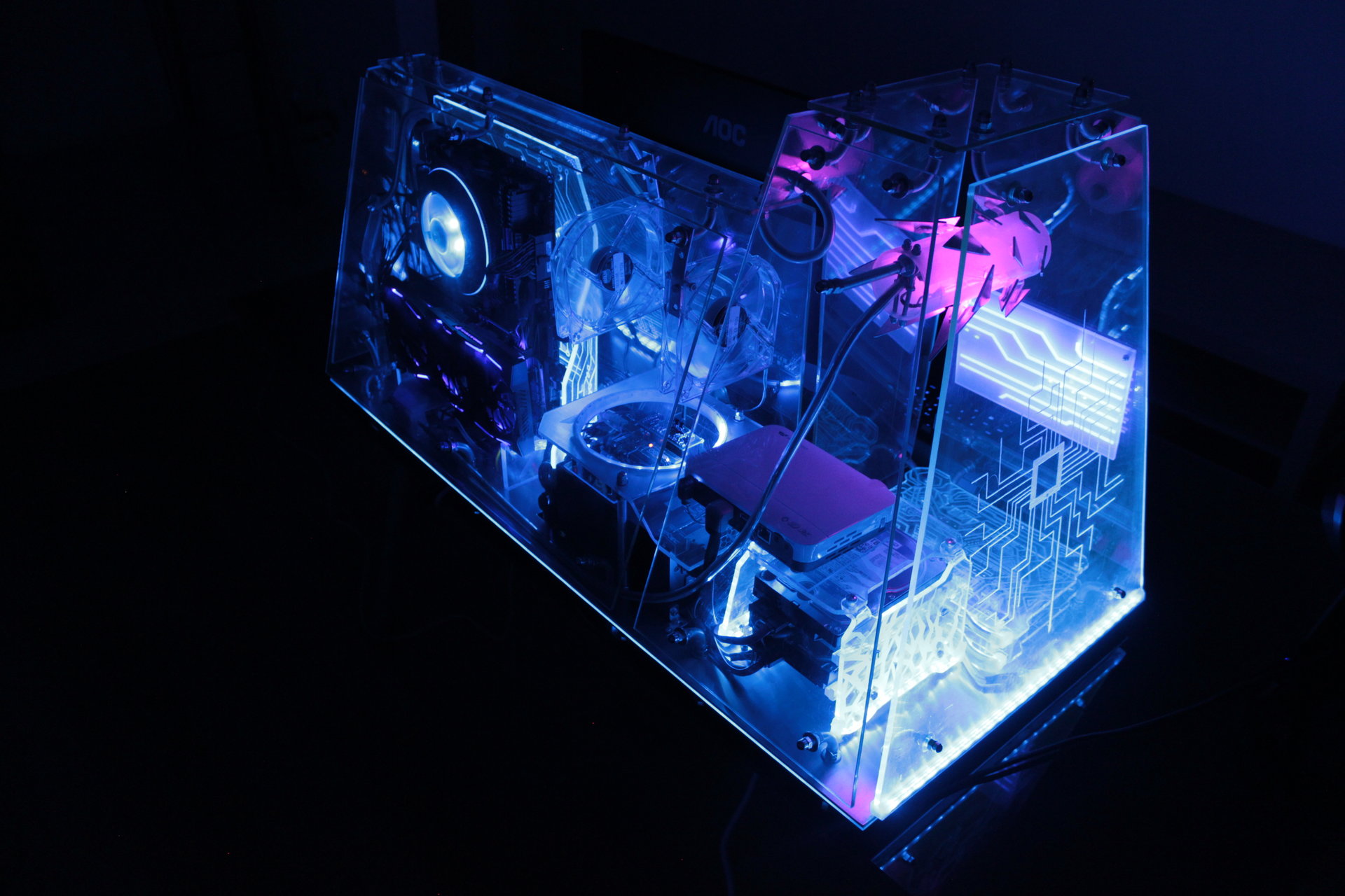
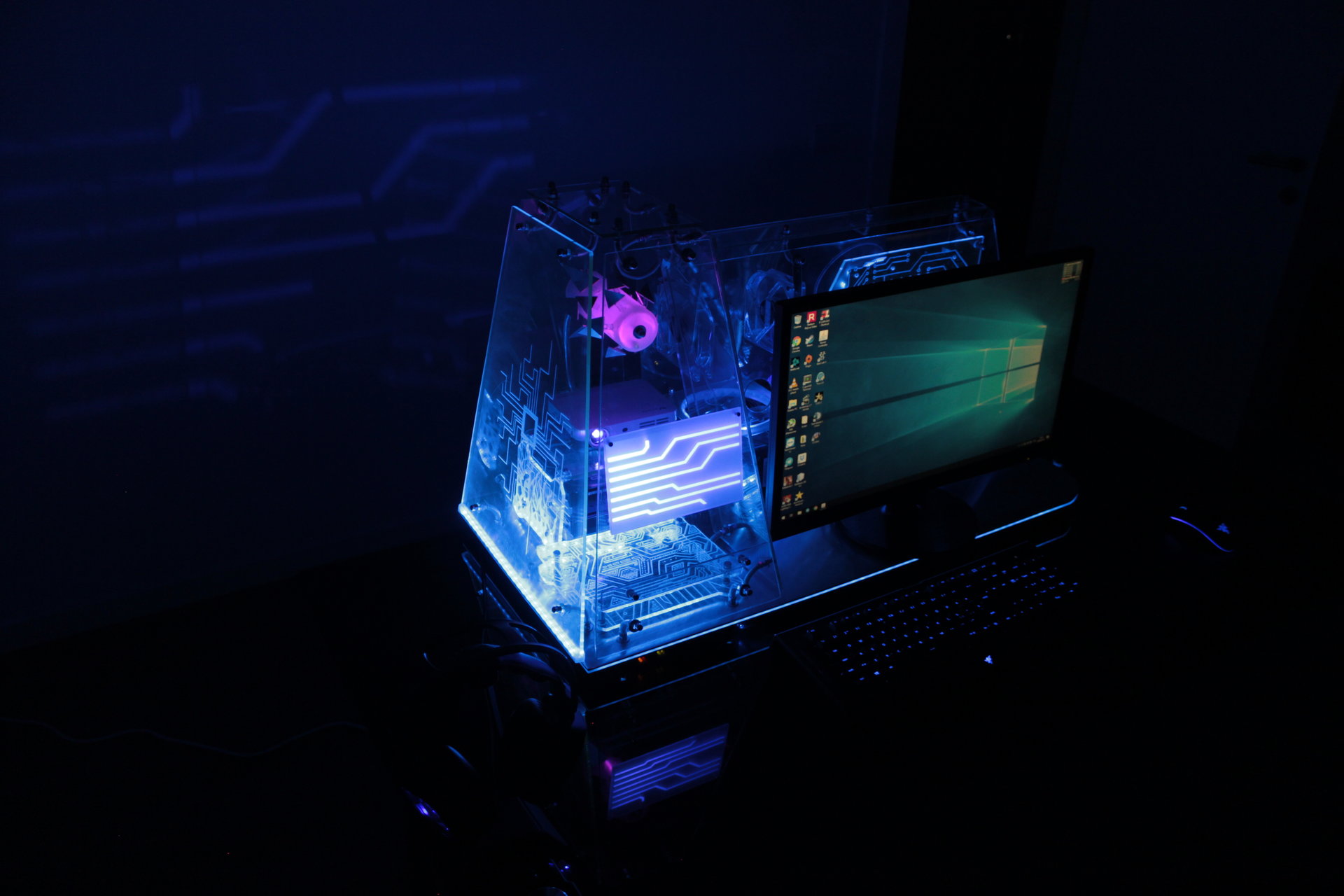
Default state 1:
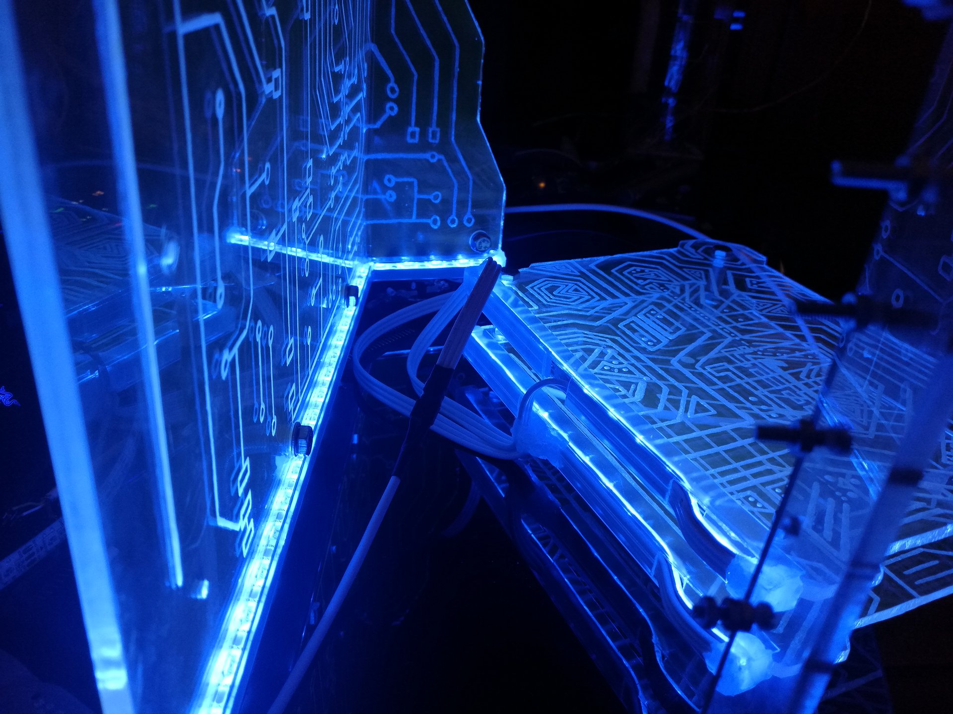
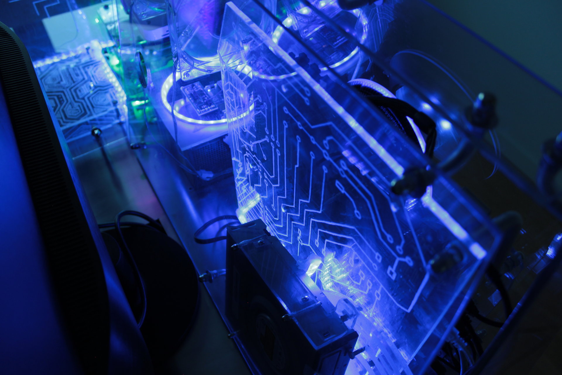
– mostly blue
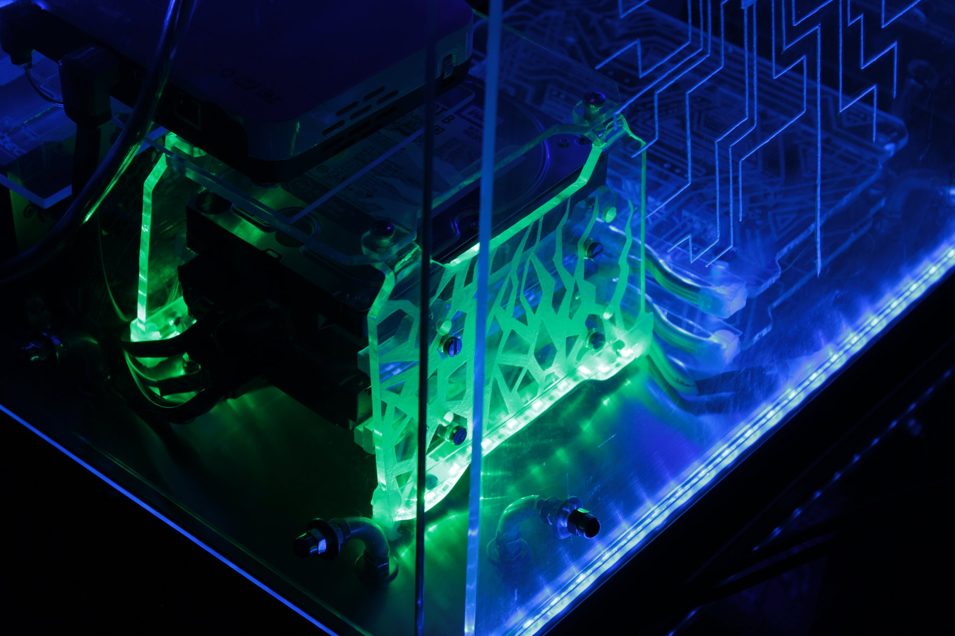
– infection effect that fades from blue to green on the hard disks
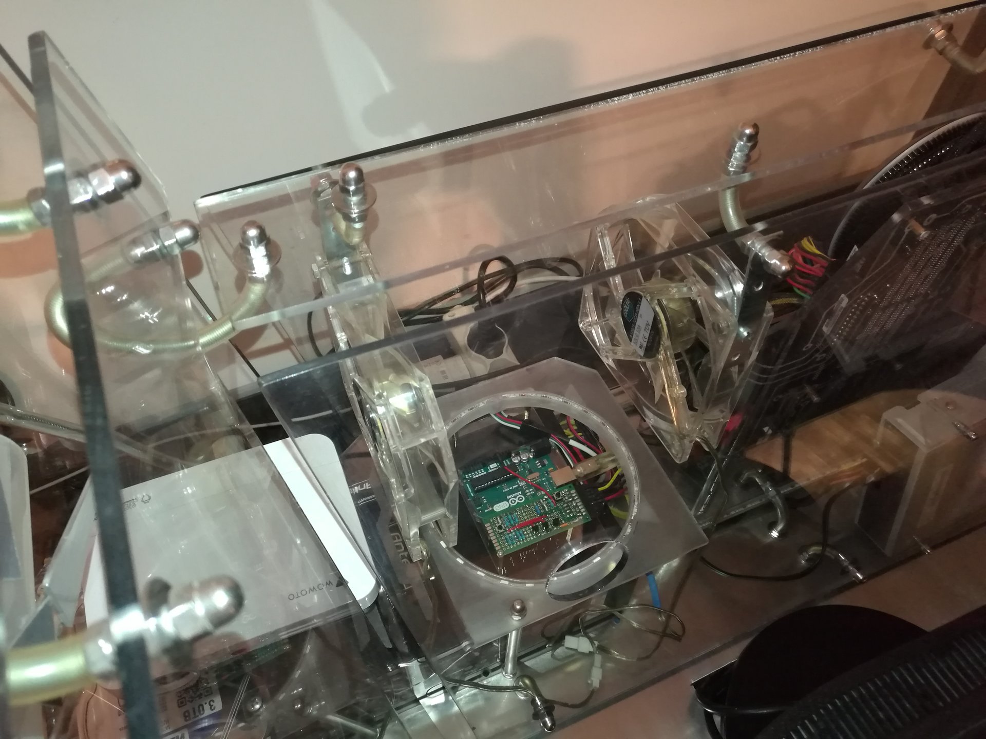
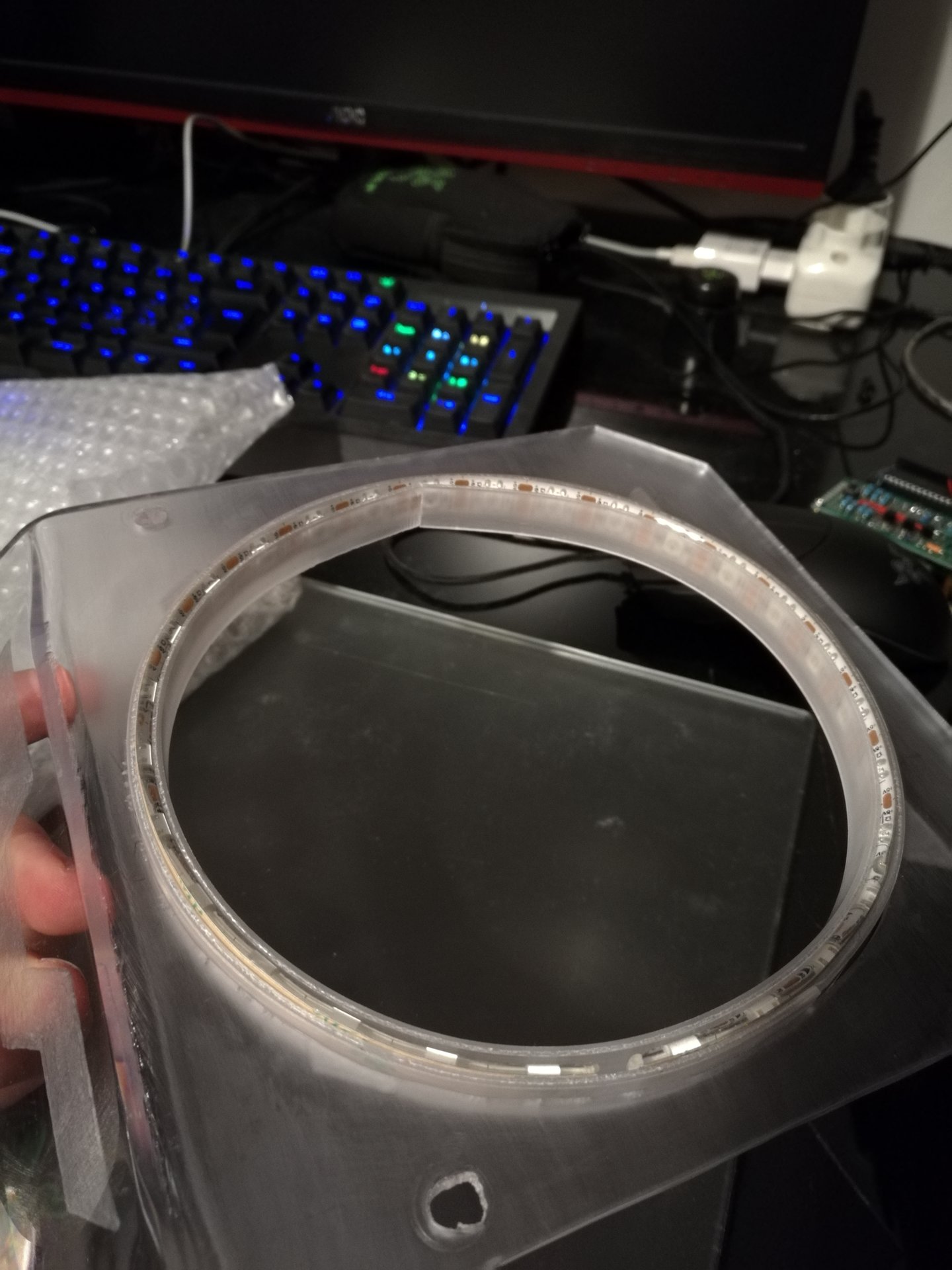
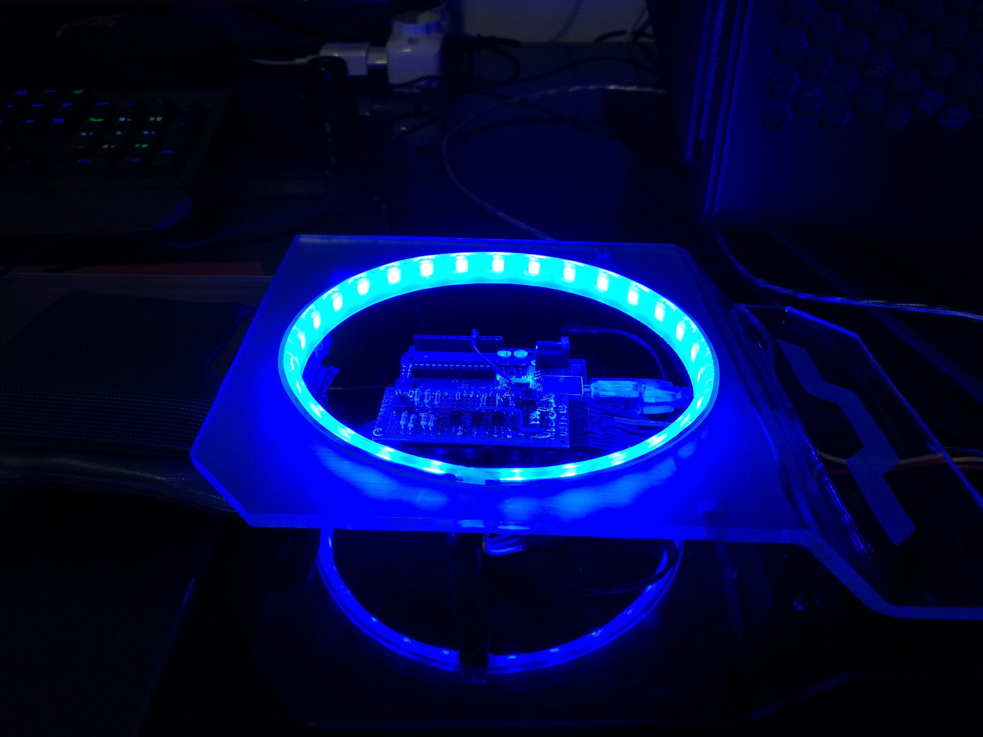
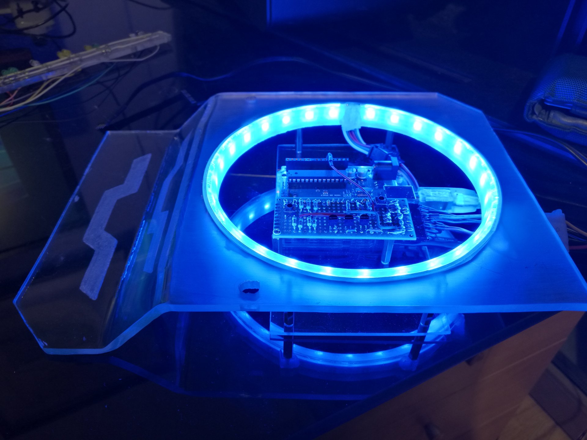
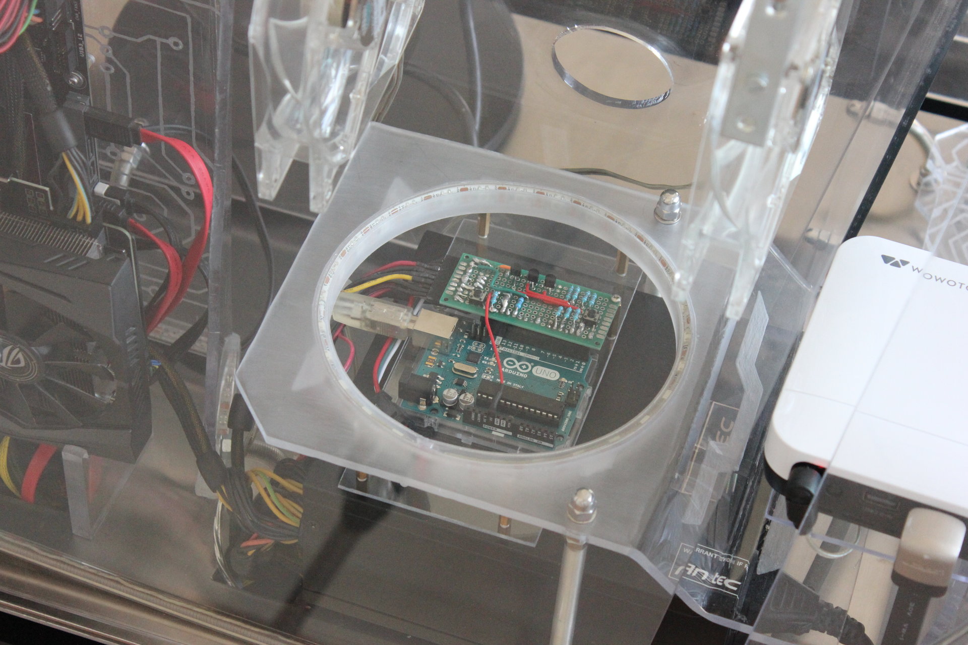
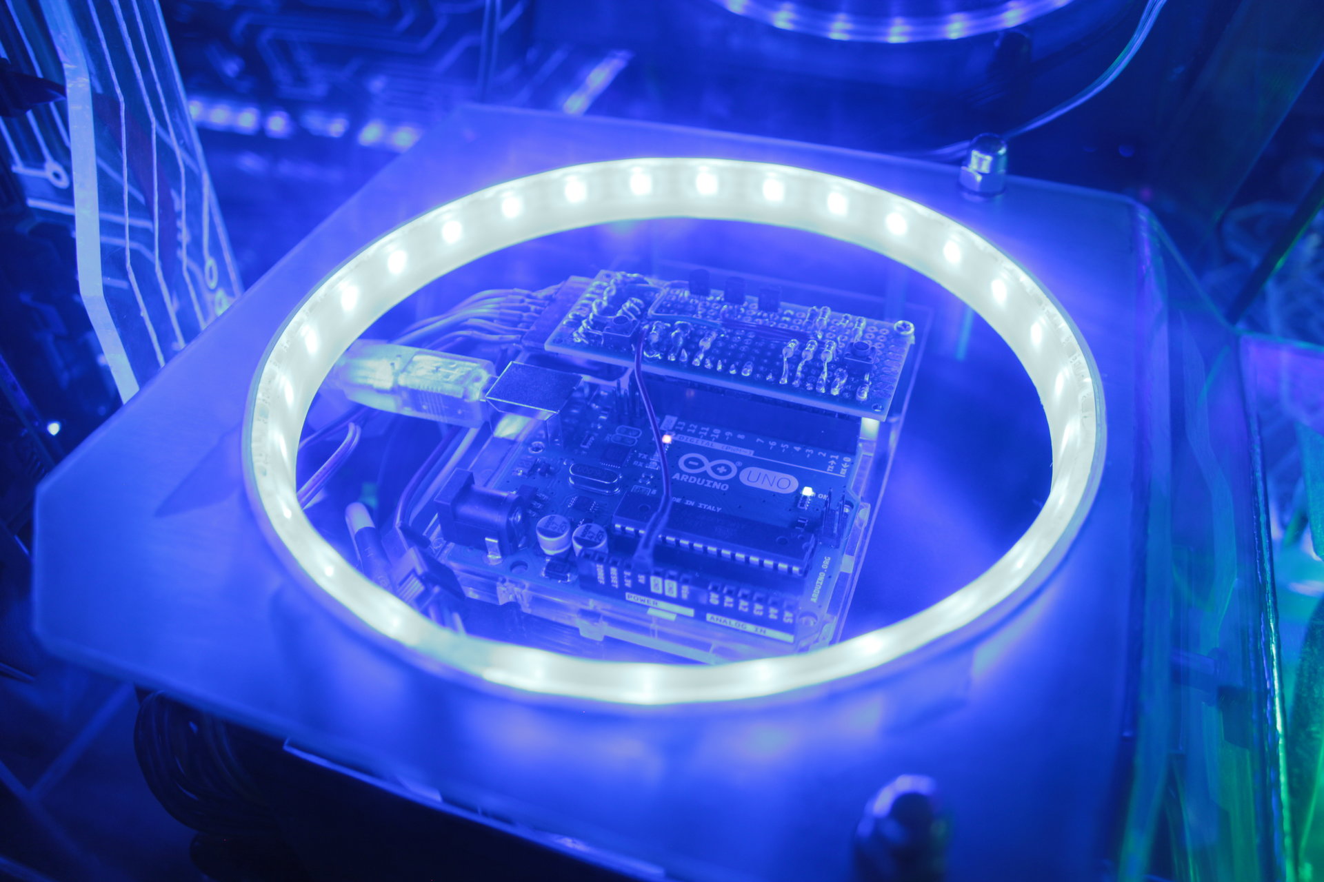
– Arduino ring with two rotating red pixel trails
– two yellow pixel trails that run around the base
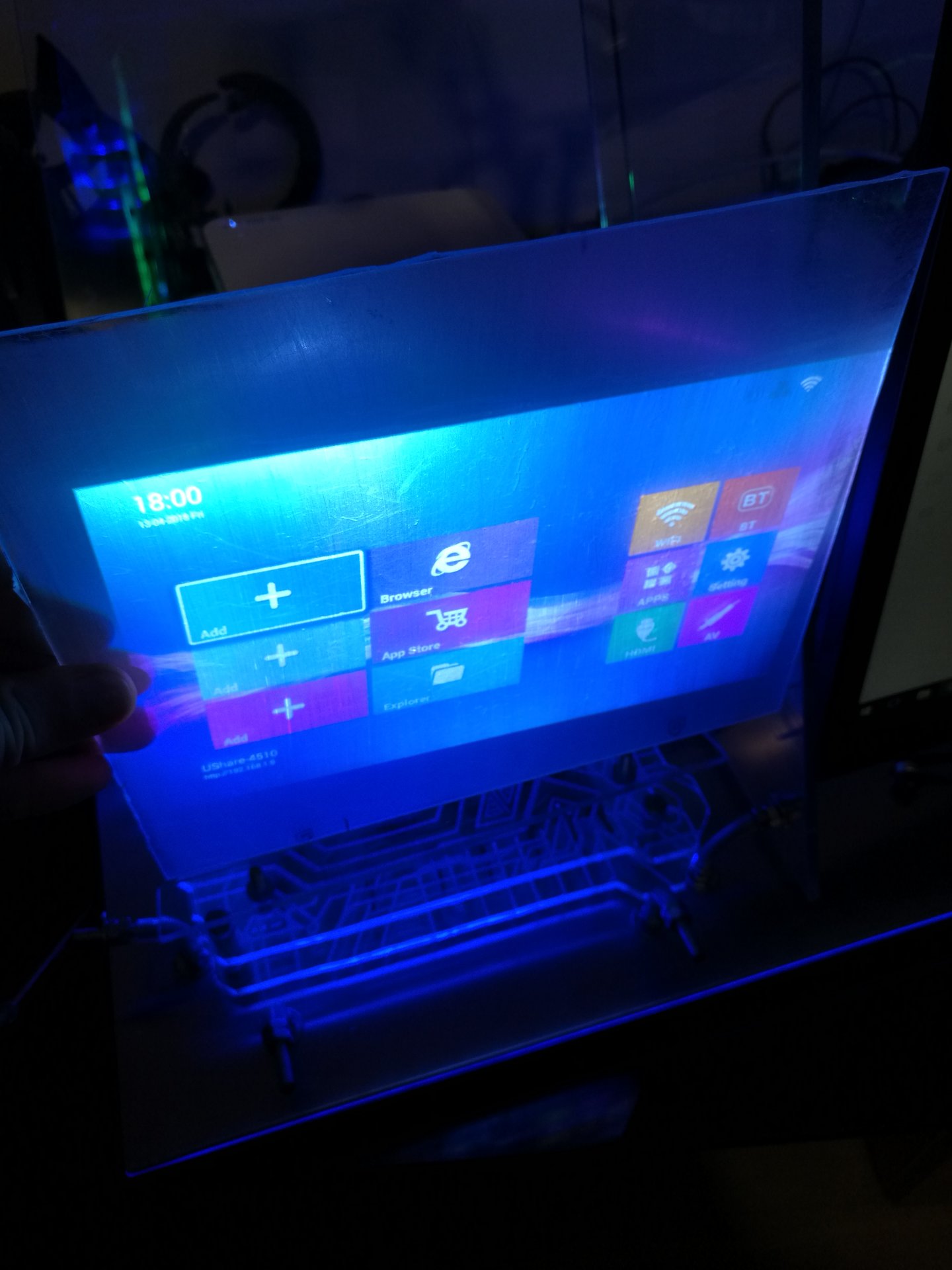
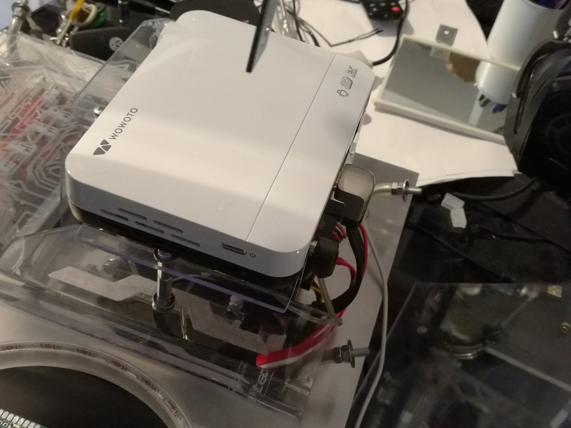
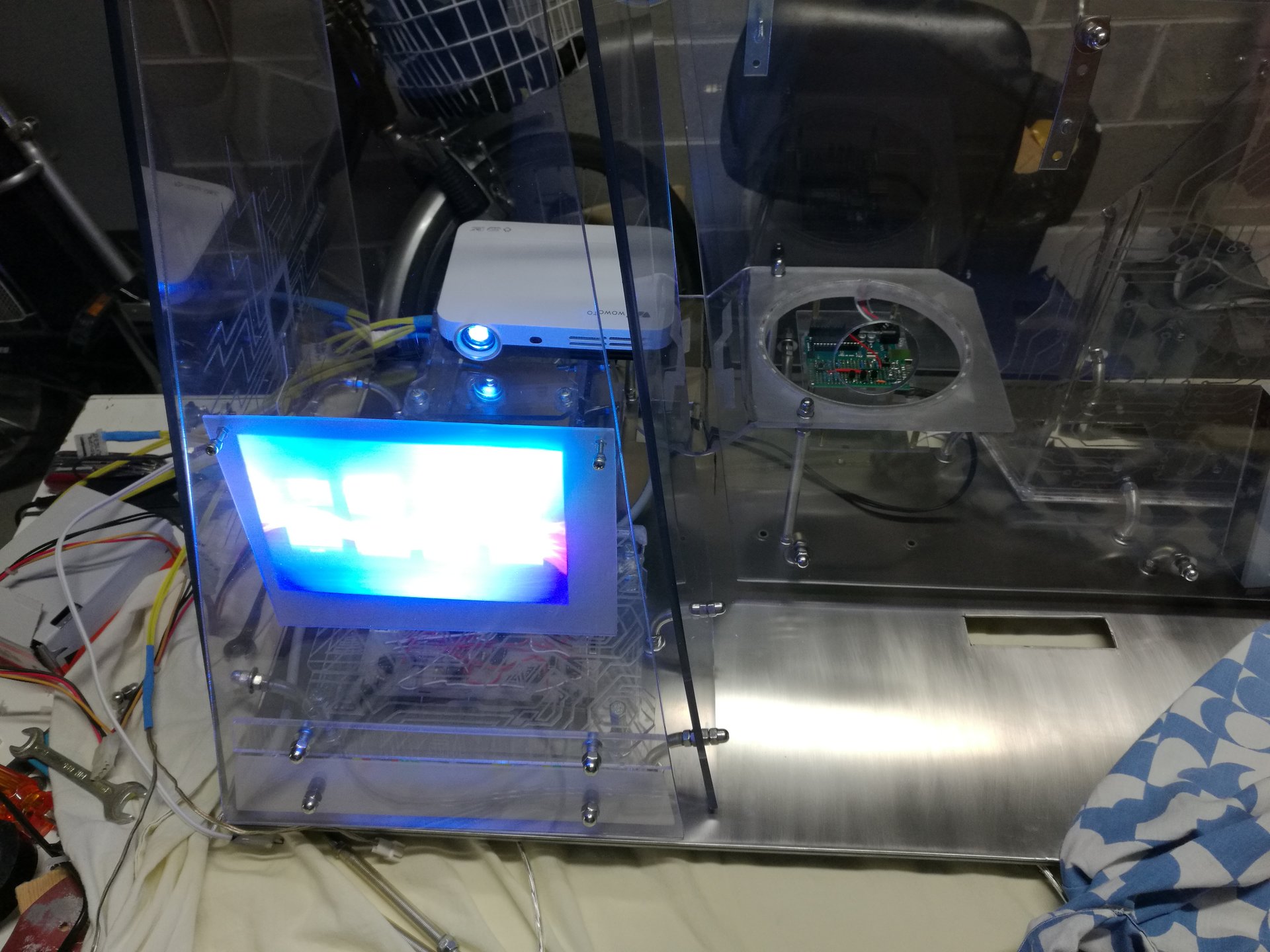
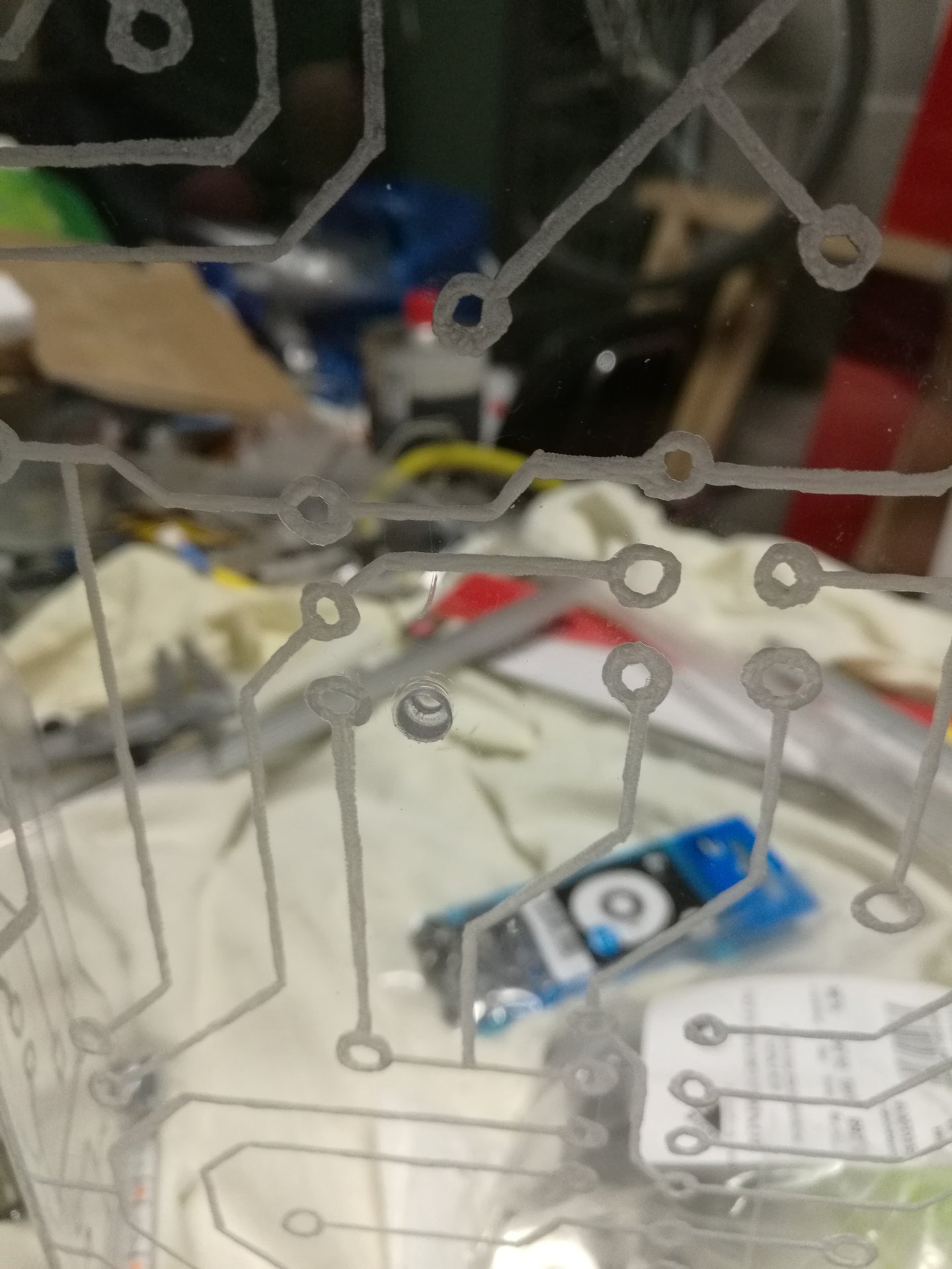
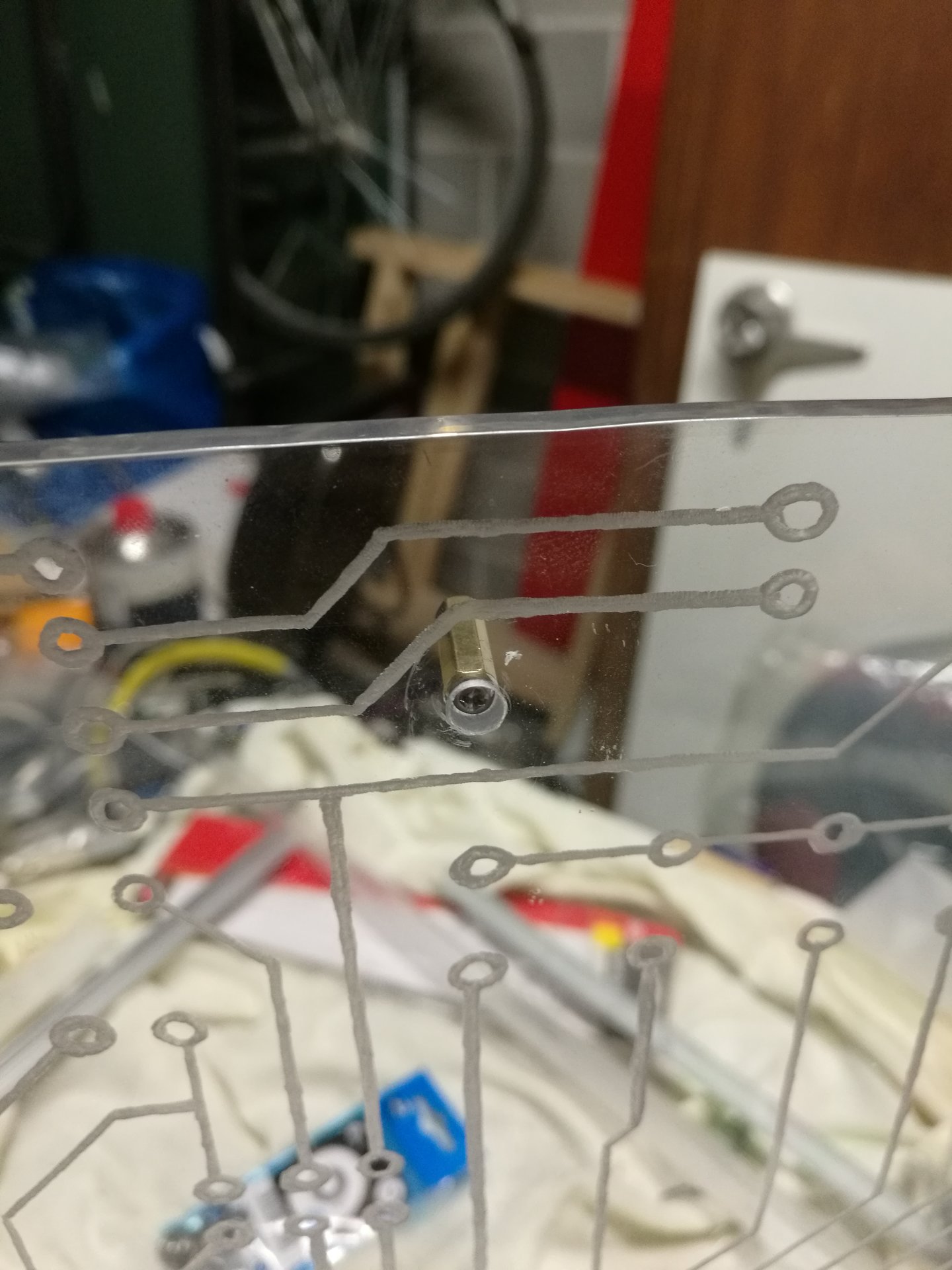
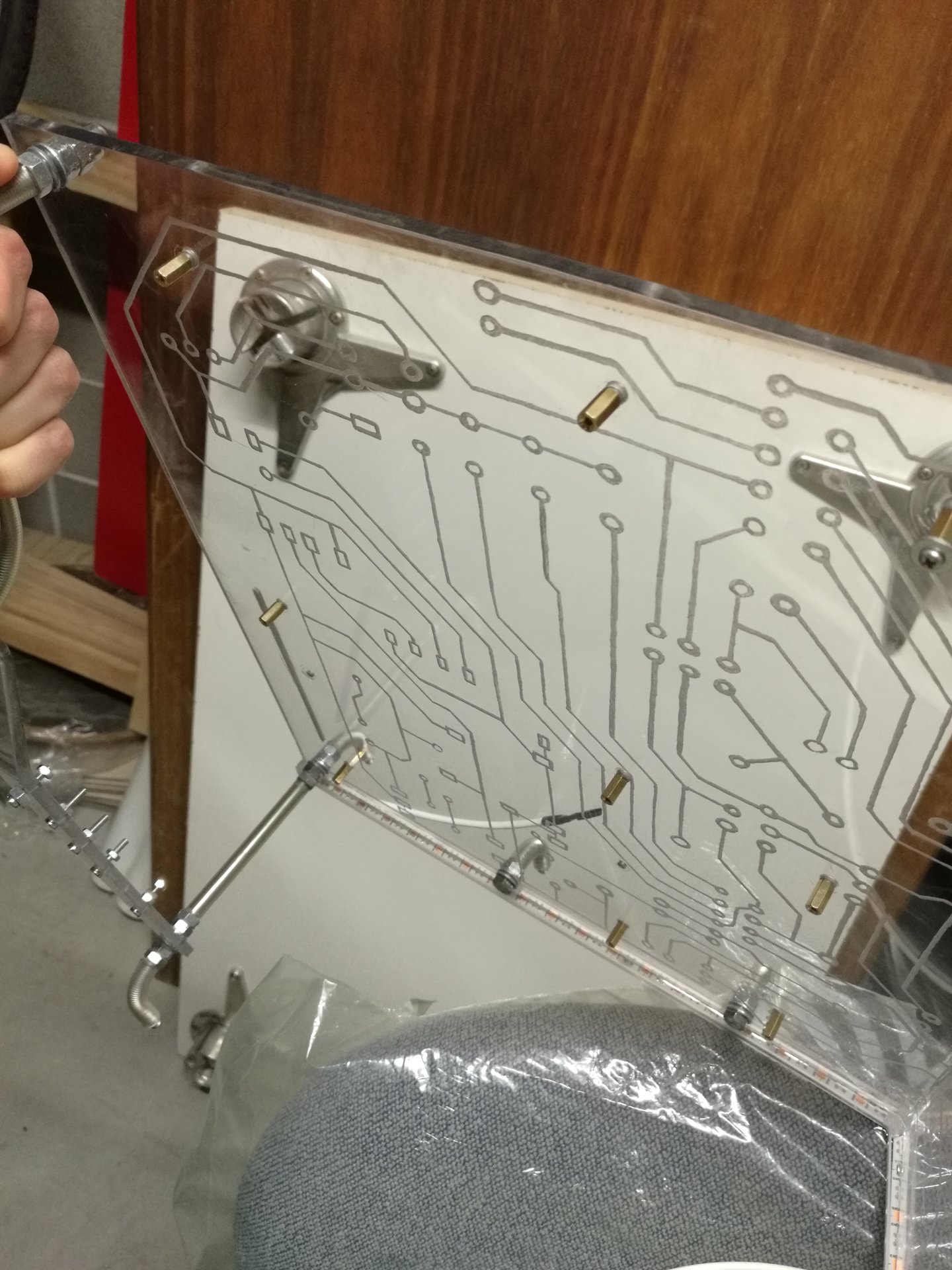
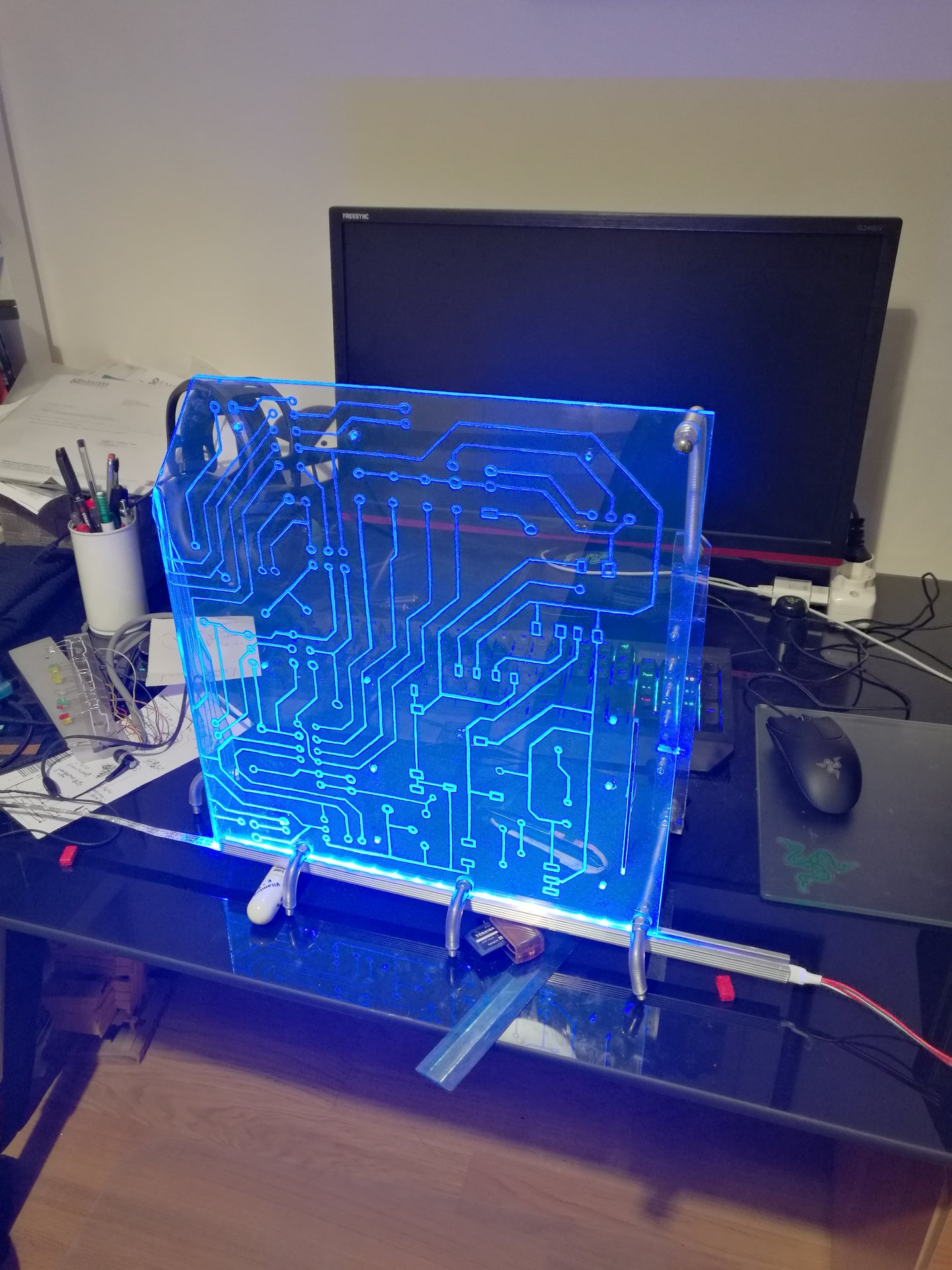
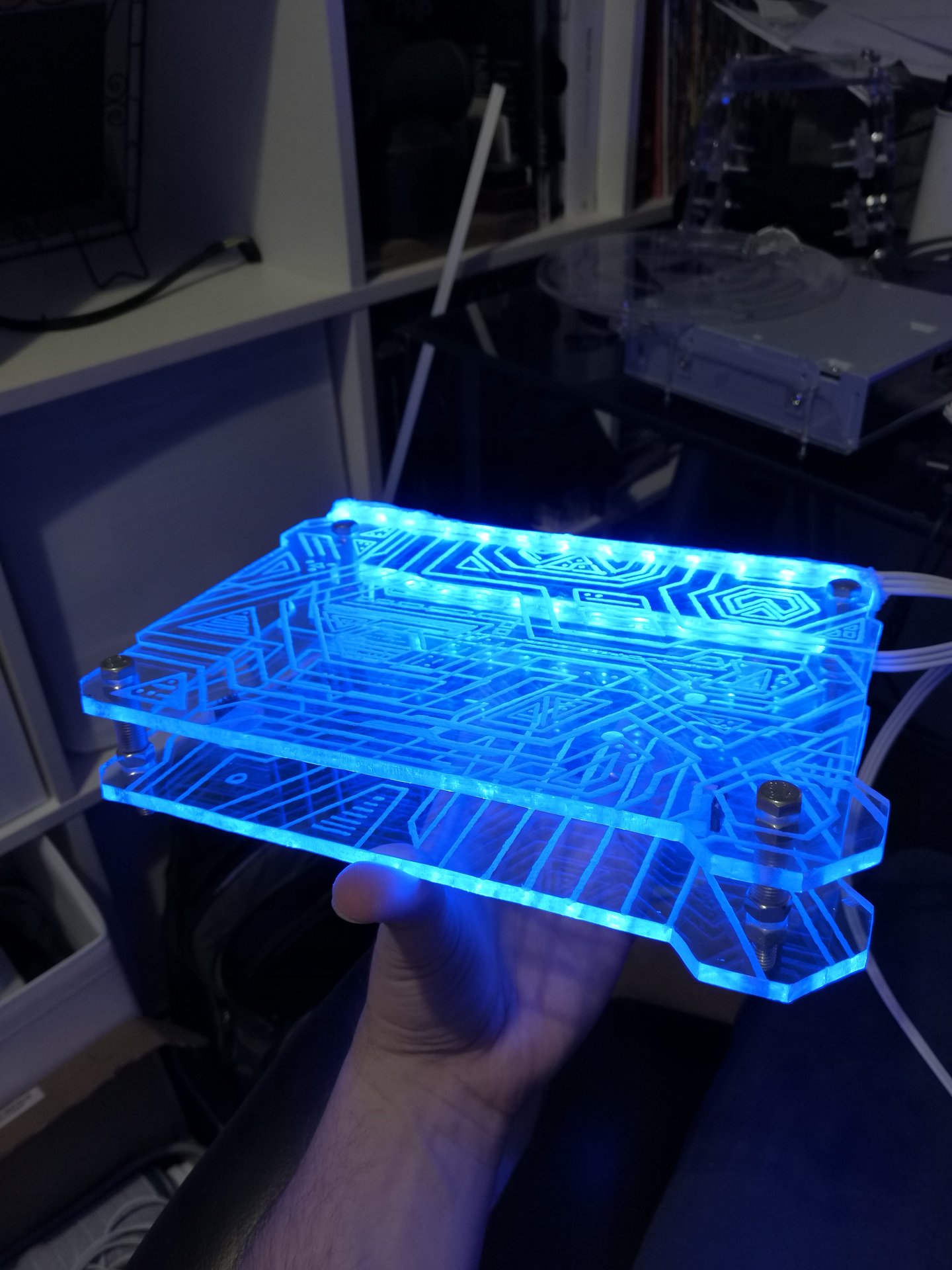
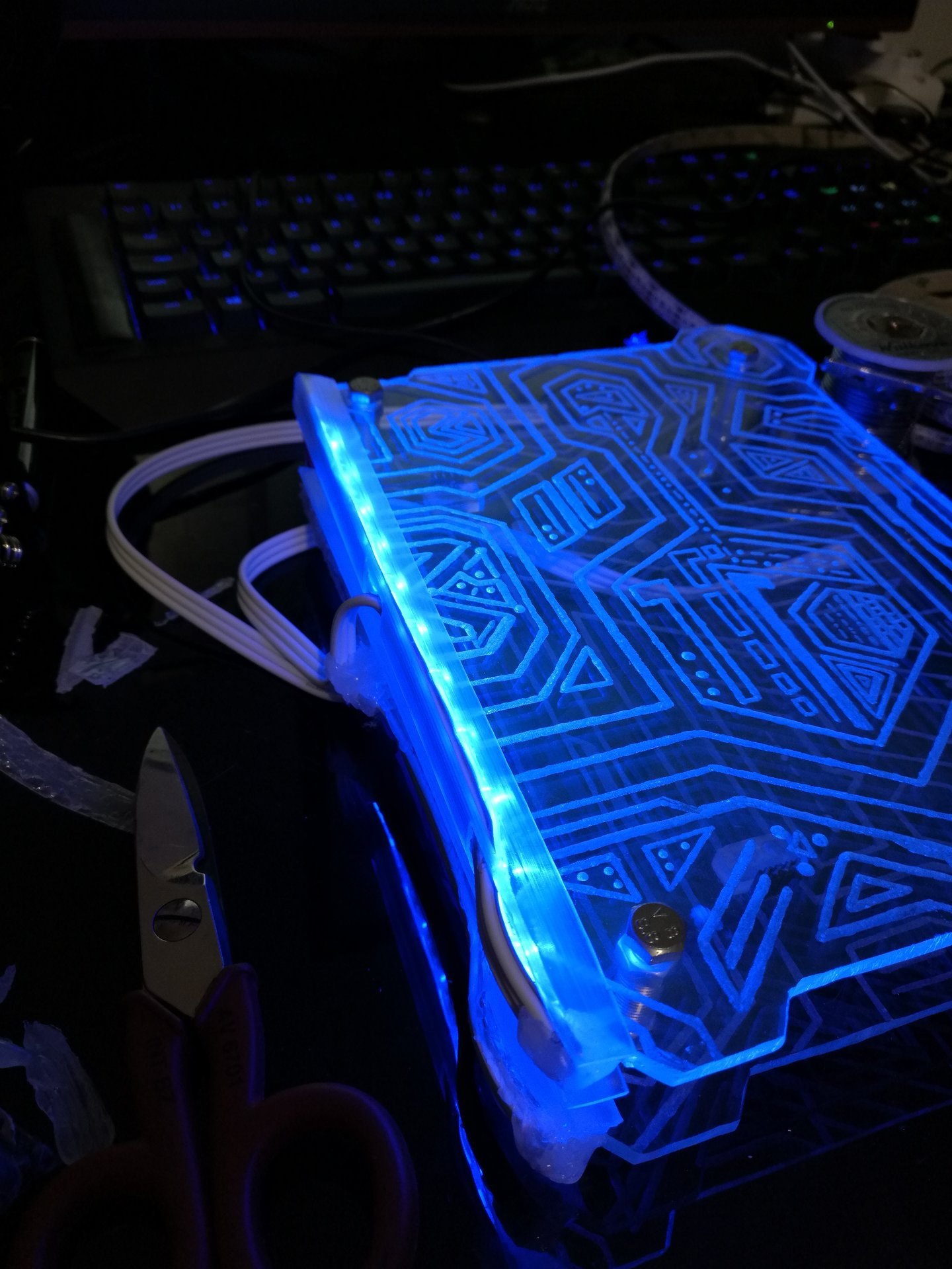
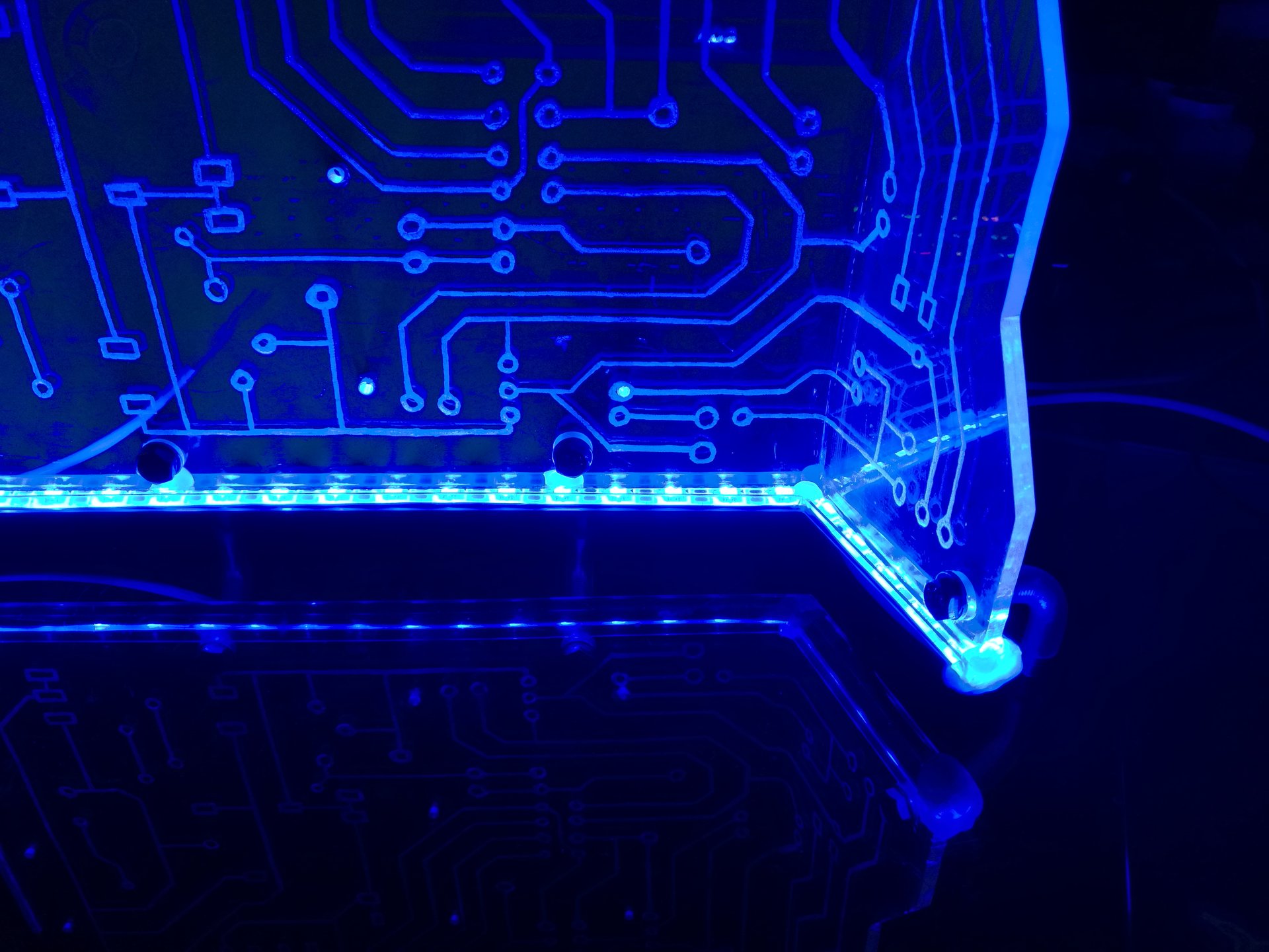
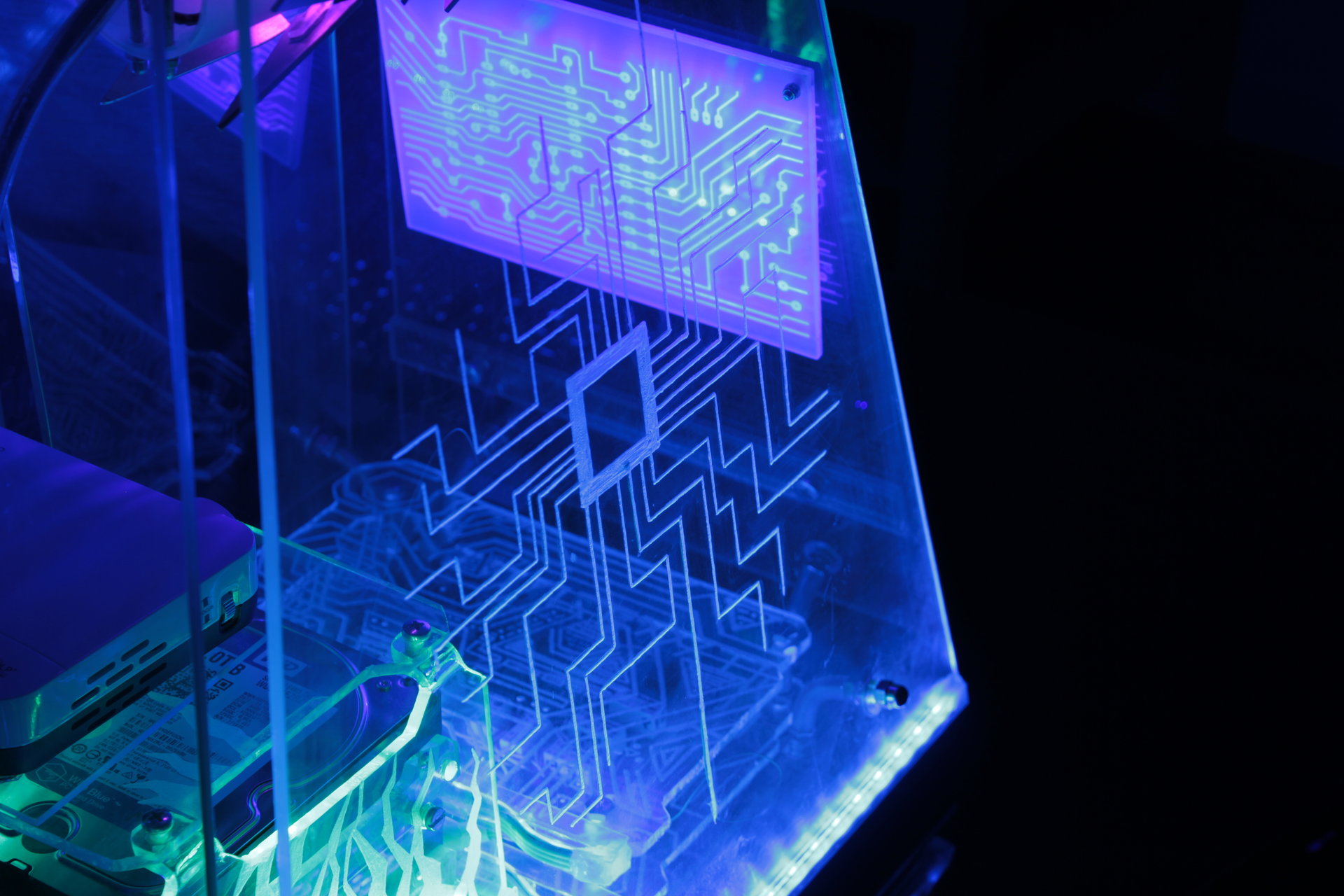
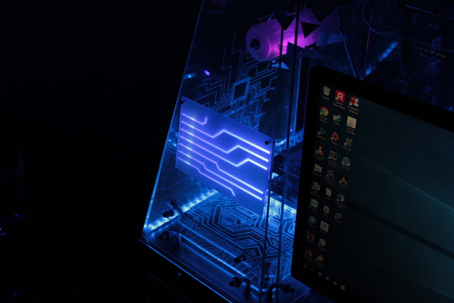
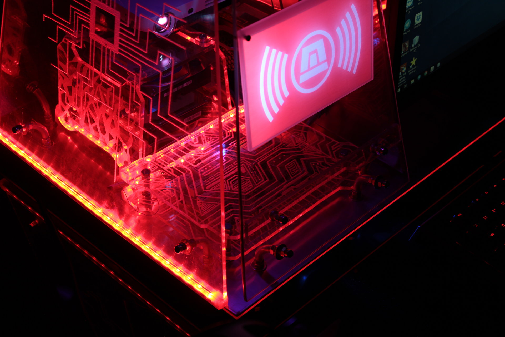
– projector animation: blue electronic circuit
– proximity sensor “charging” effect: blue->green->yellow->red
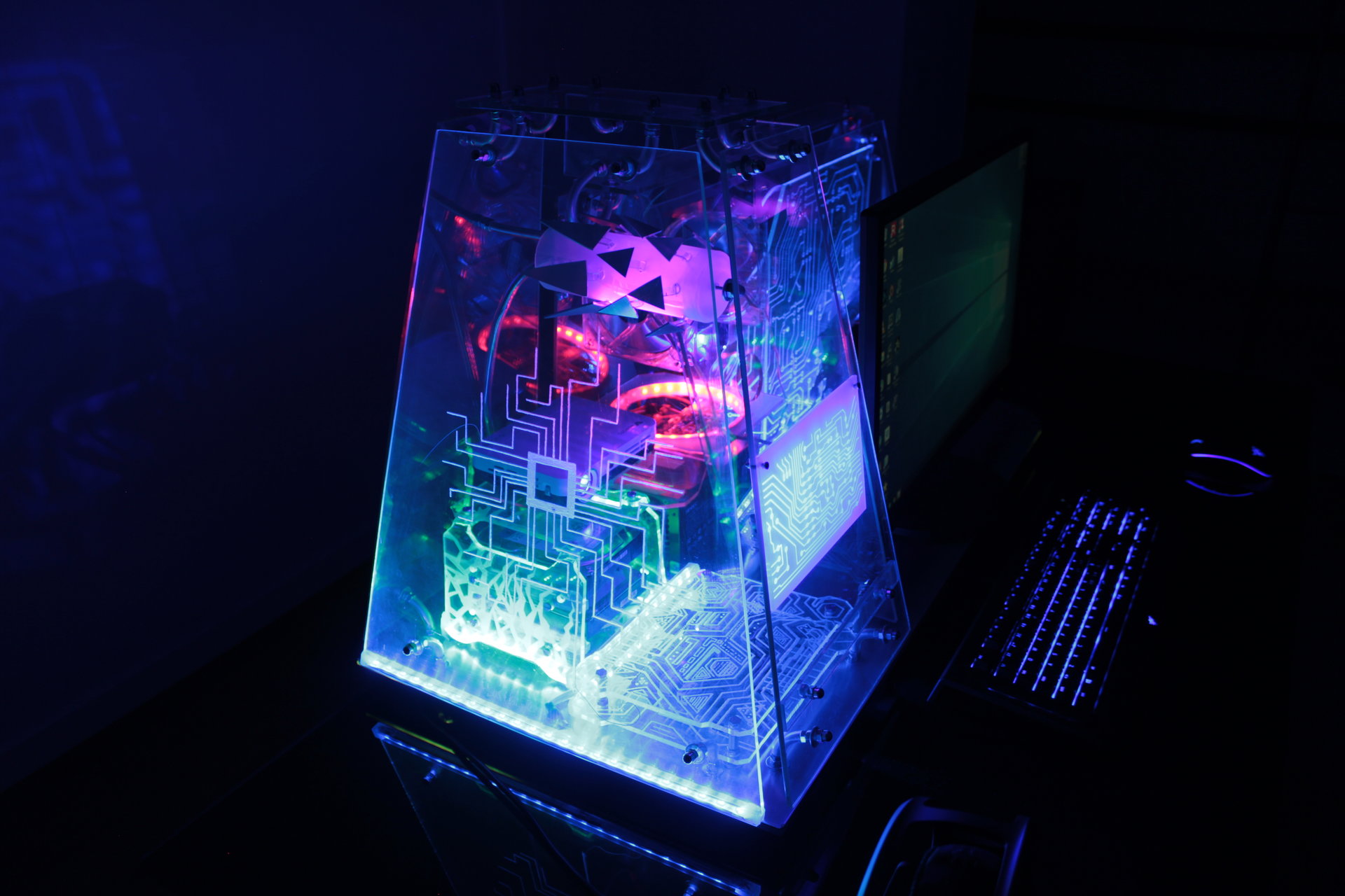

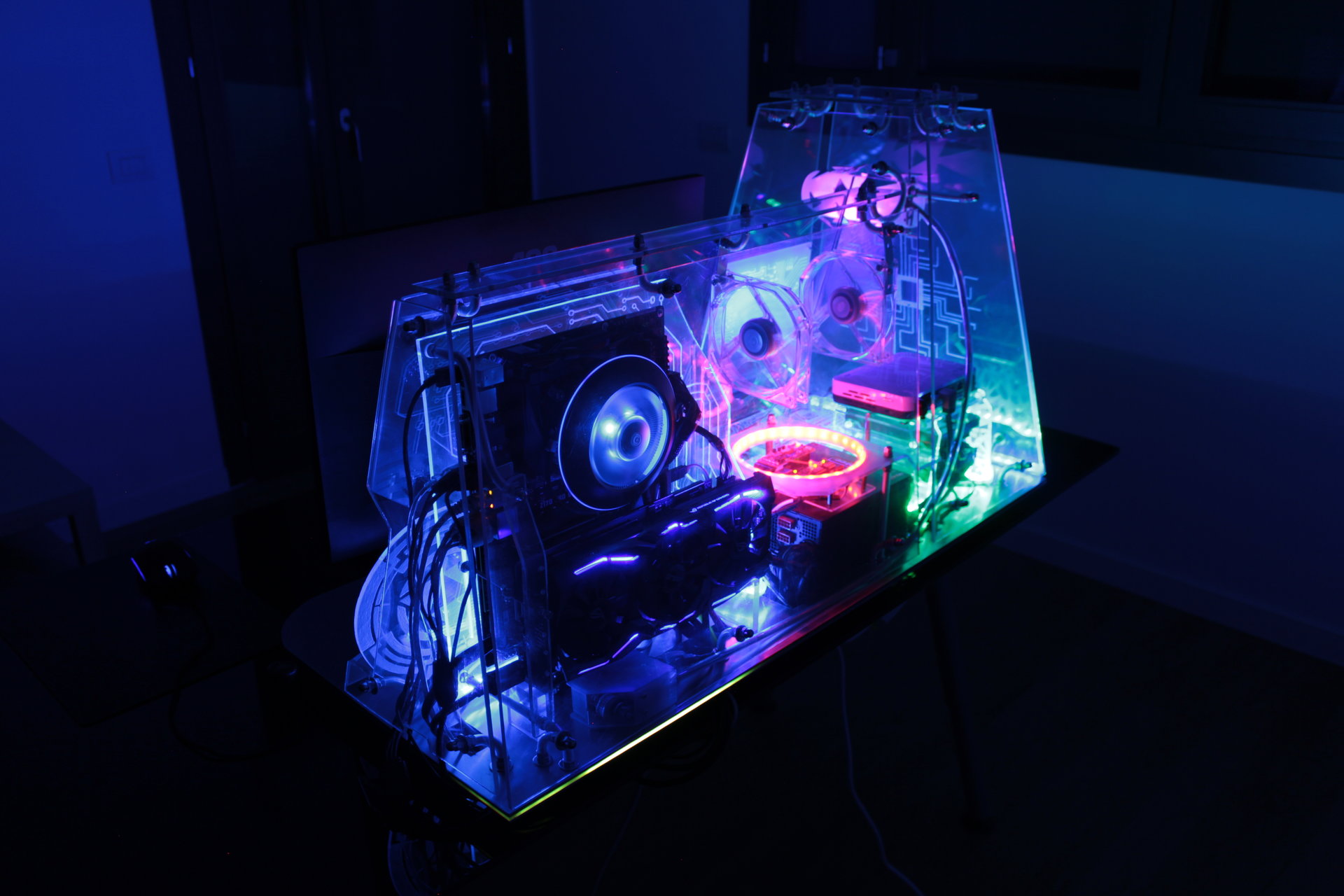
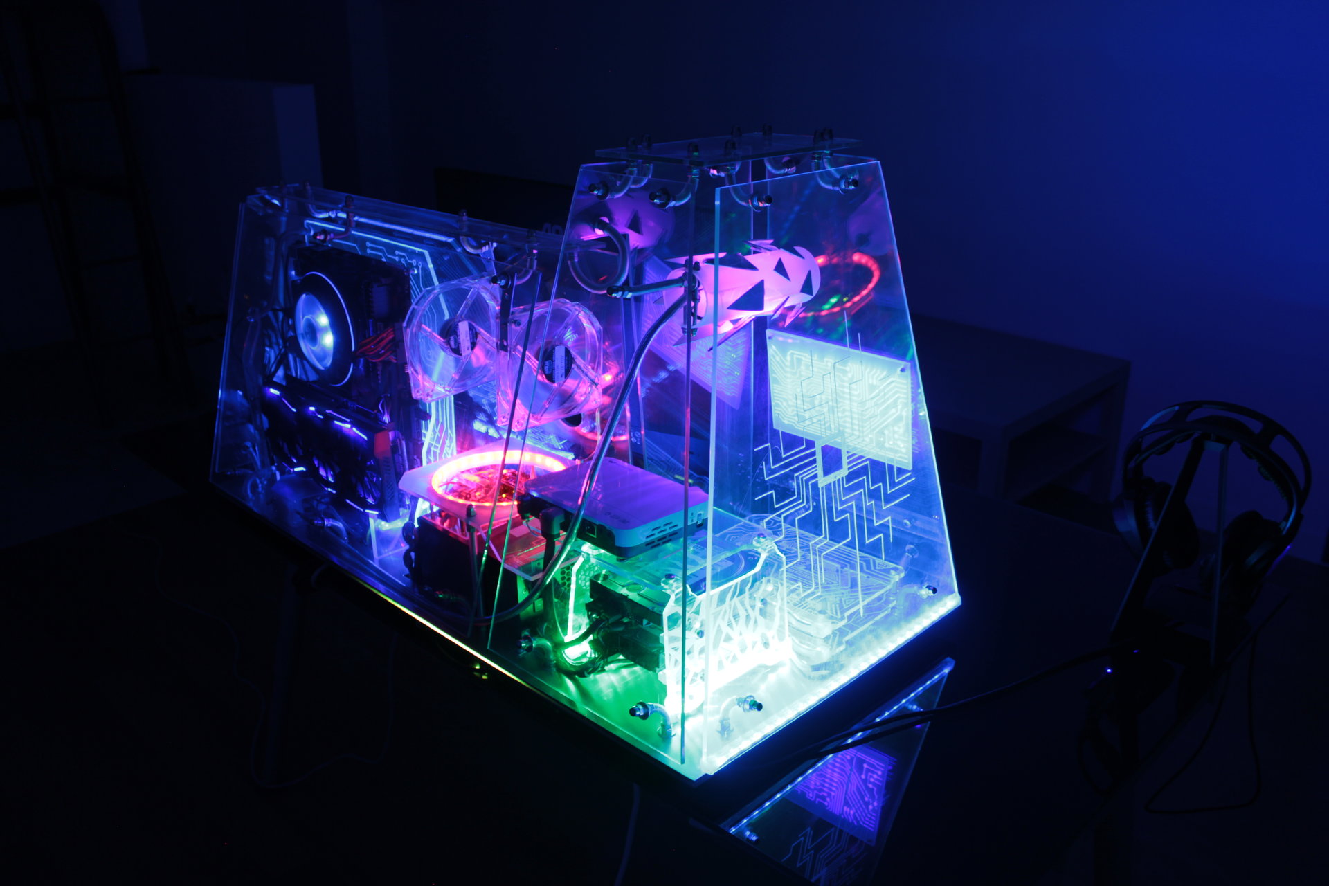


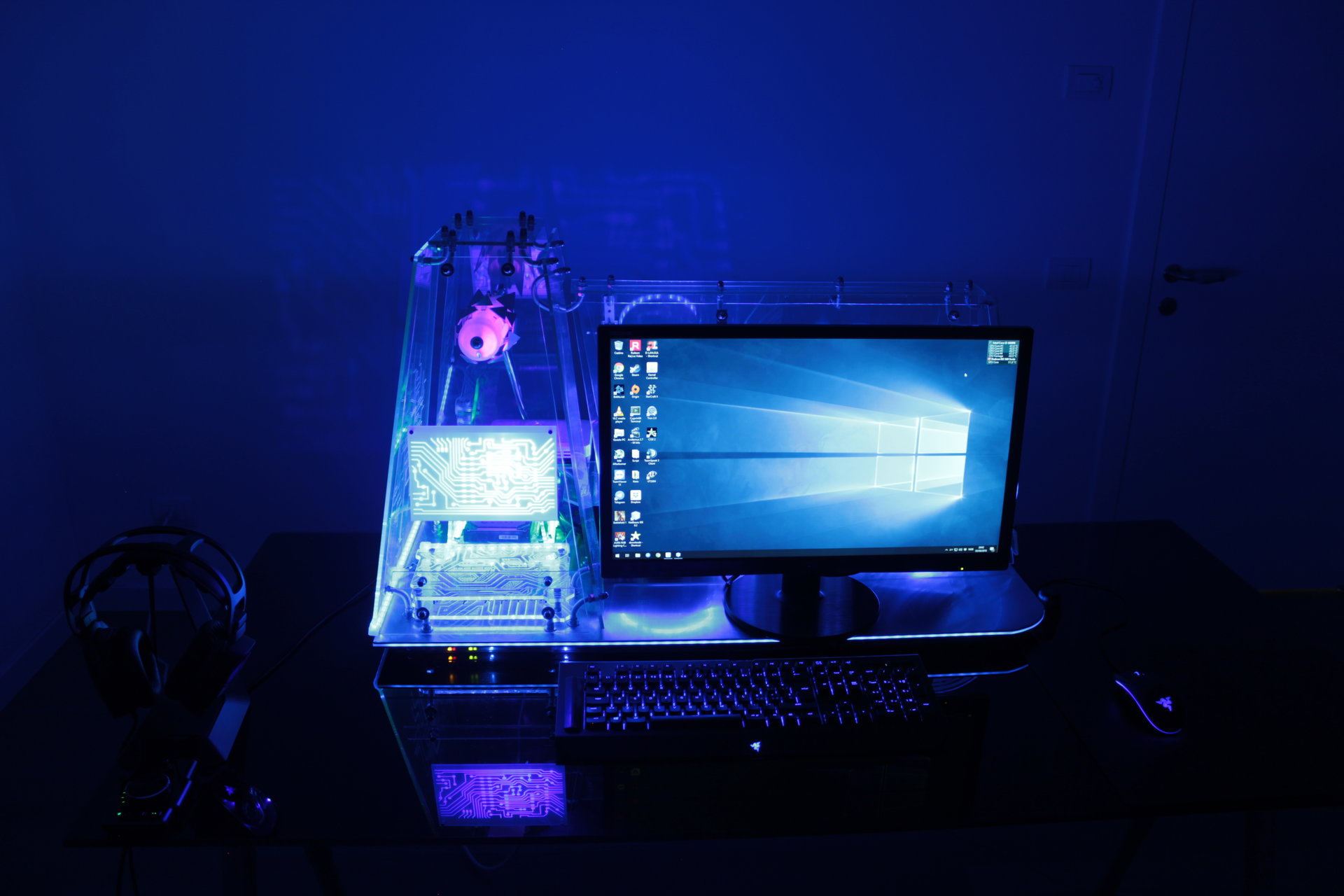
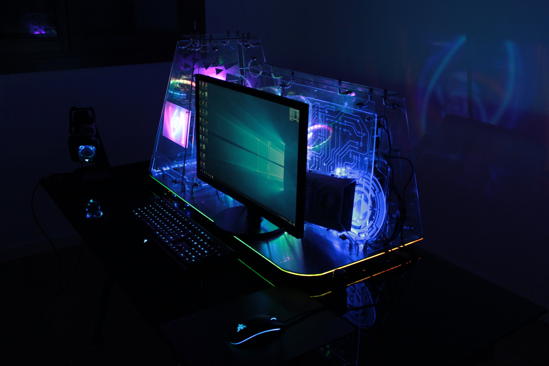
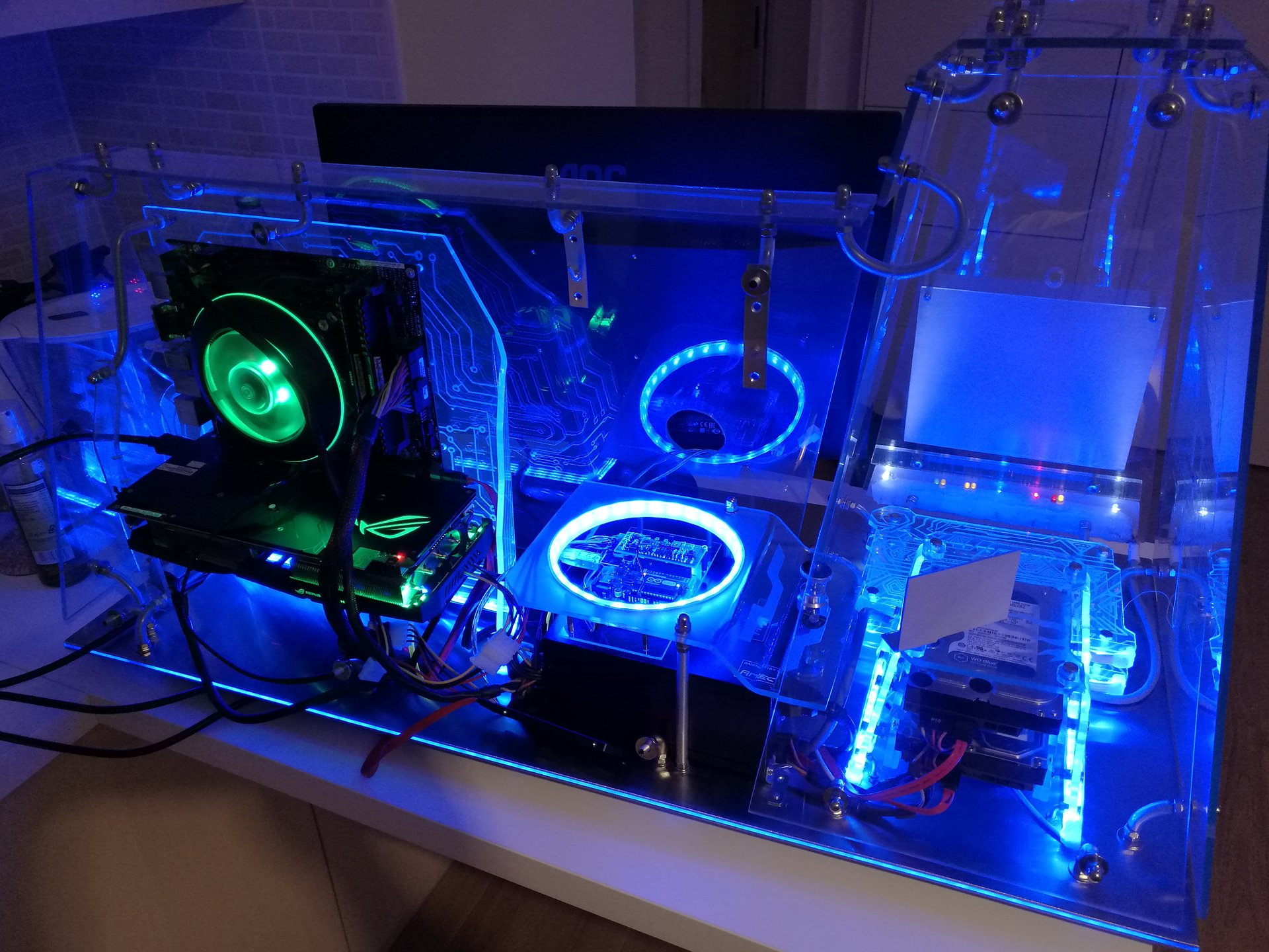
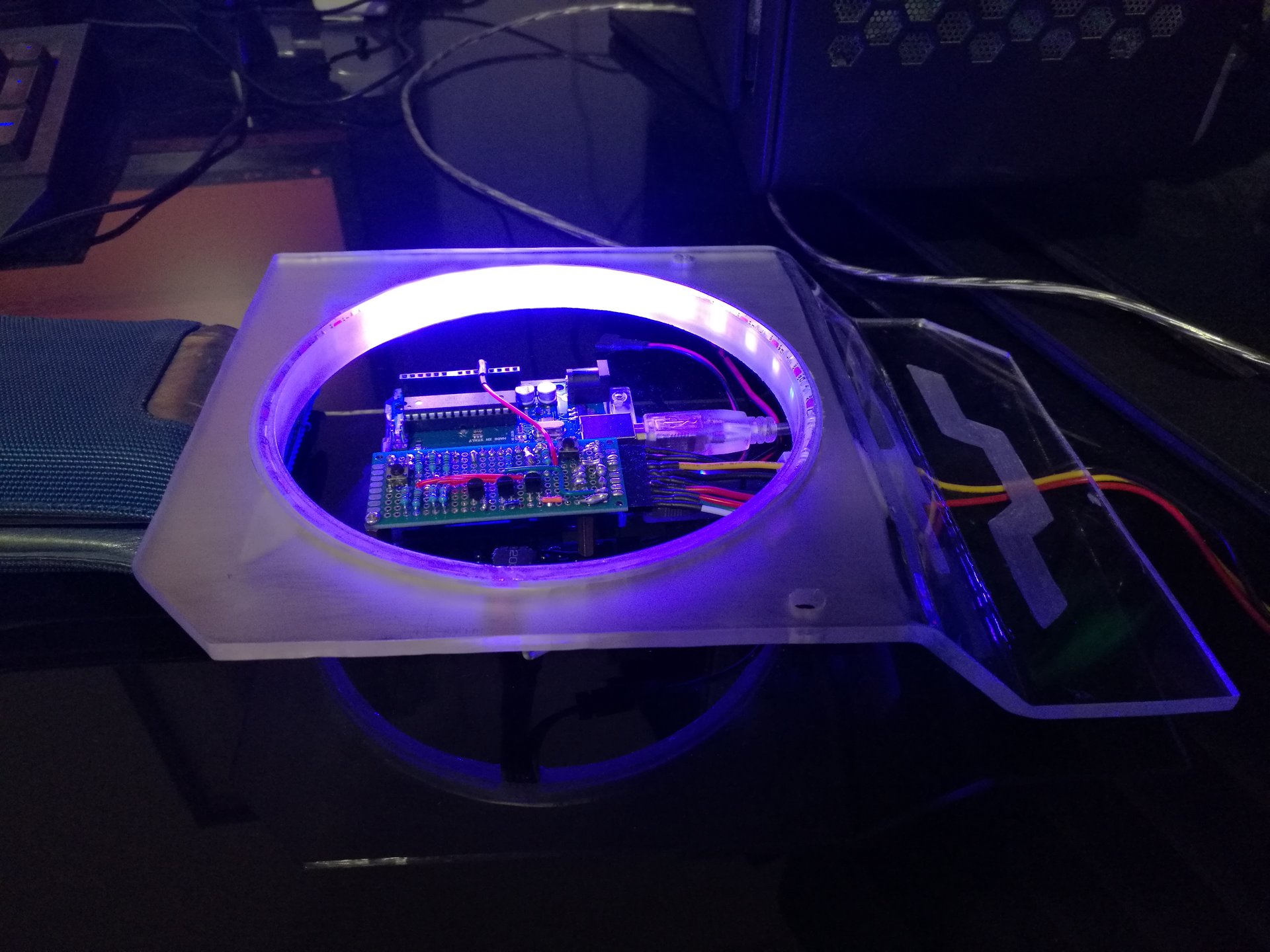
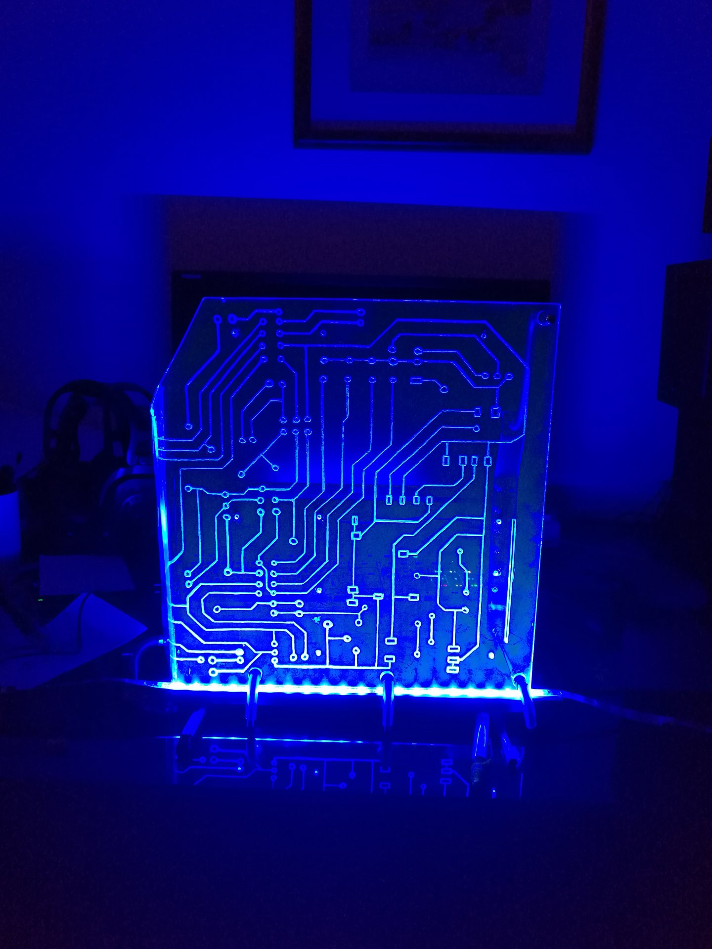
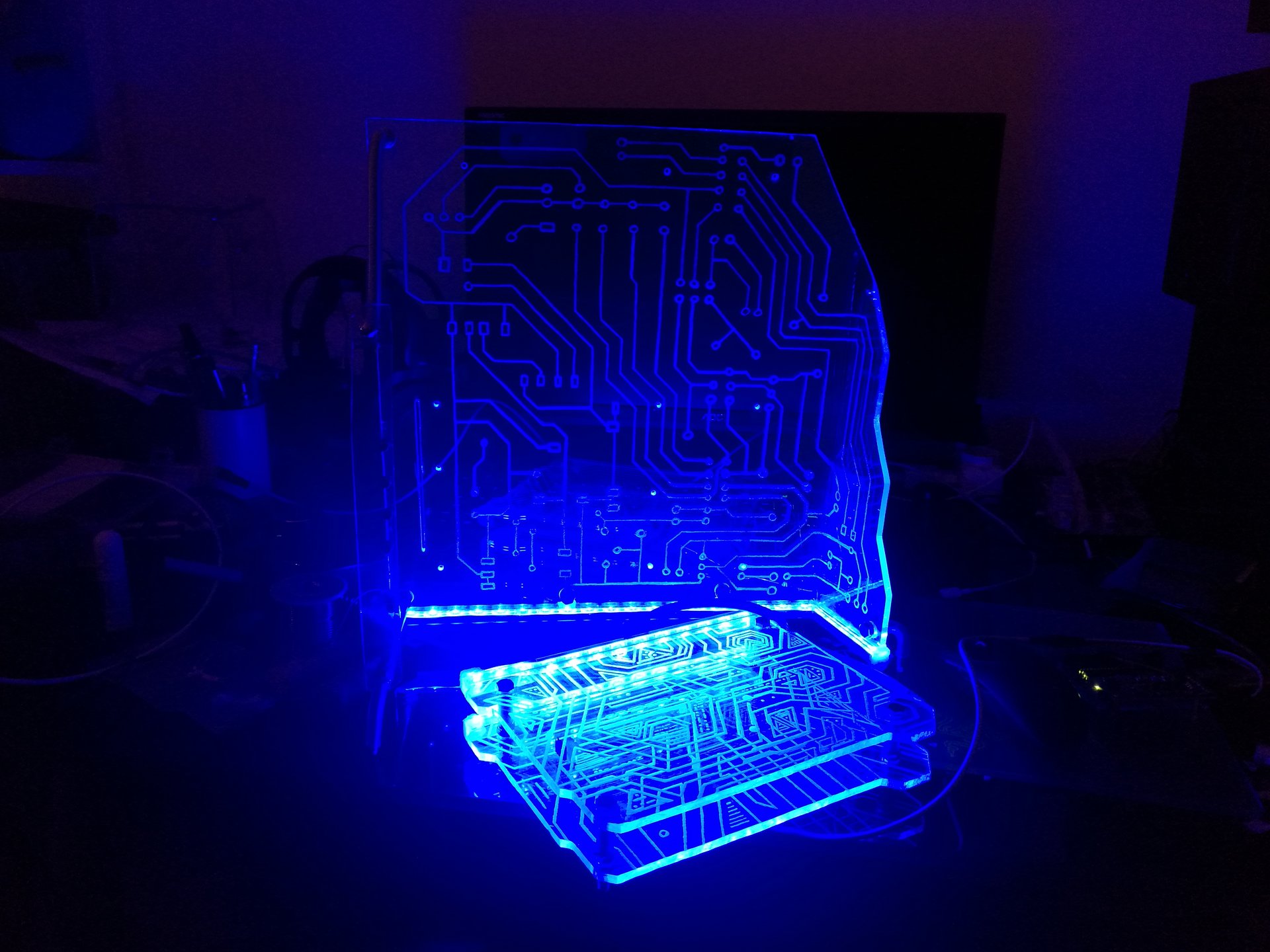
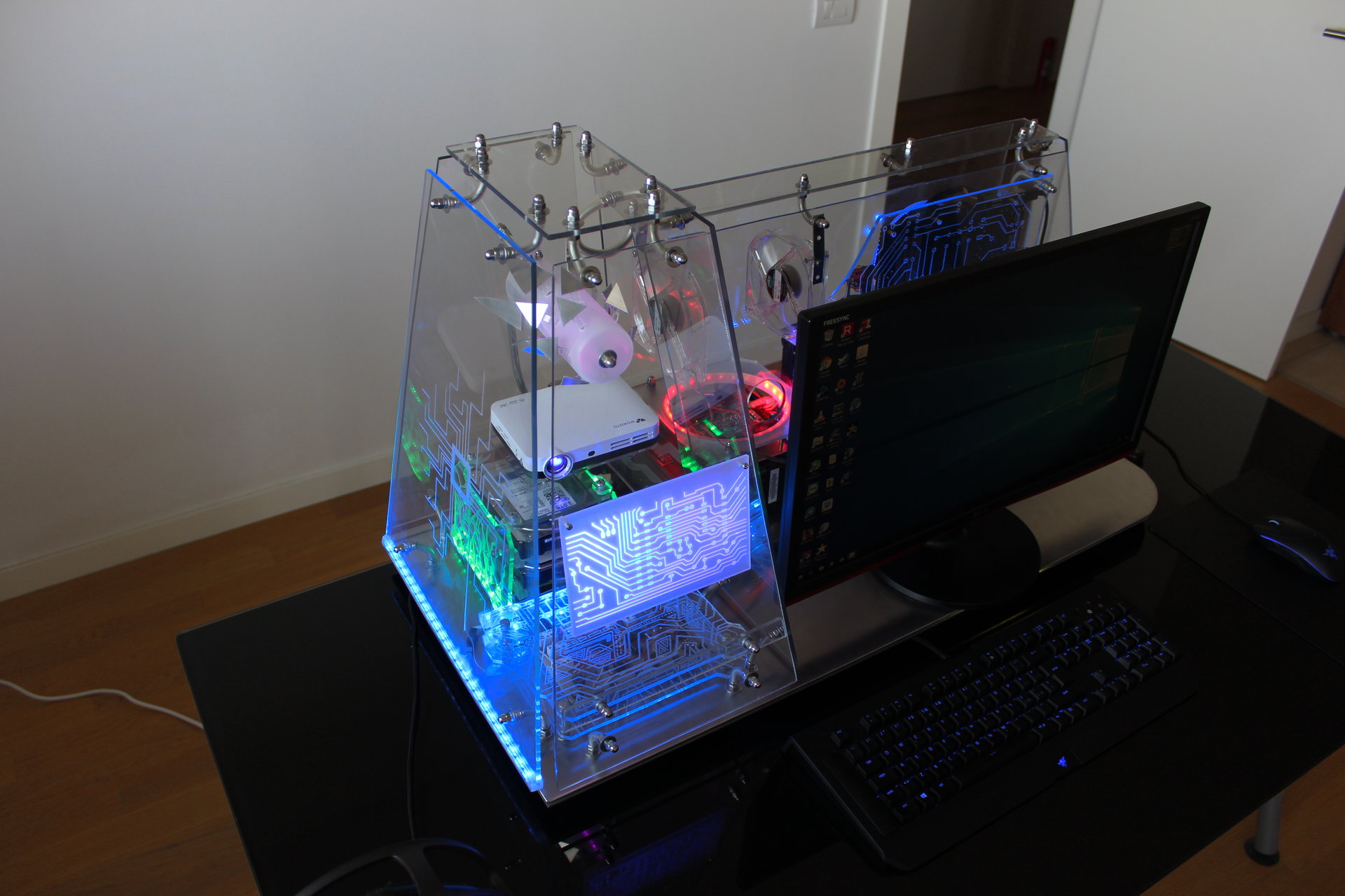
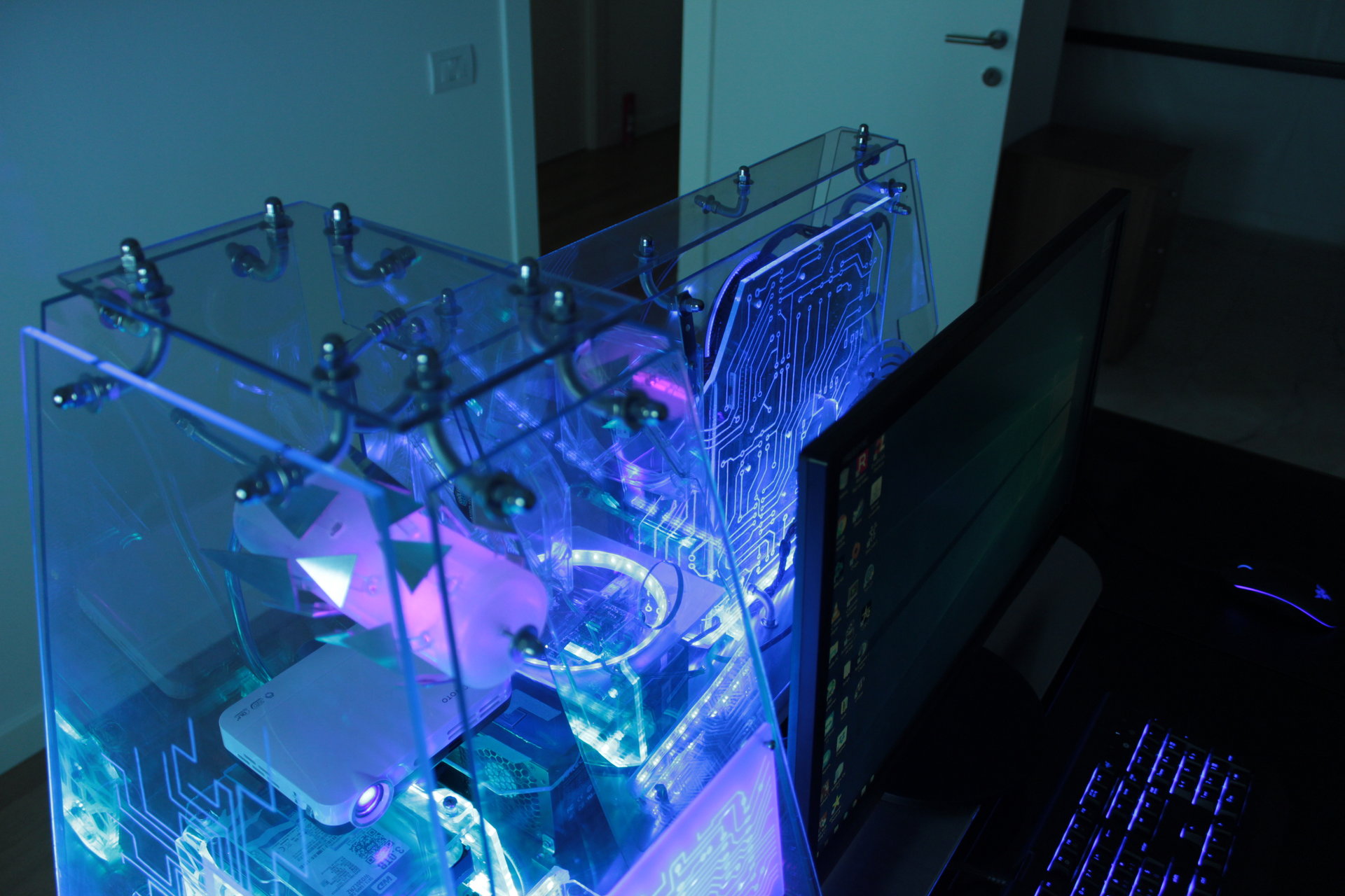
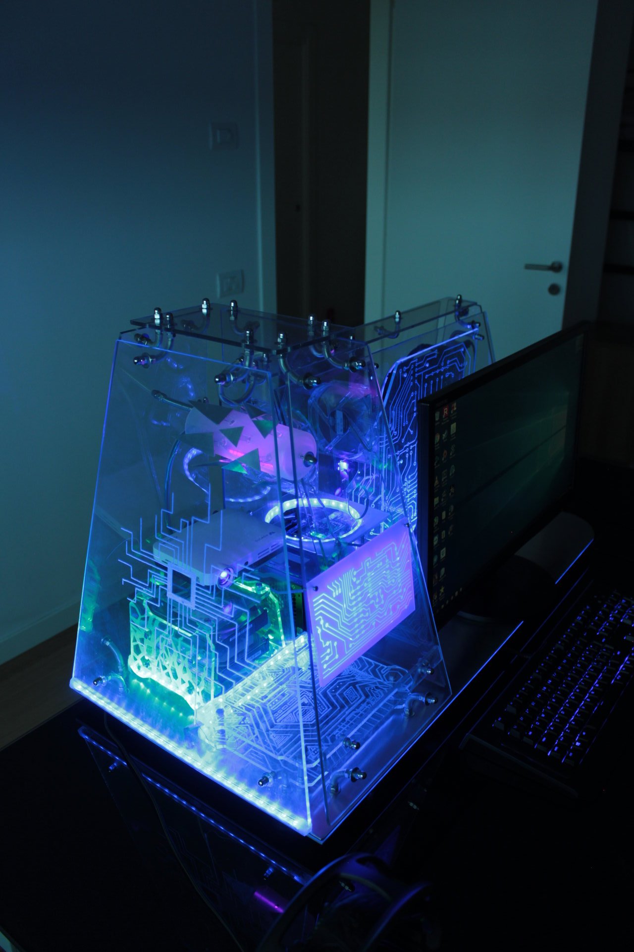
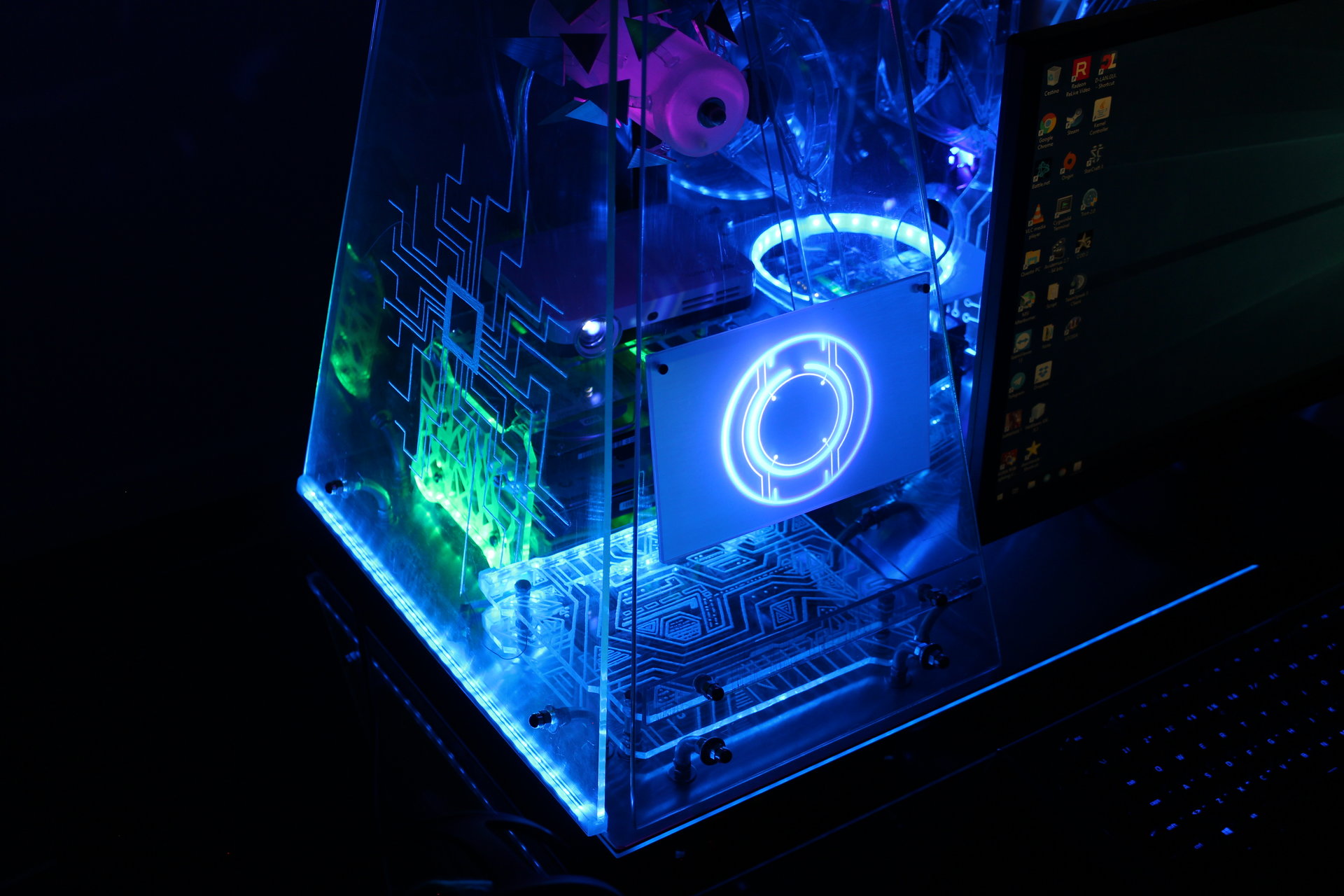
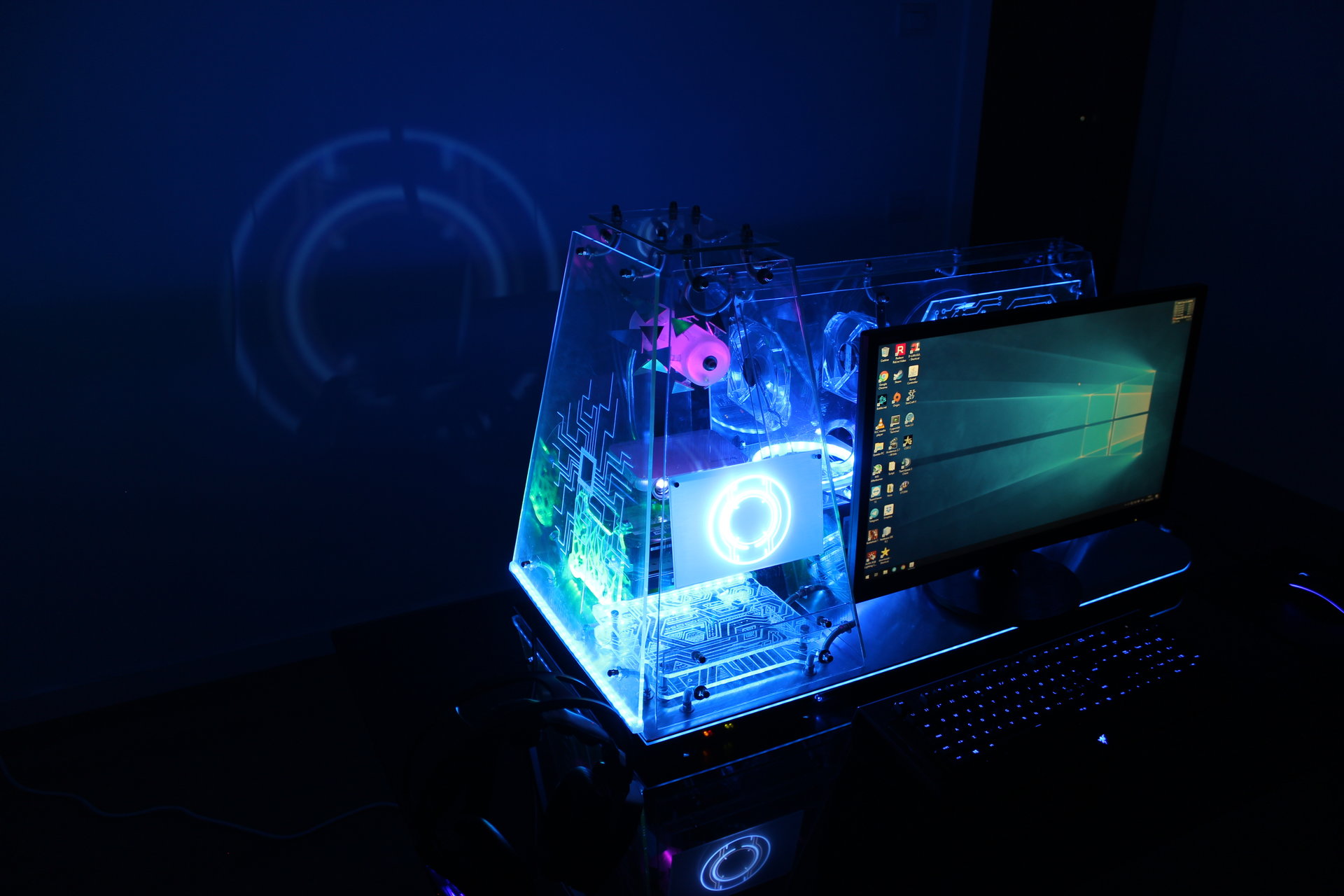
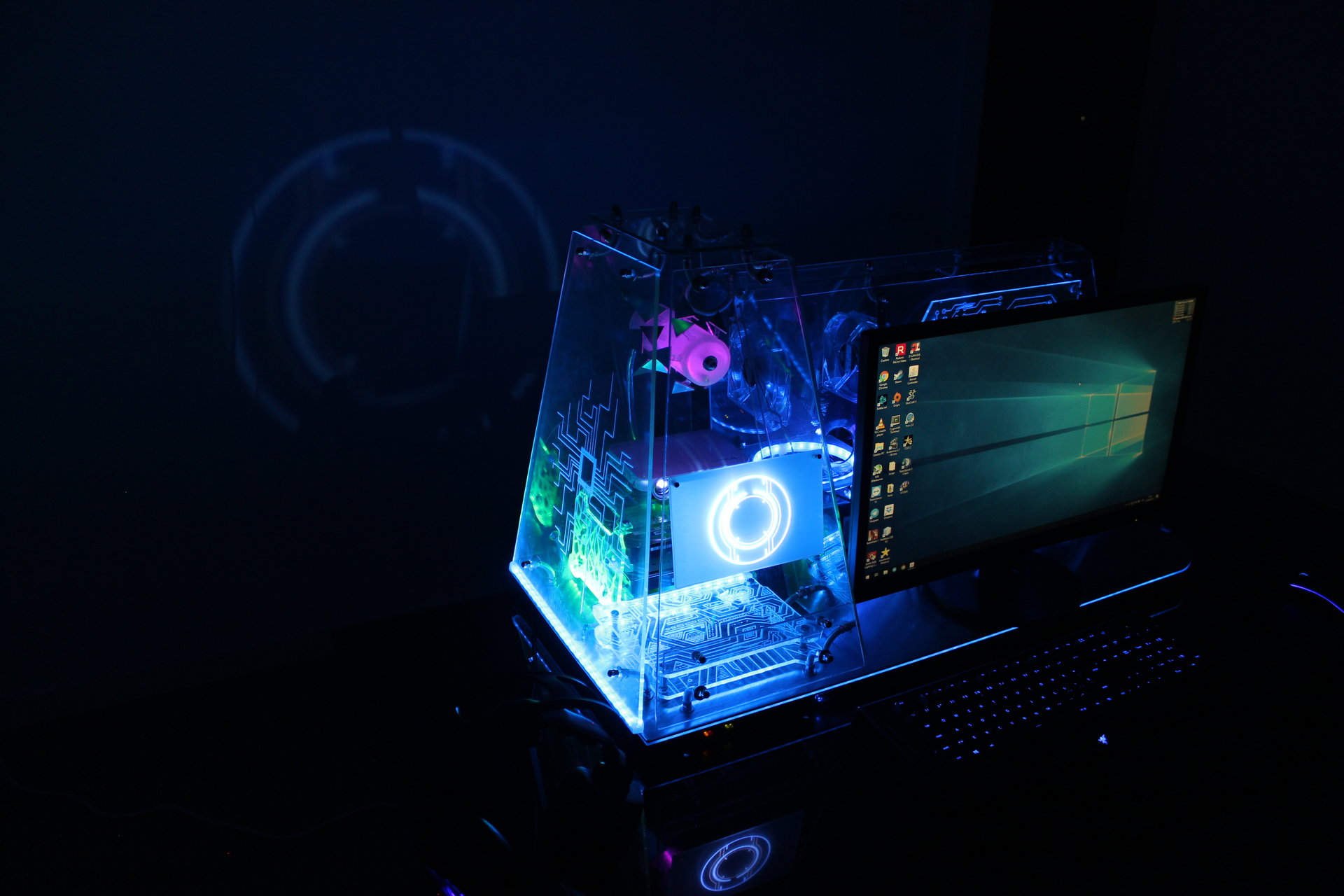
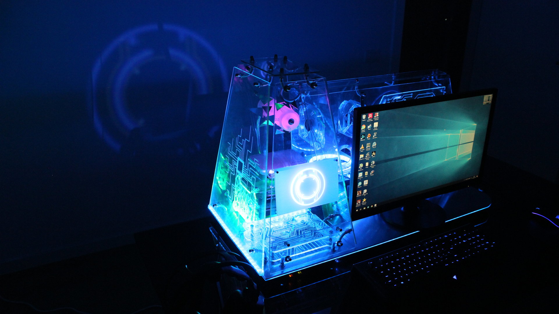
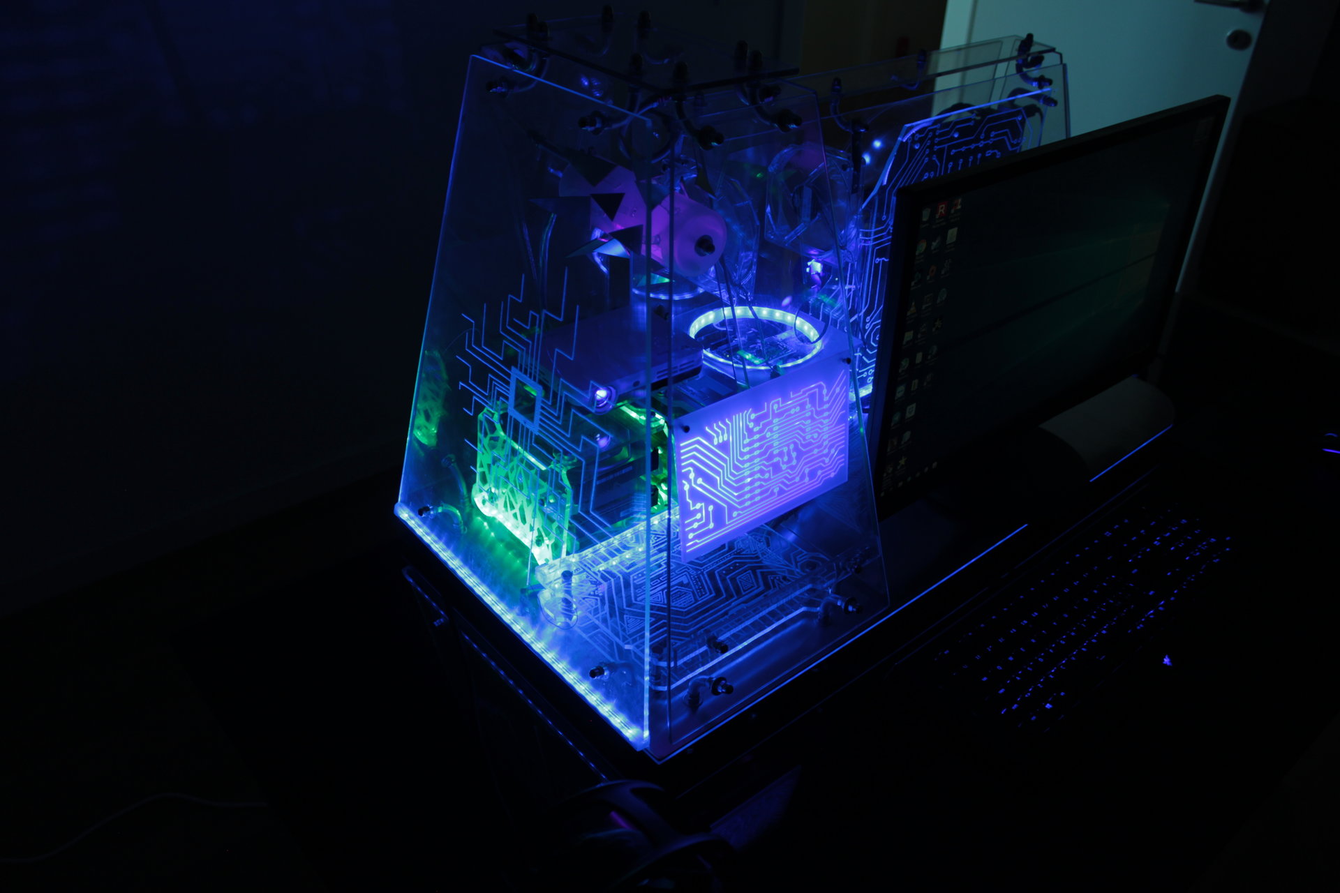
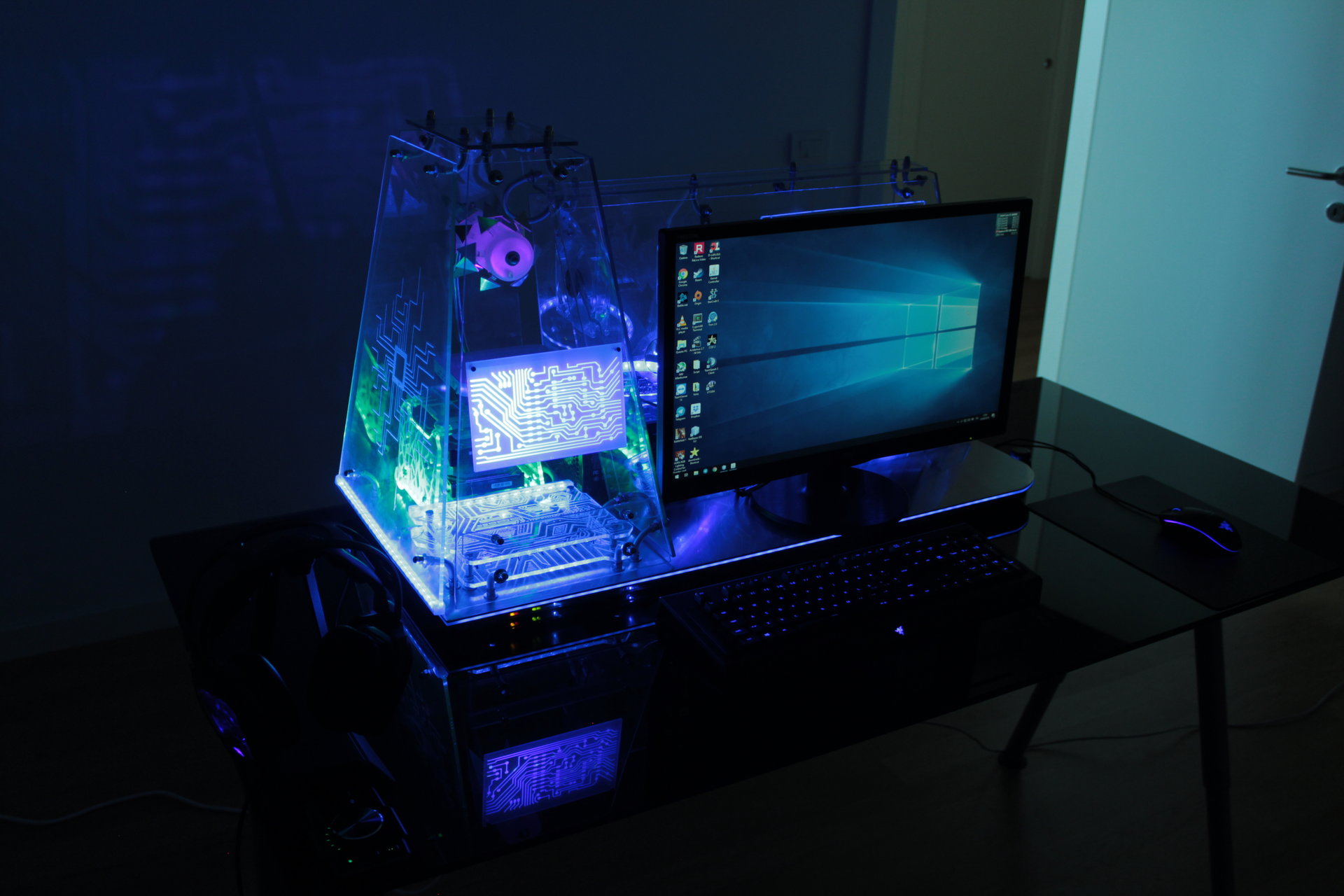
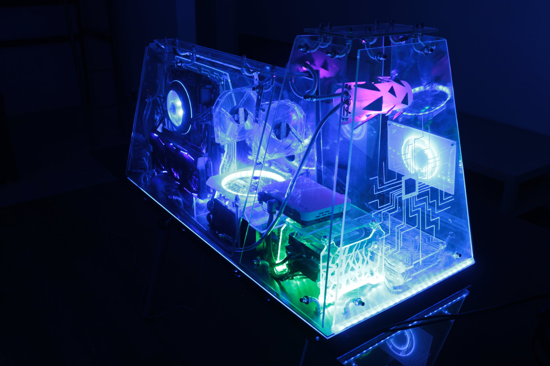
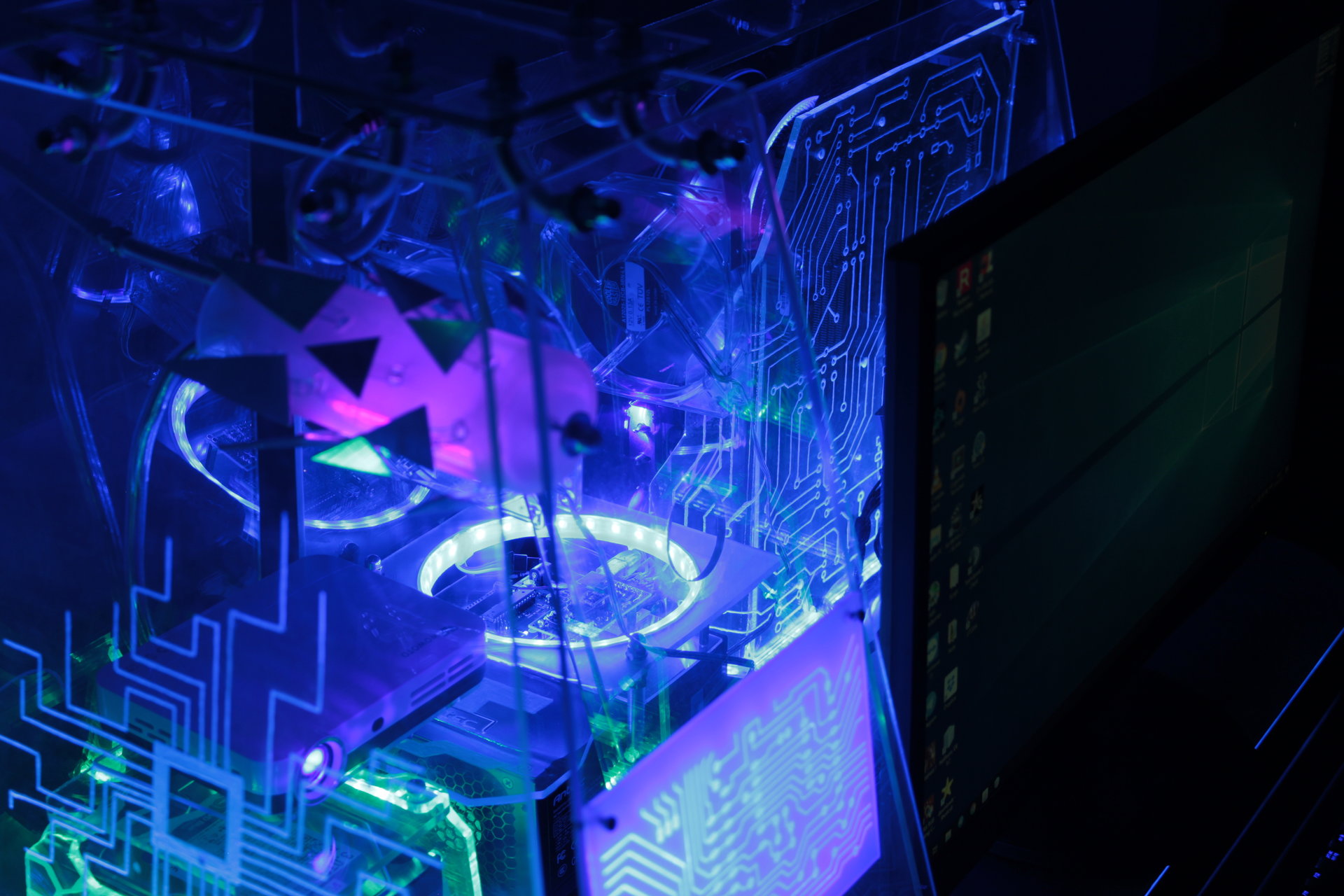
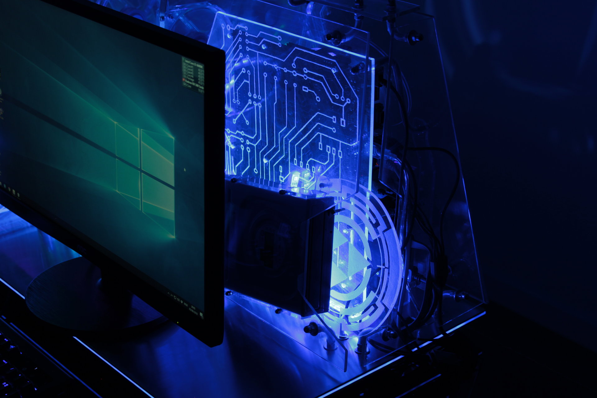
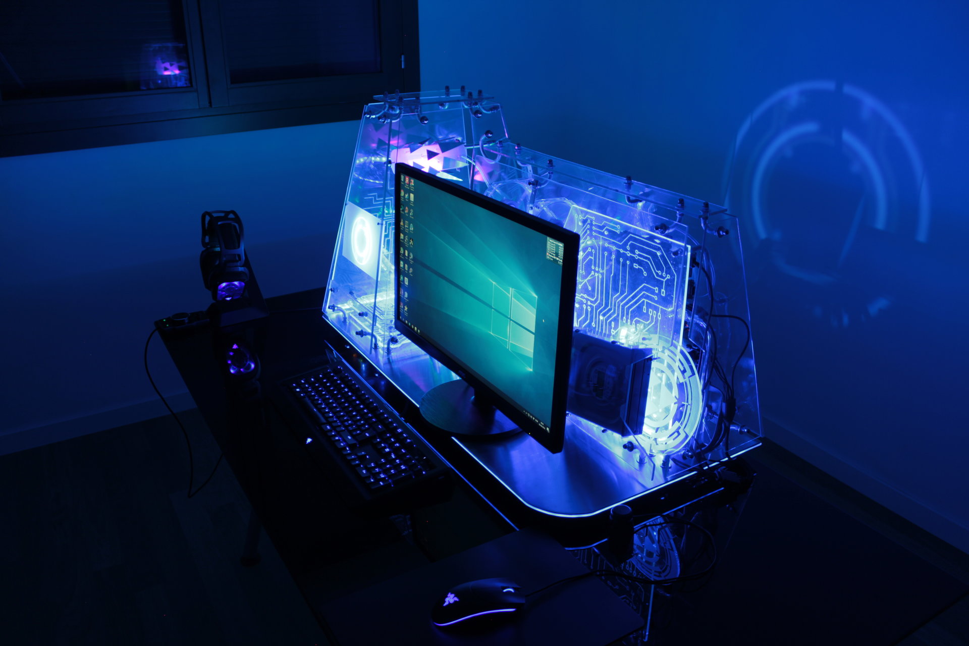
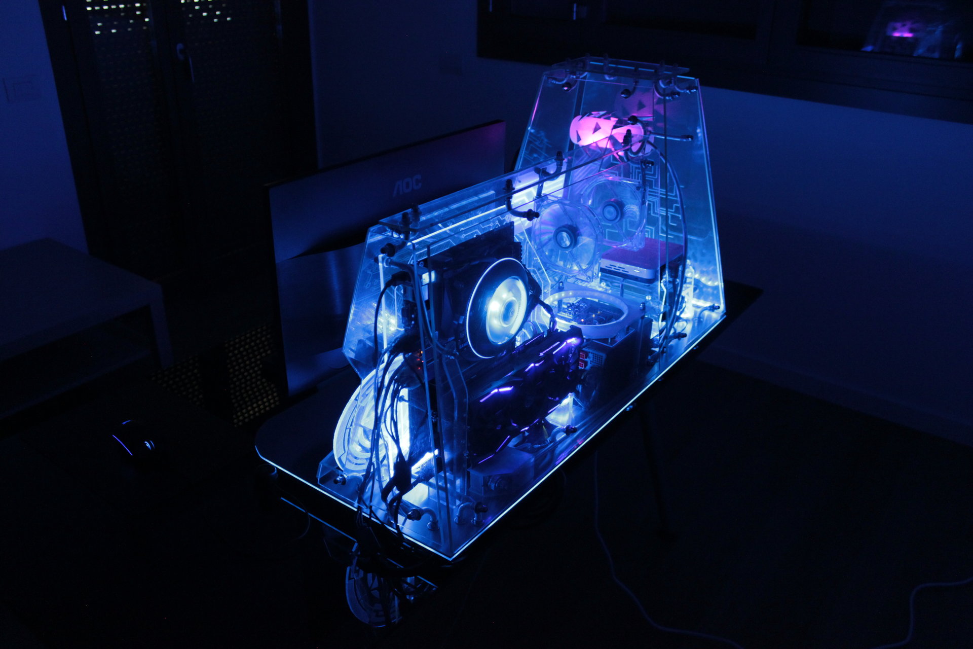
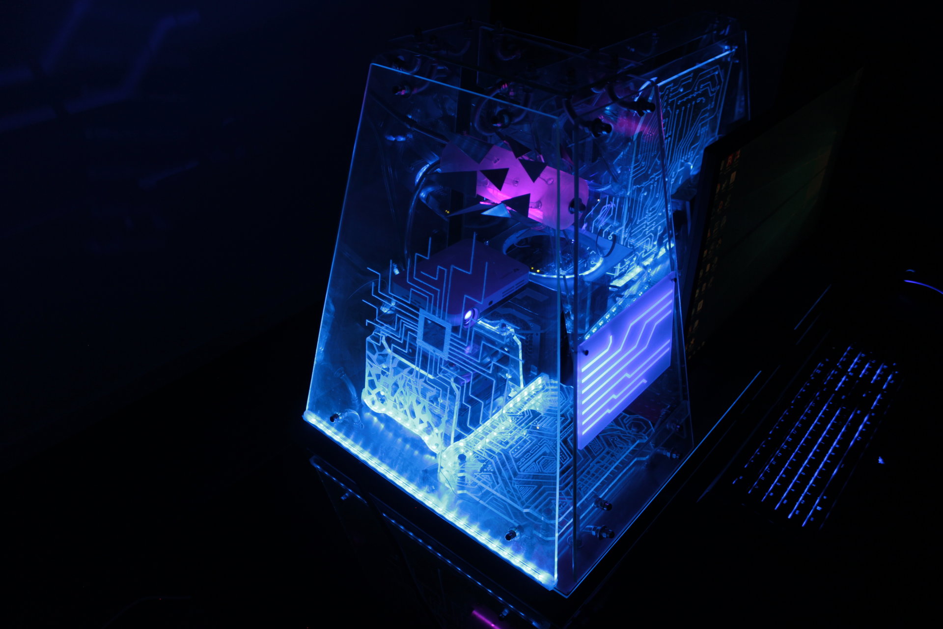
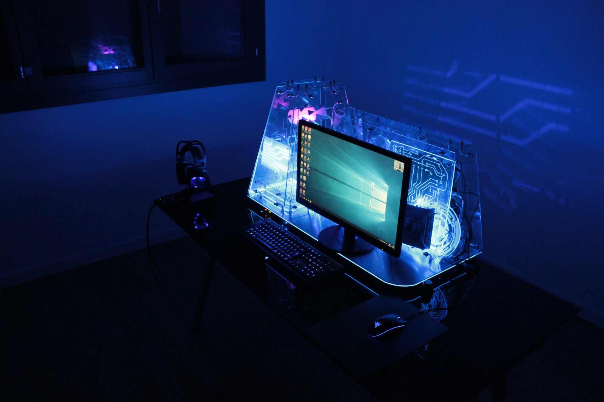
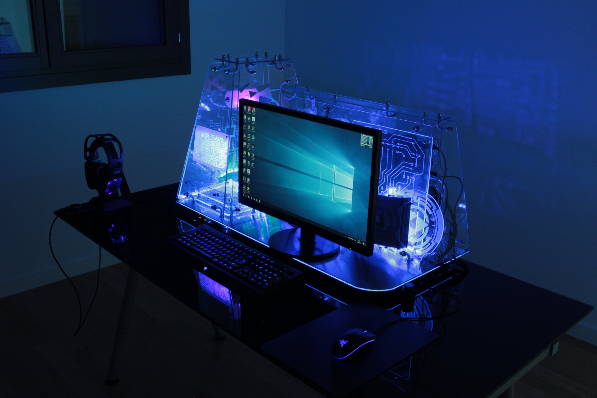
Default state 2:
– mostly blue
– infection effect that fades from blue to green on the hard disks
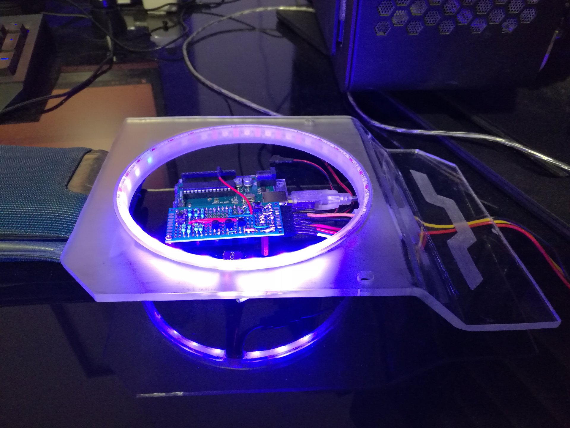
– Pulsating blue Arduino ring
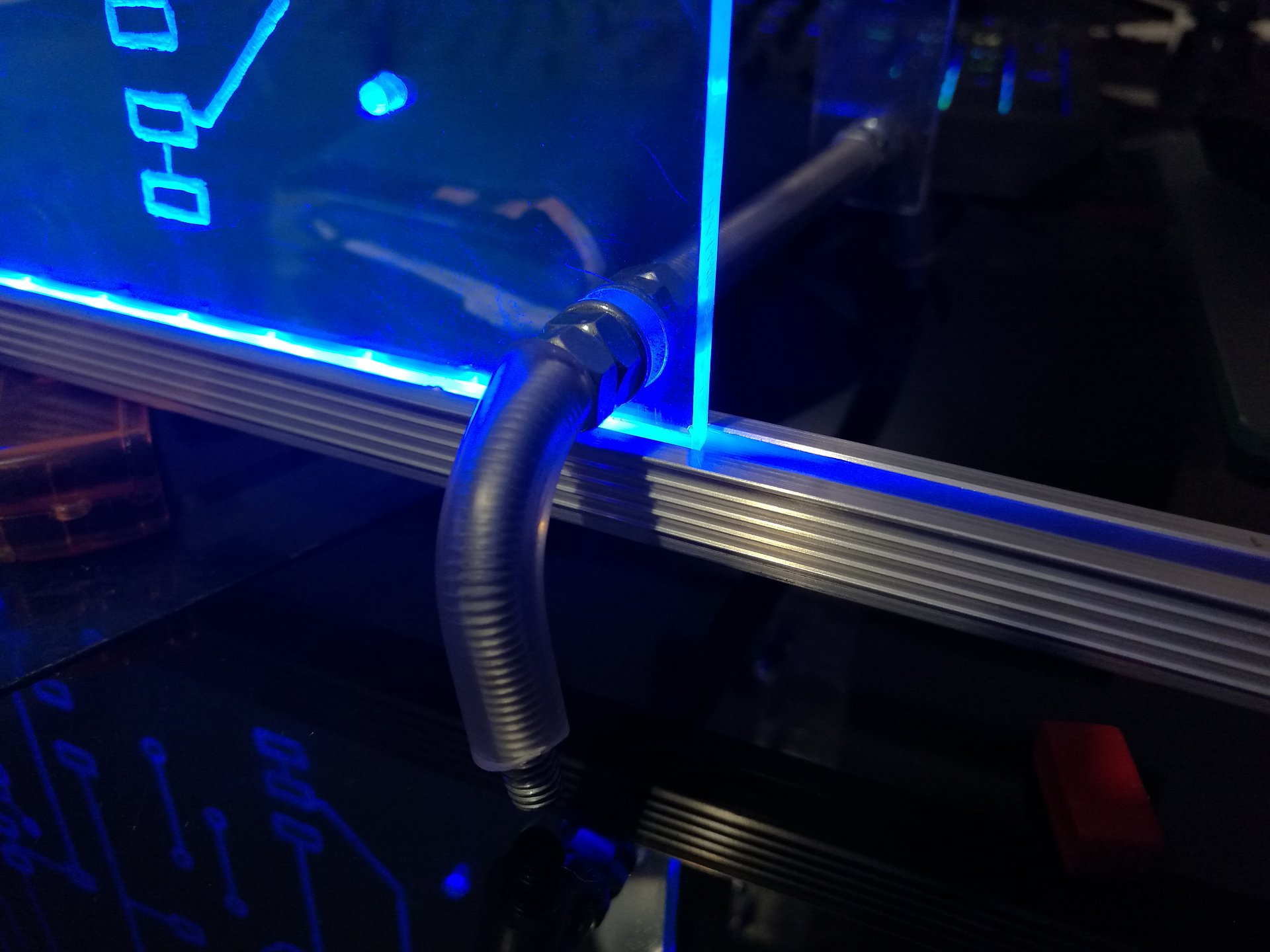
– Blue base perimeter
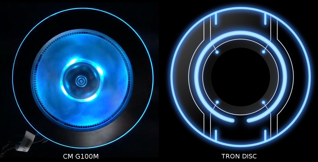
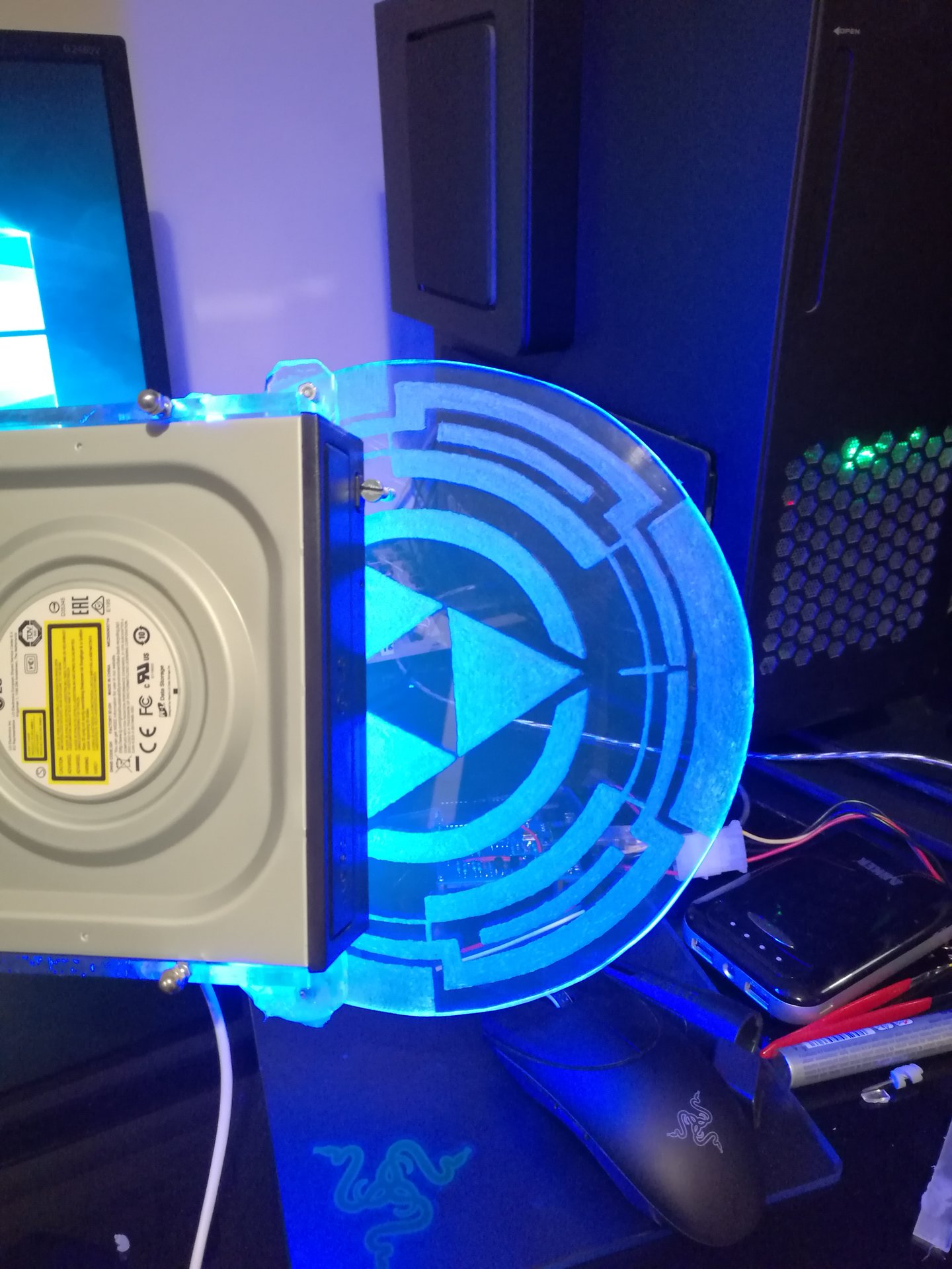
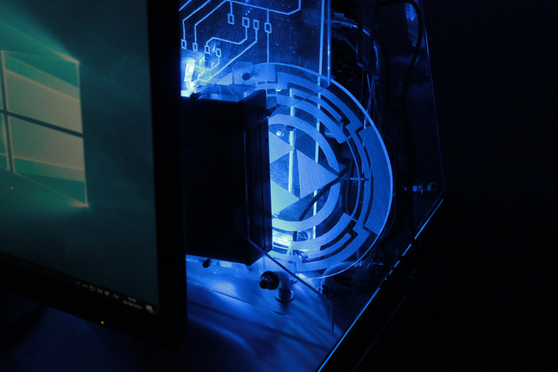
– projector animation: Tron disc
– proximity sensor “charging” effect: blue->green->yellow->red
In this state I like the reflection of the projected Tron disc on the room’s wall behind the case (and the disc is animated, in the video it can be seen in movement).
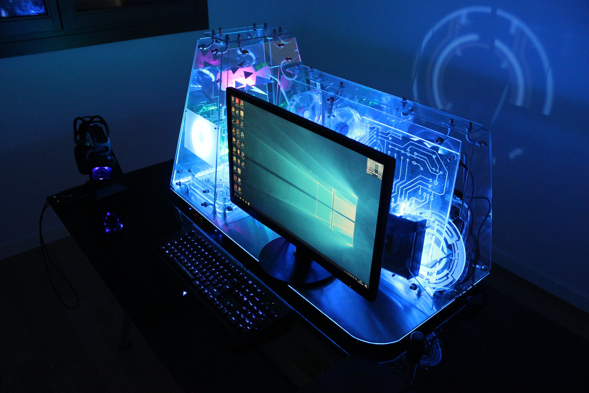

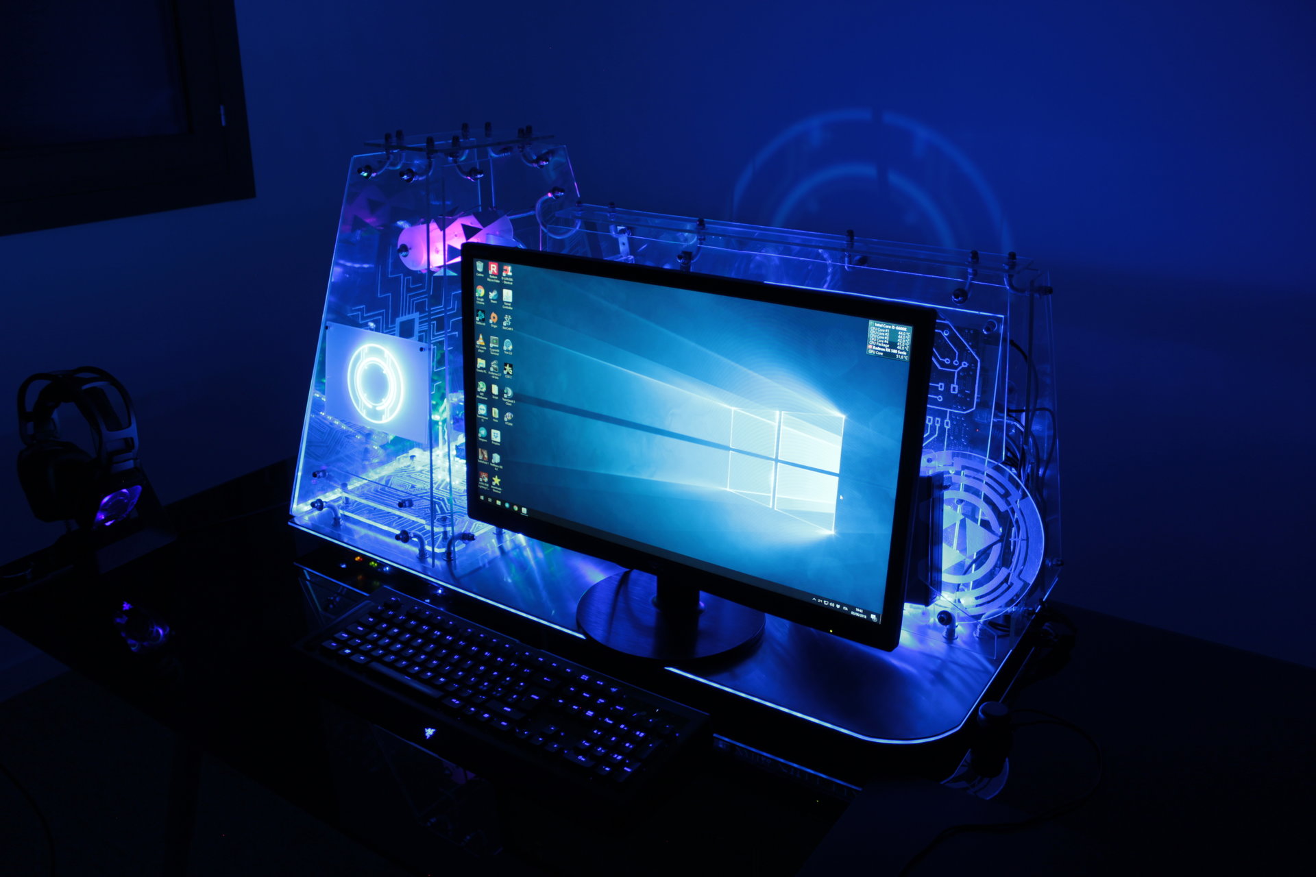
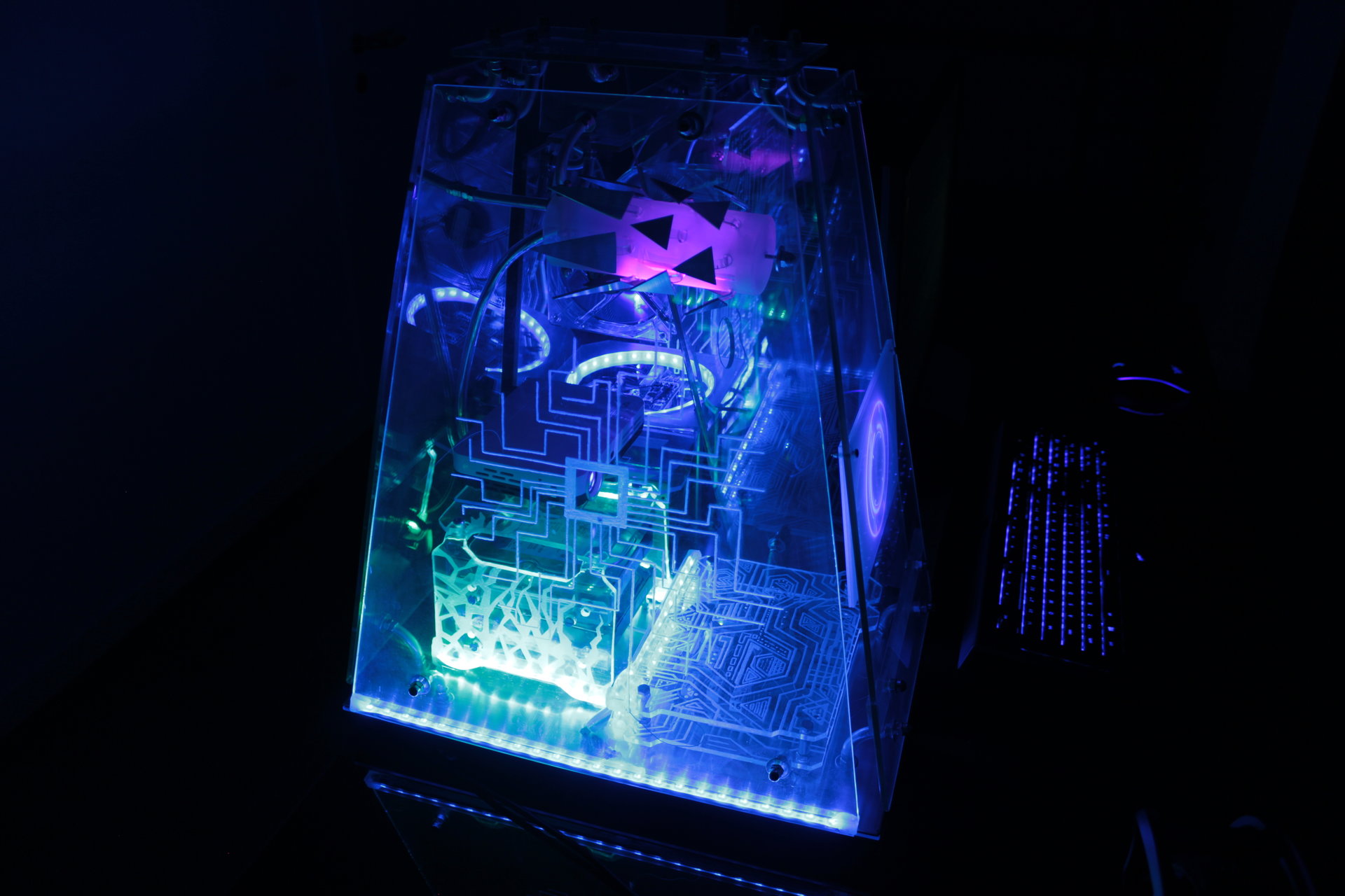

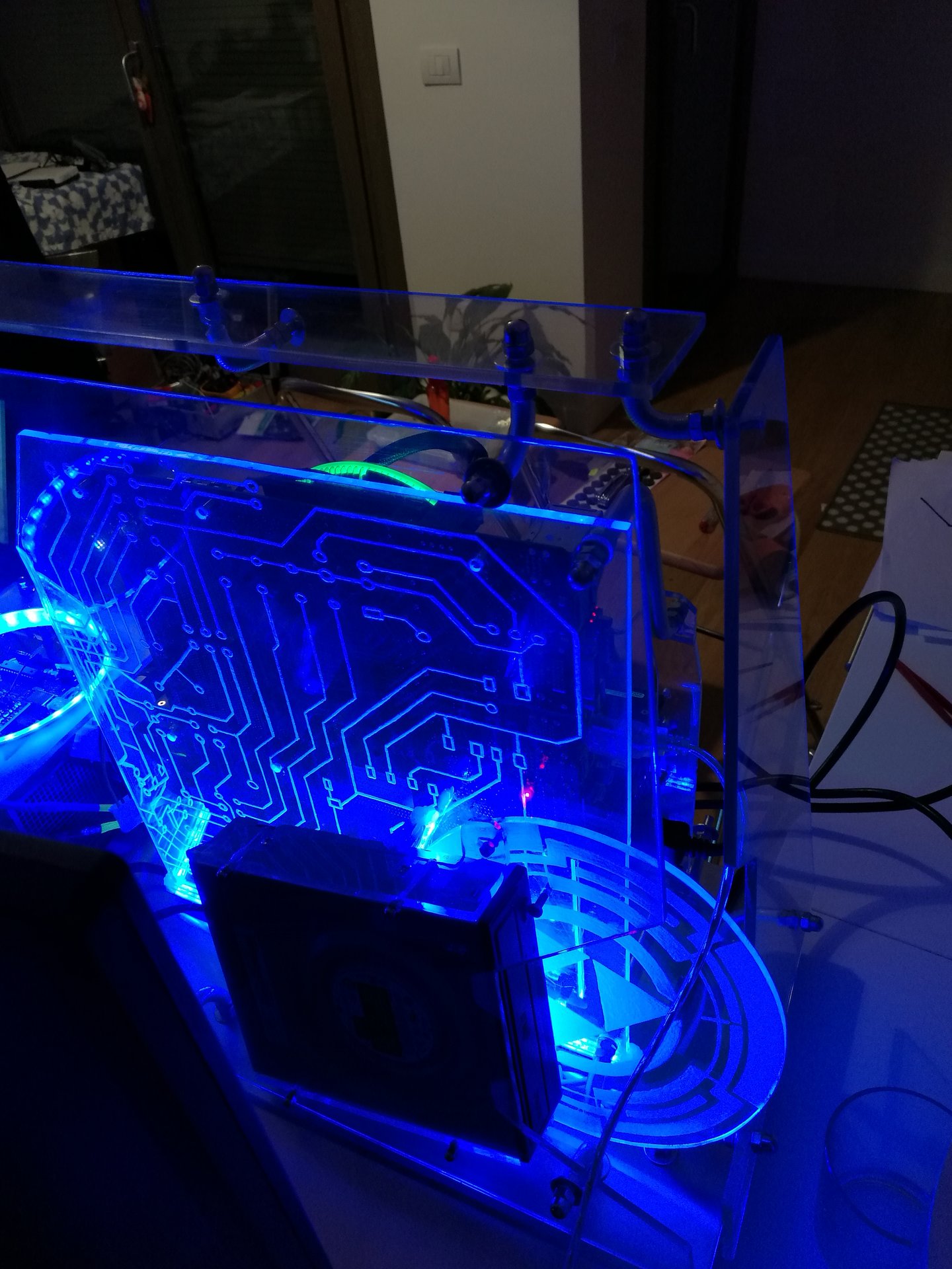
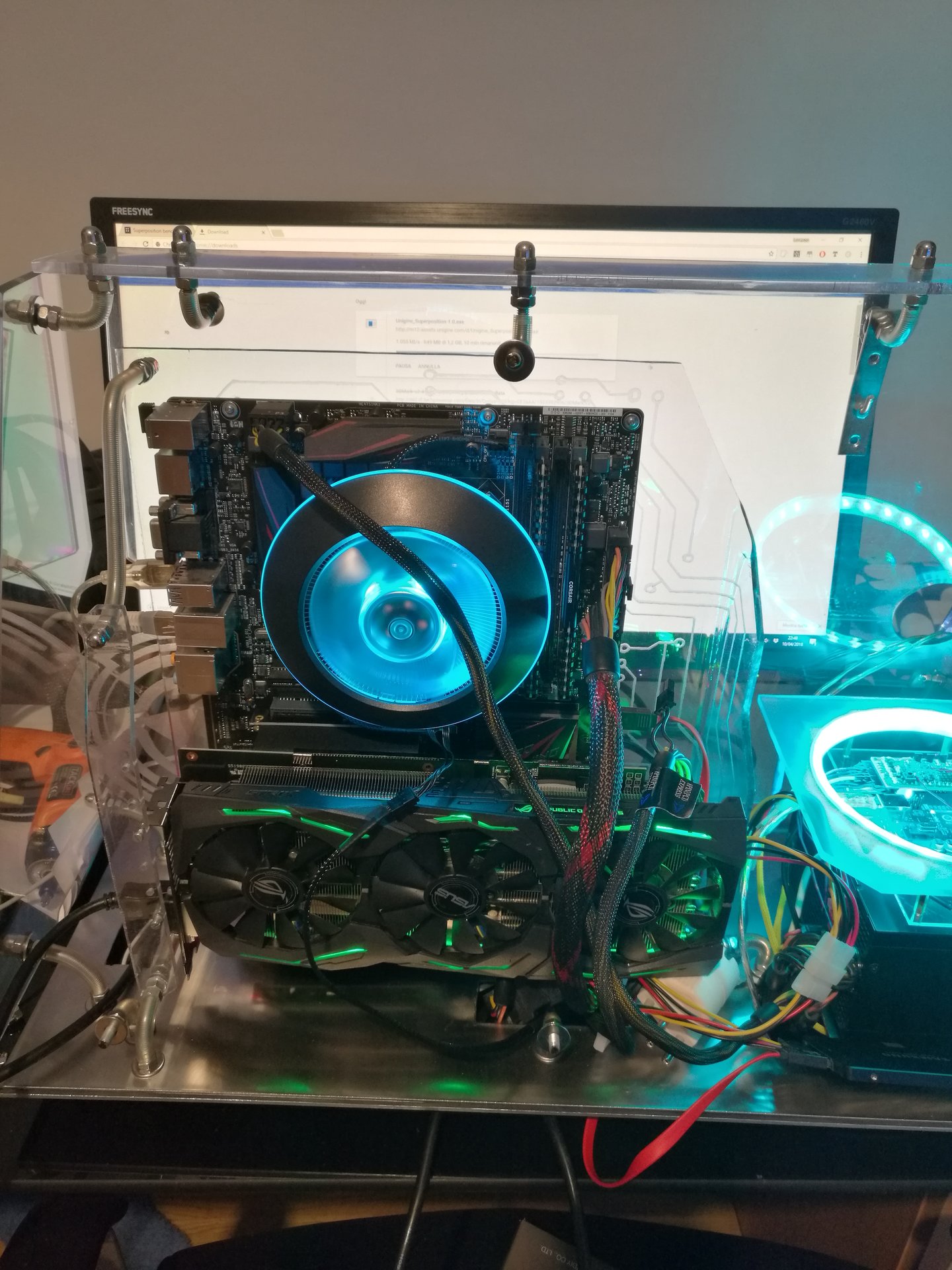
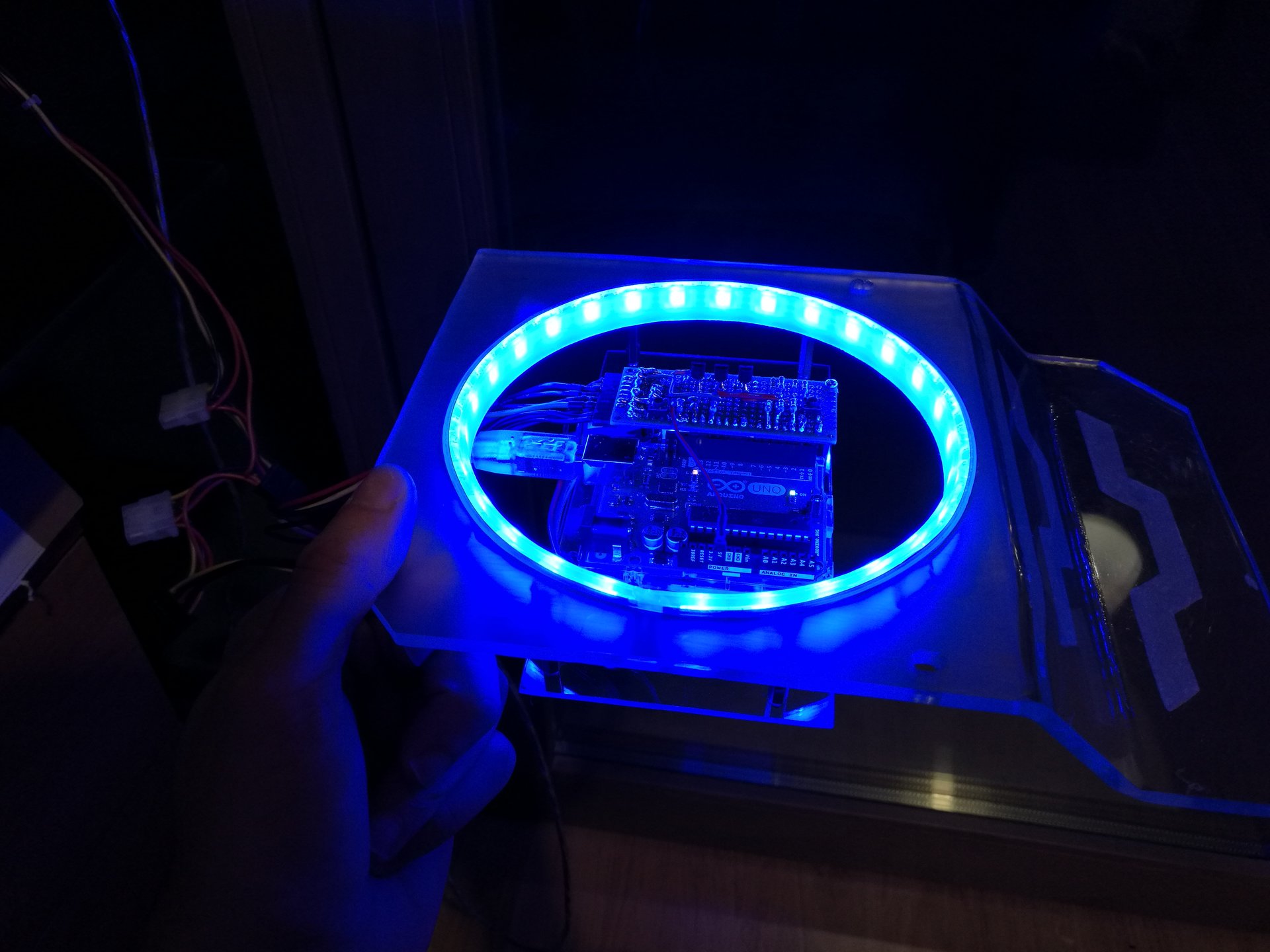
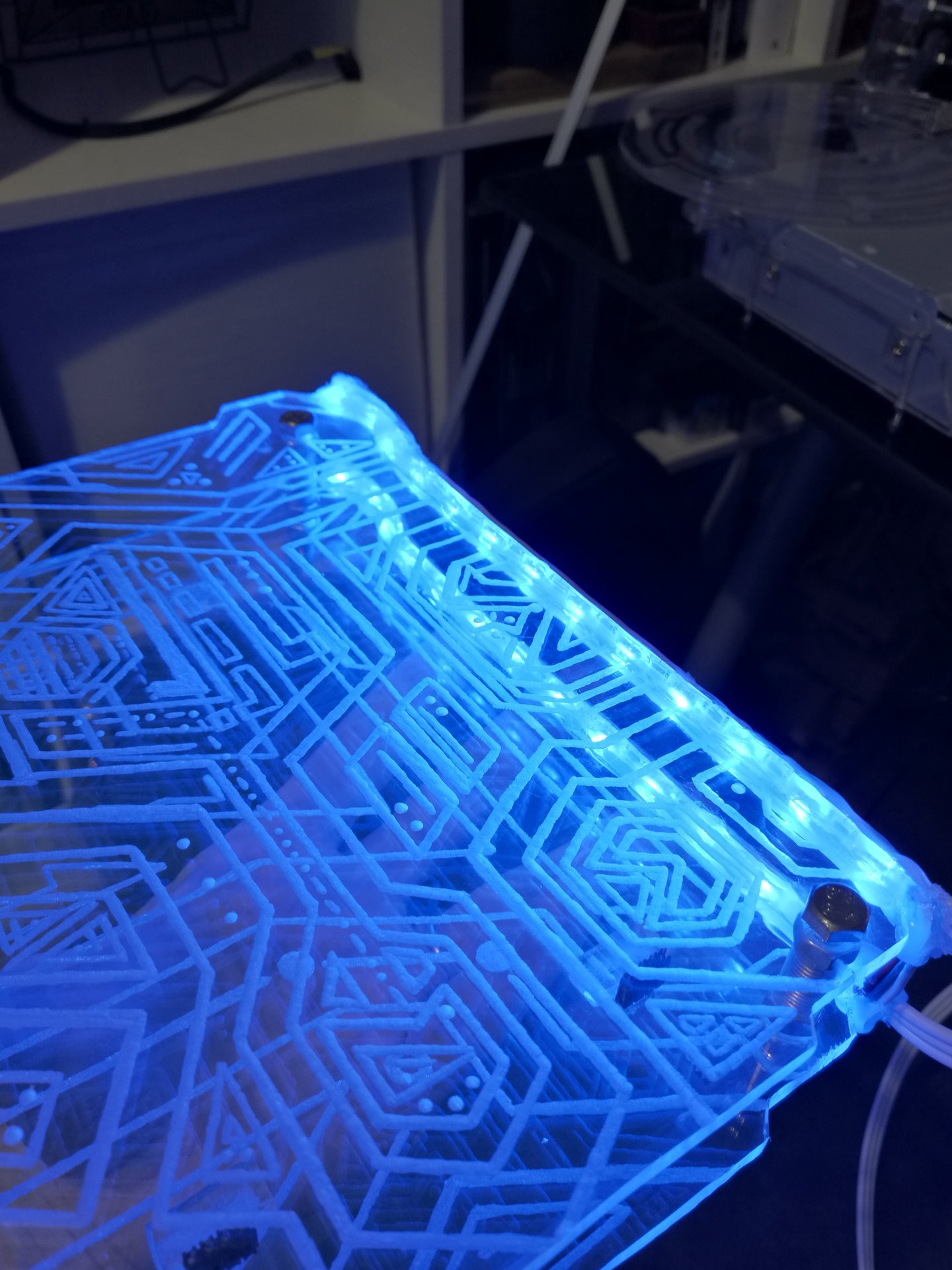
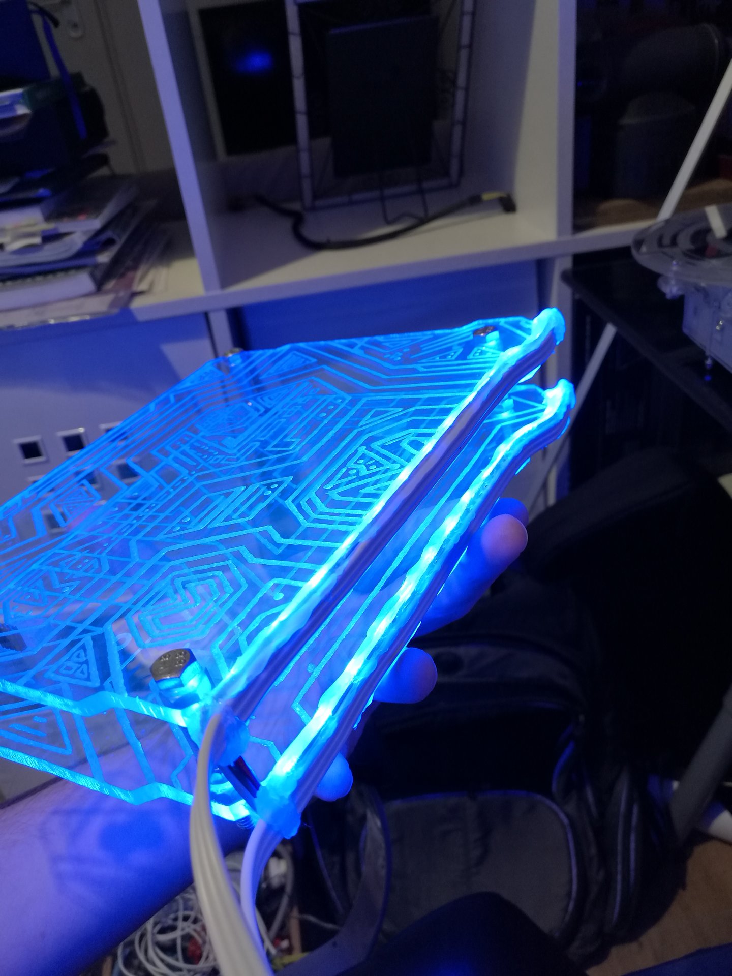
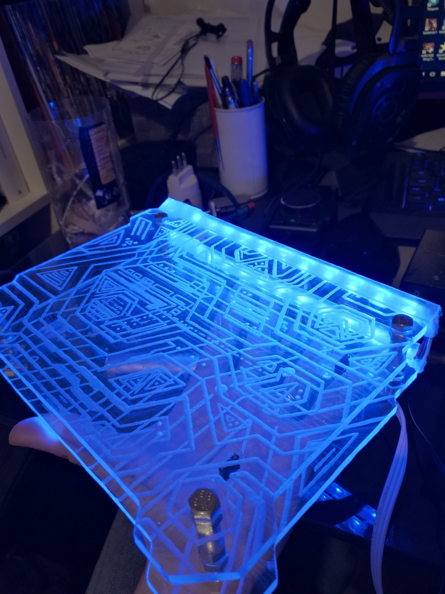
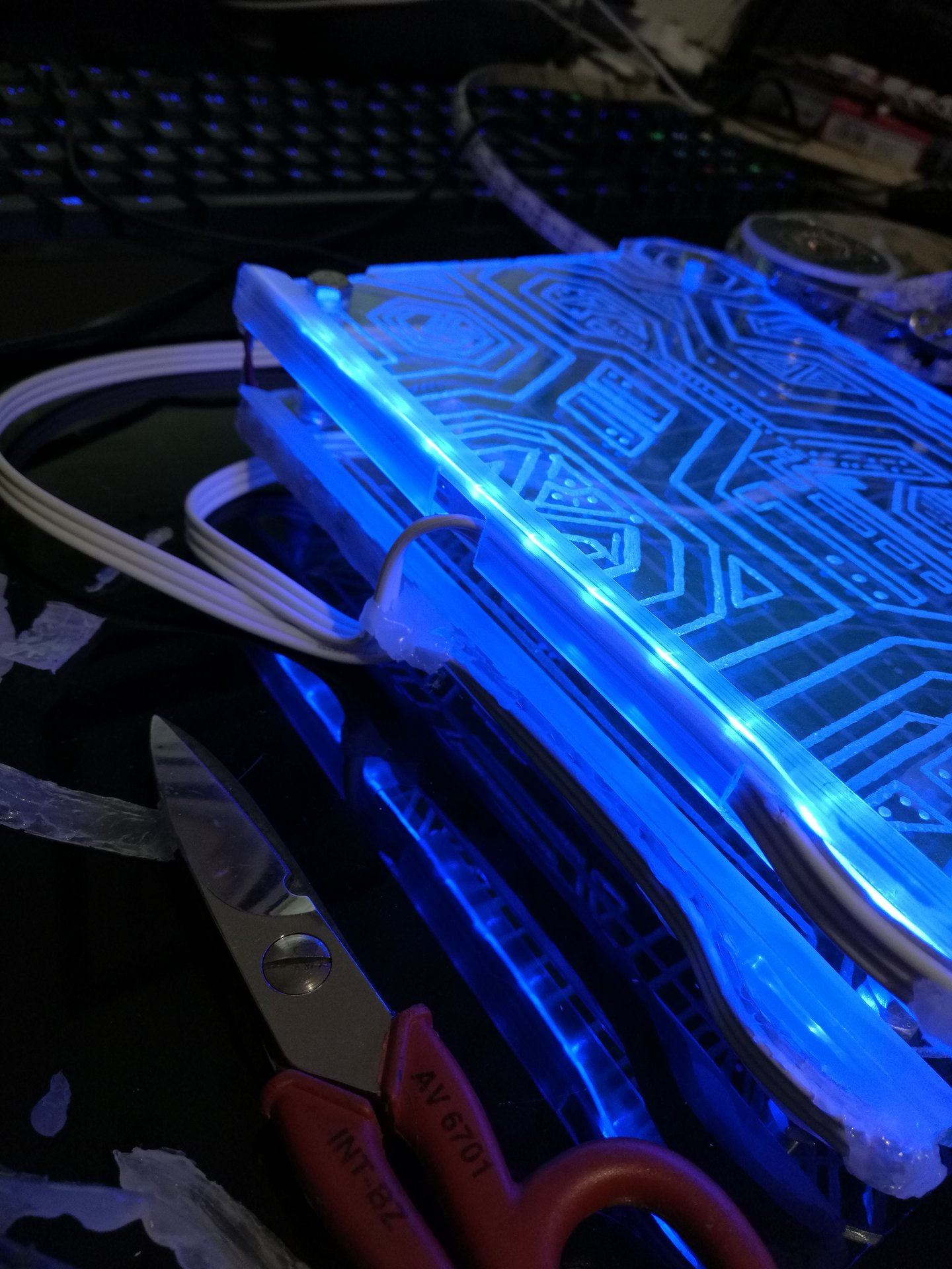
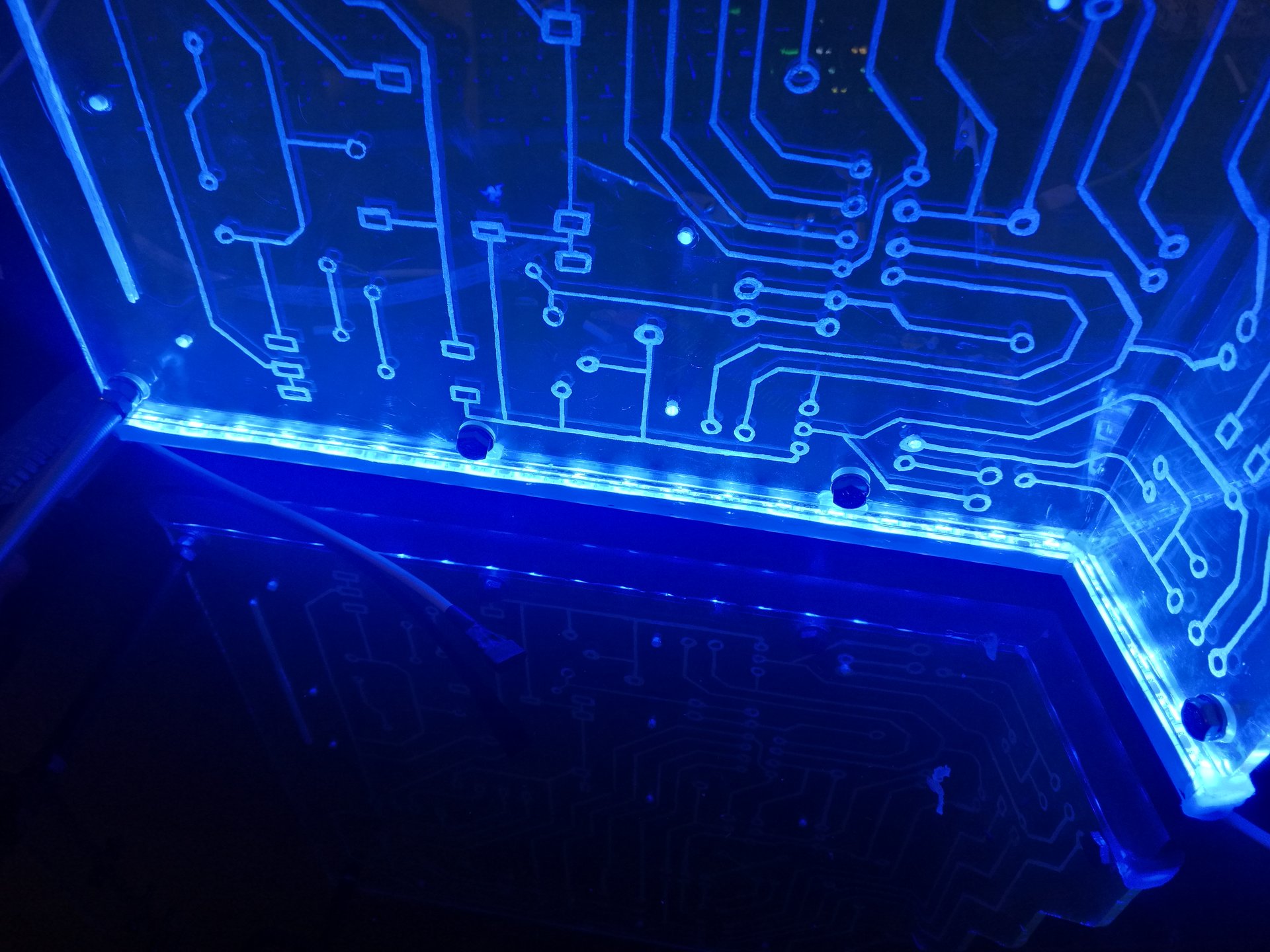
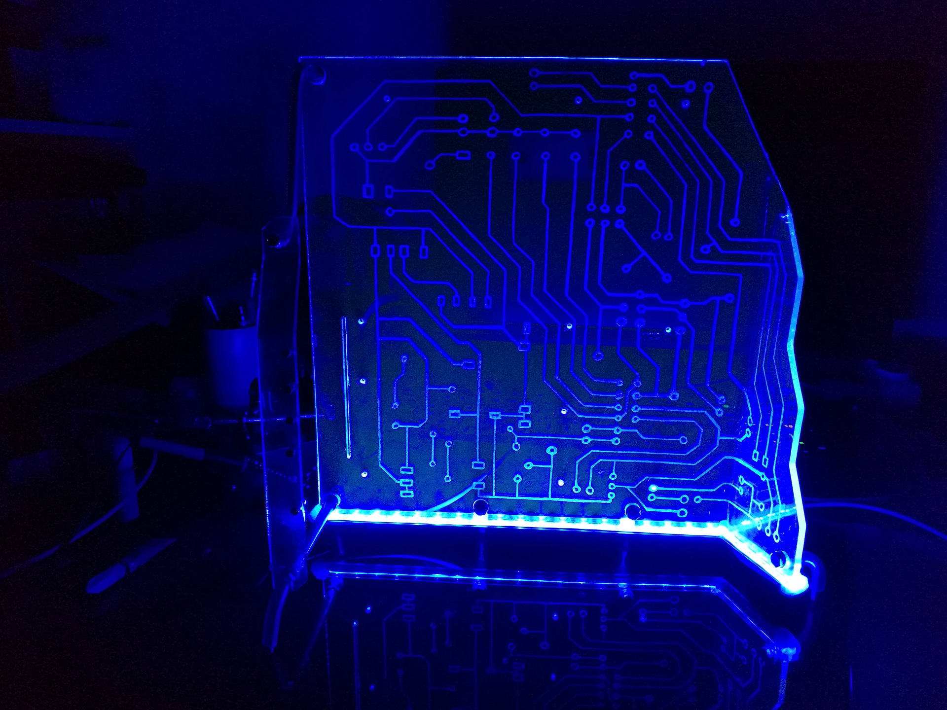
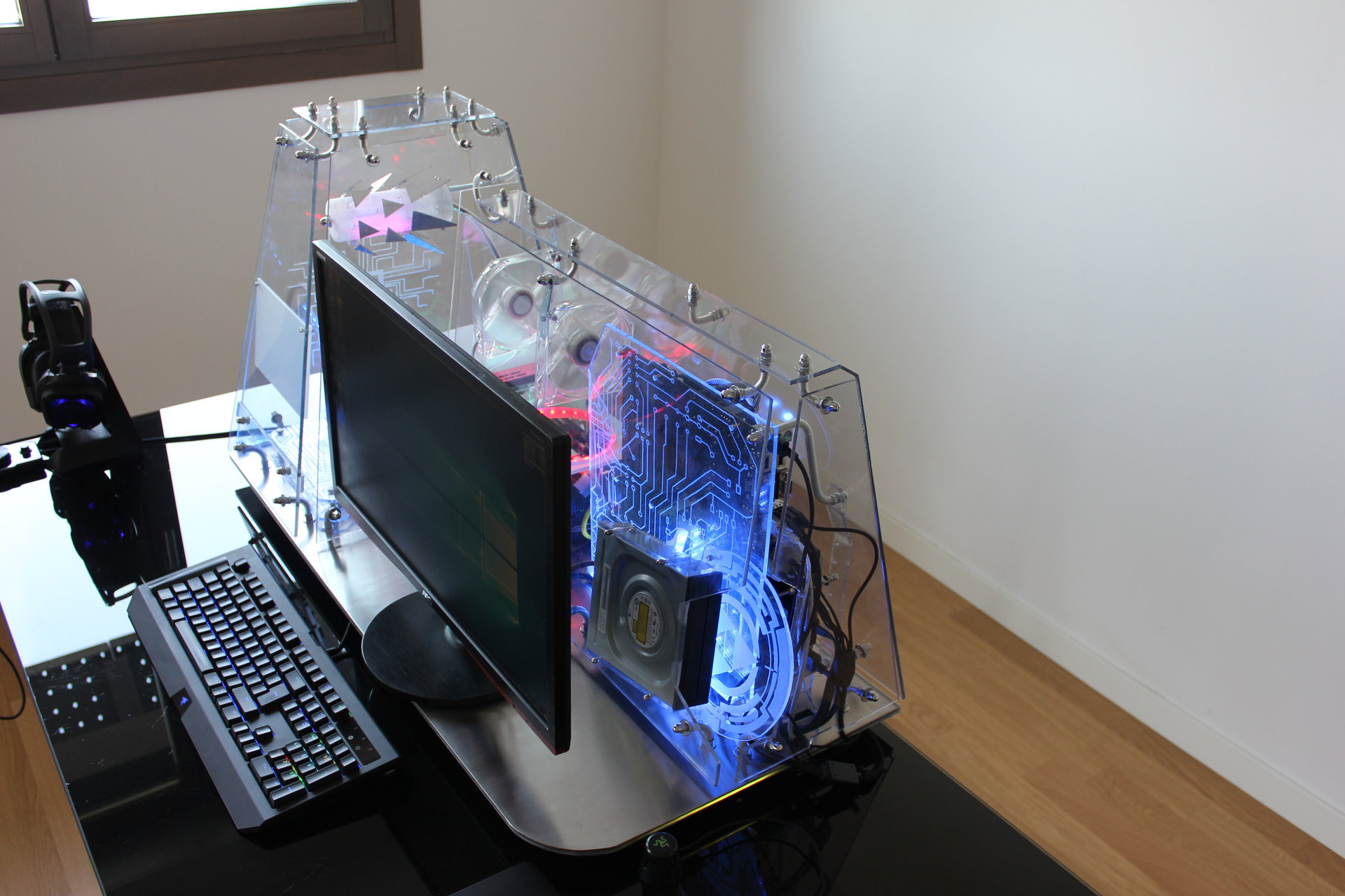
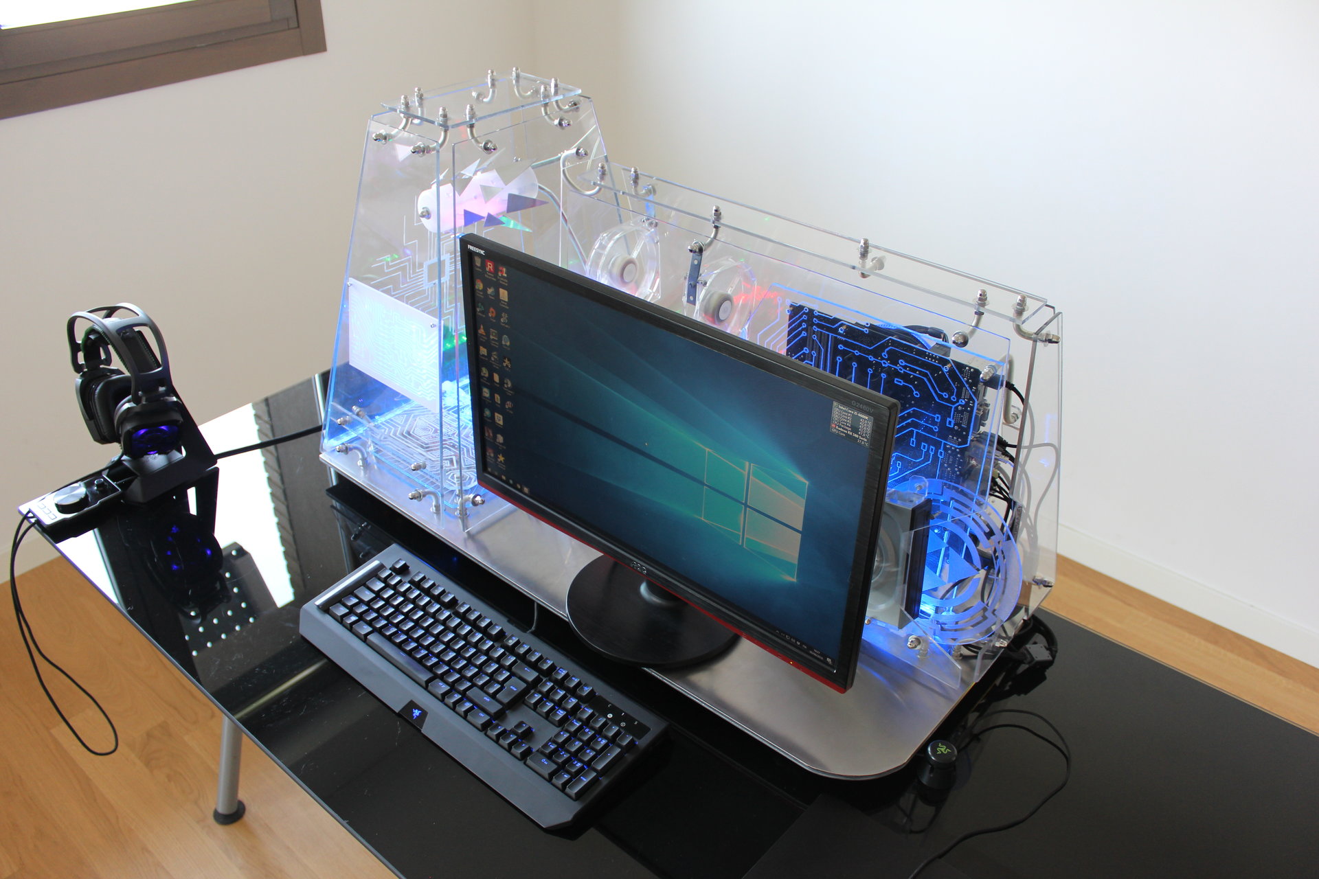
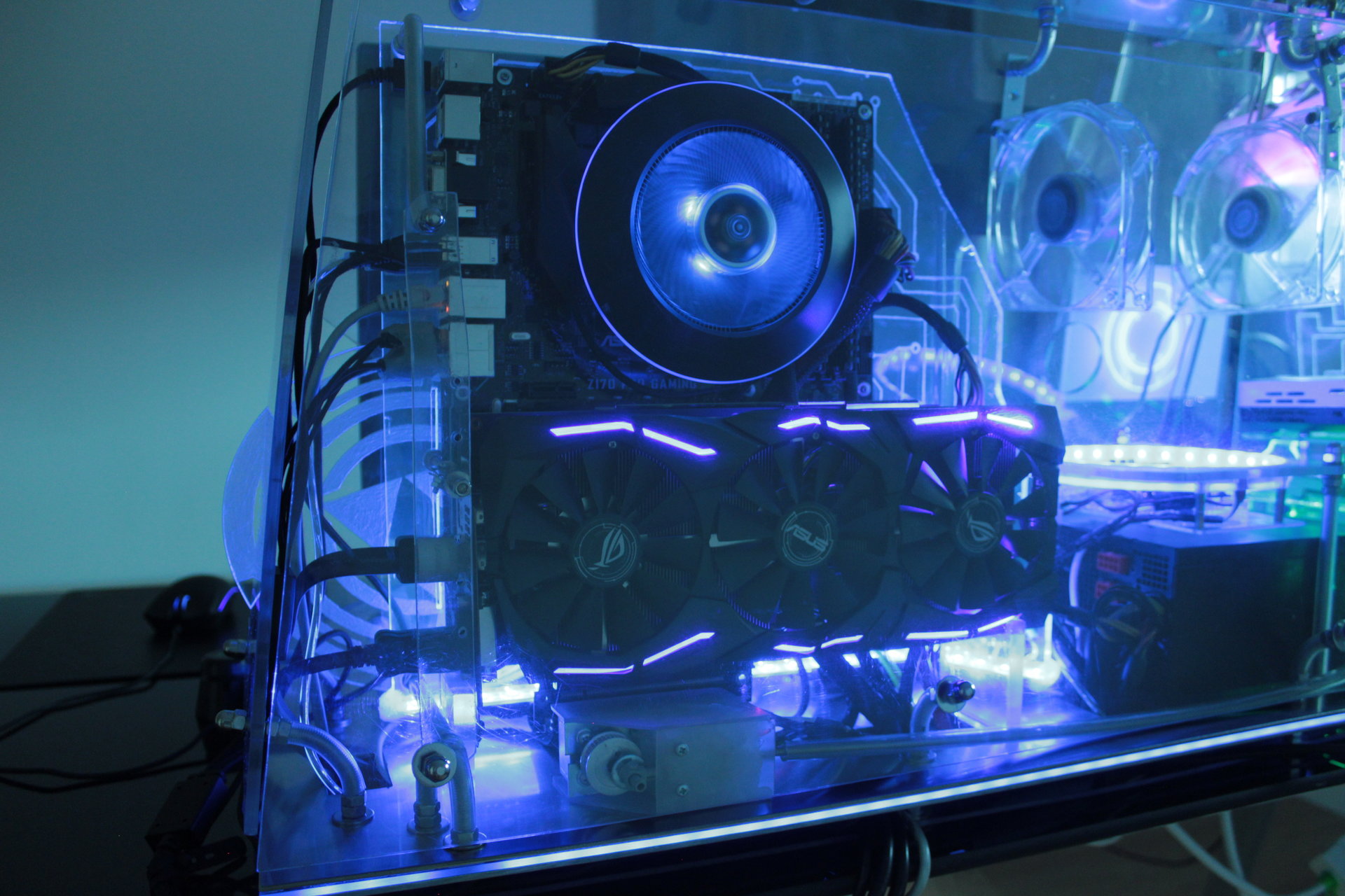
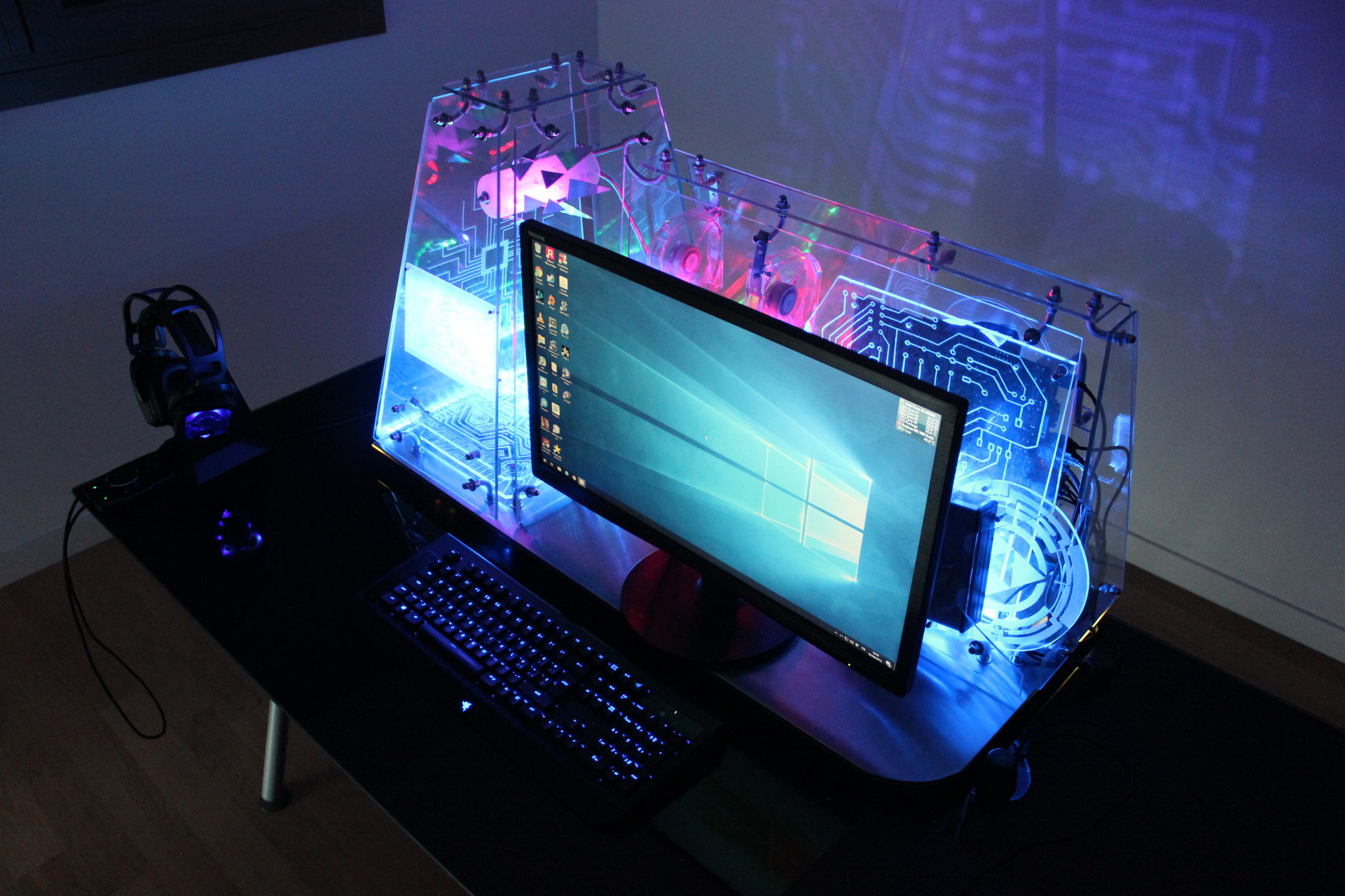
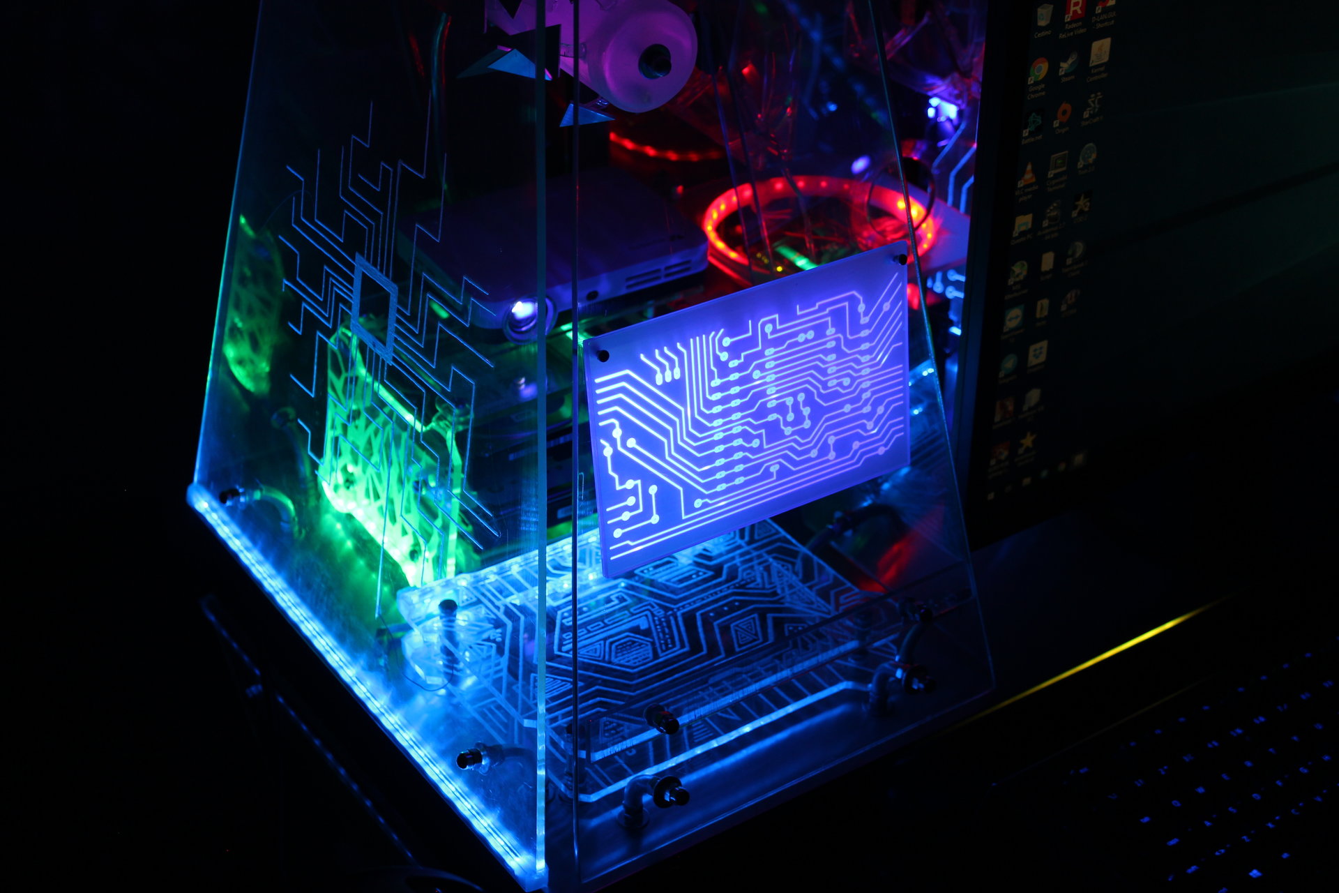
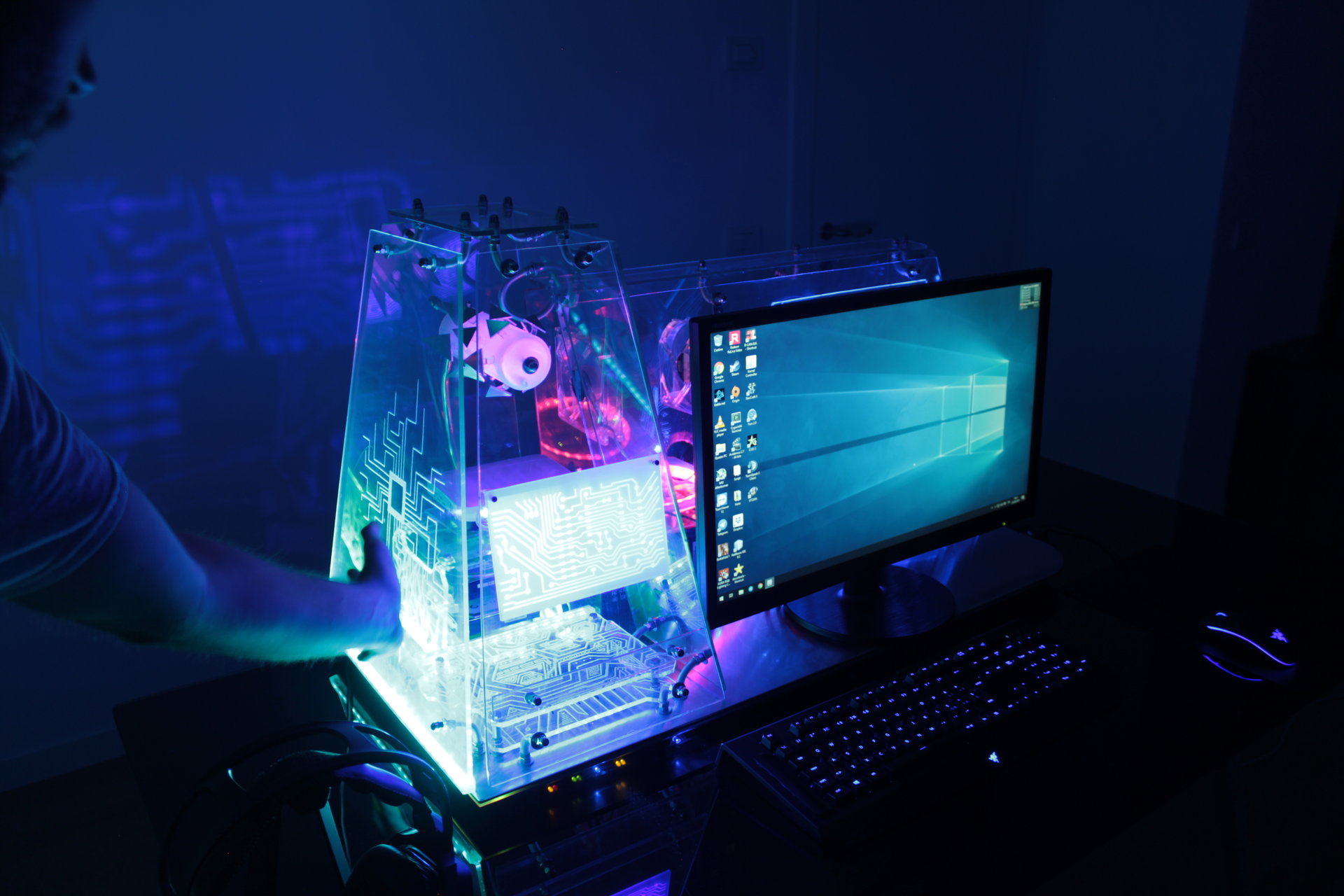
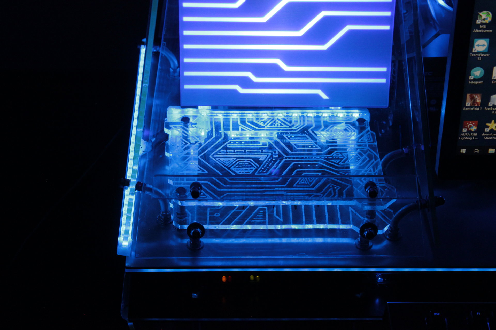
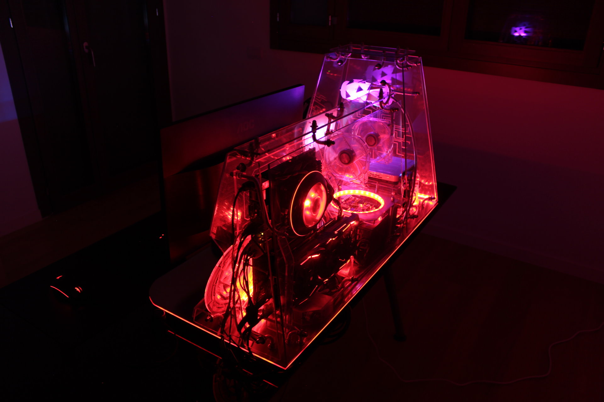
Blue state:
– all blue
– projector animation: Tron themed lines
– proximity sensor “charging” effect: blue->green->yellow->red

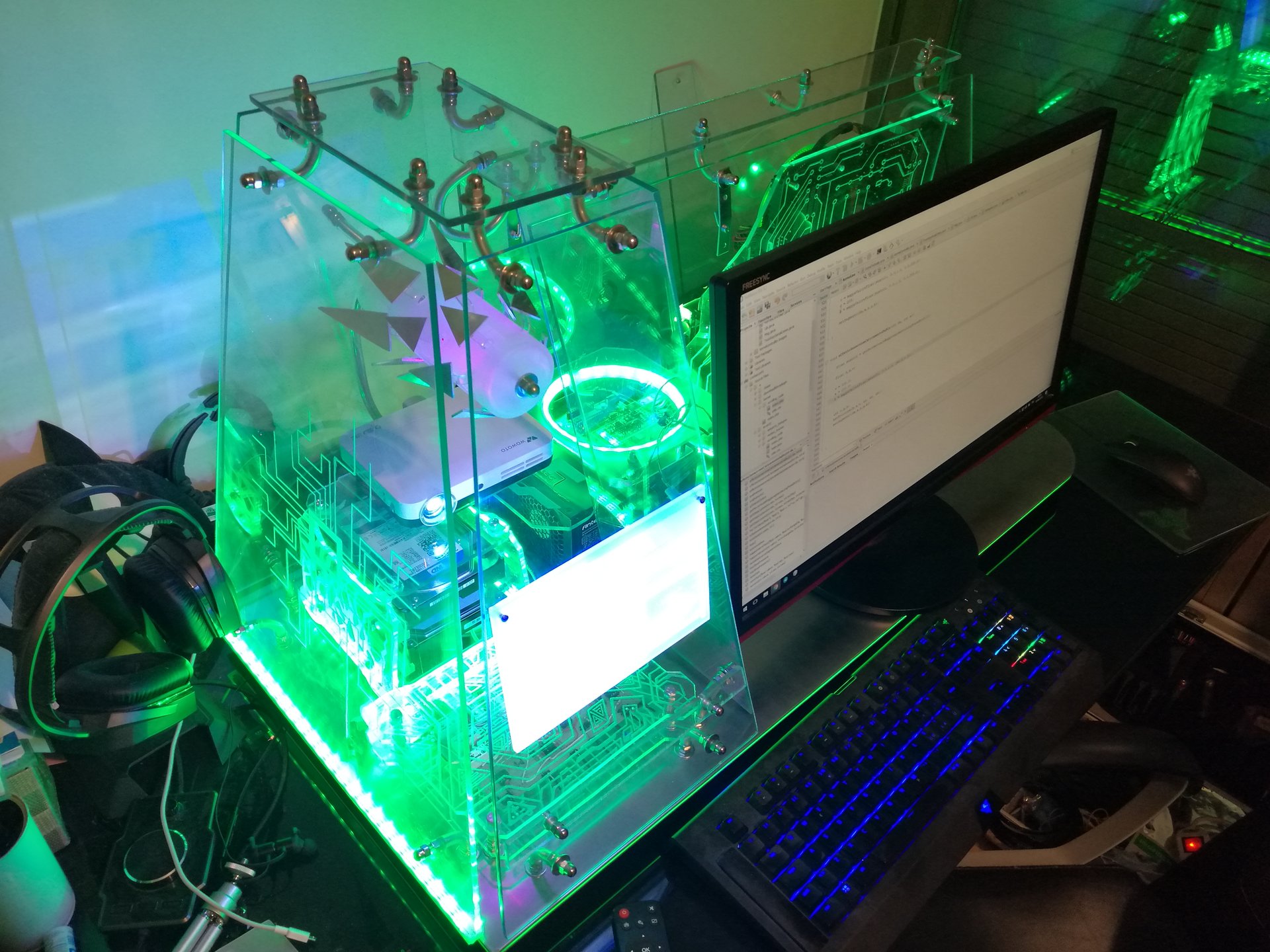
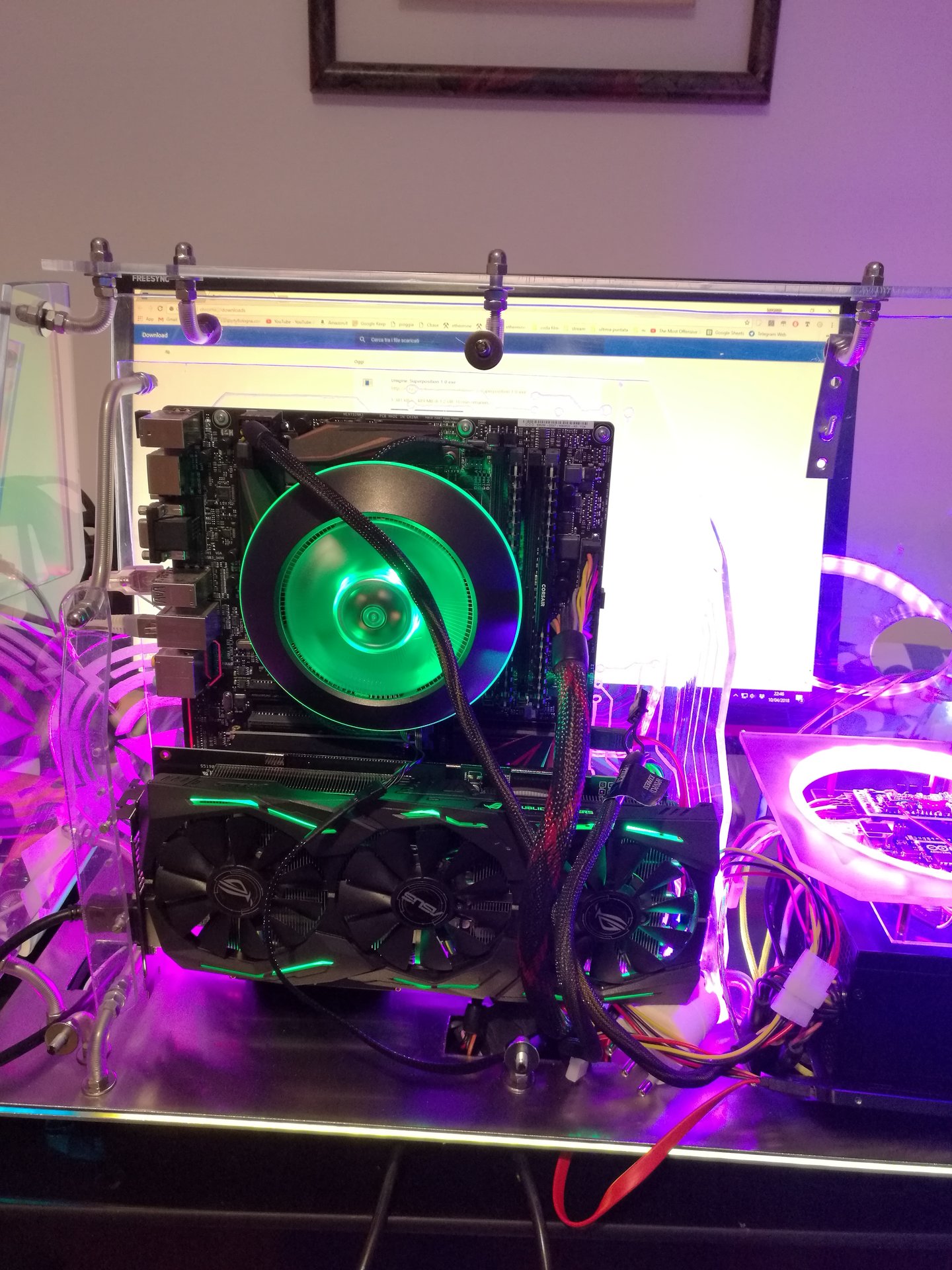
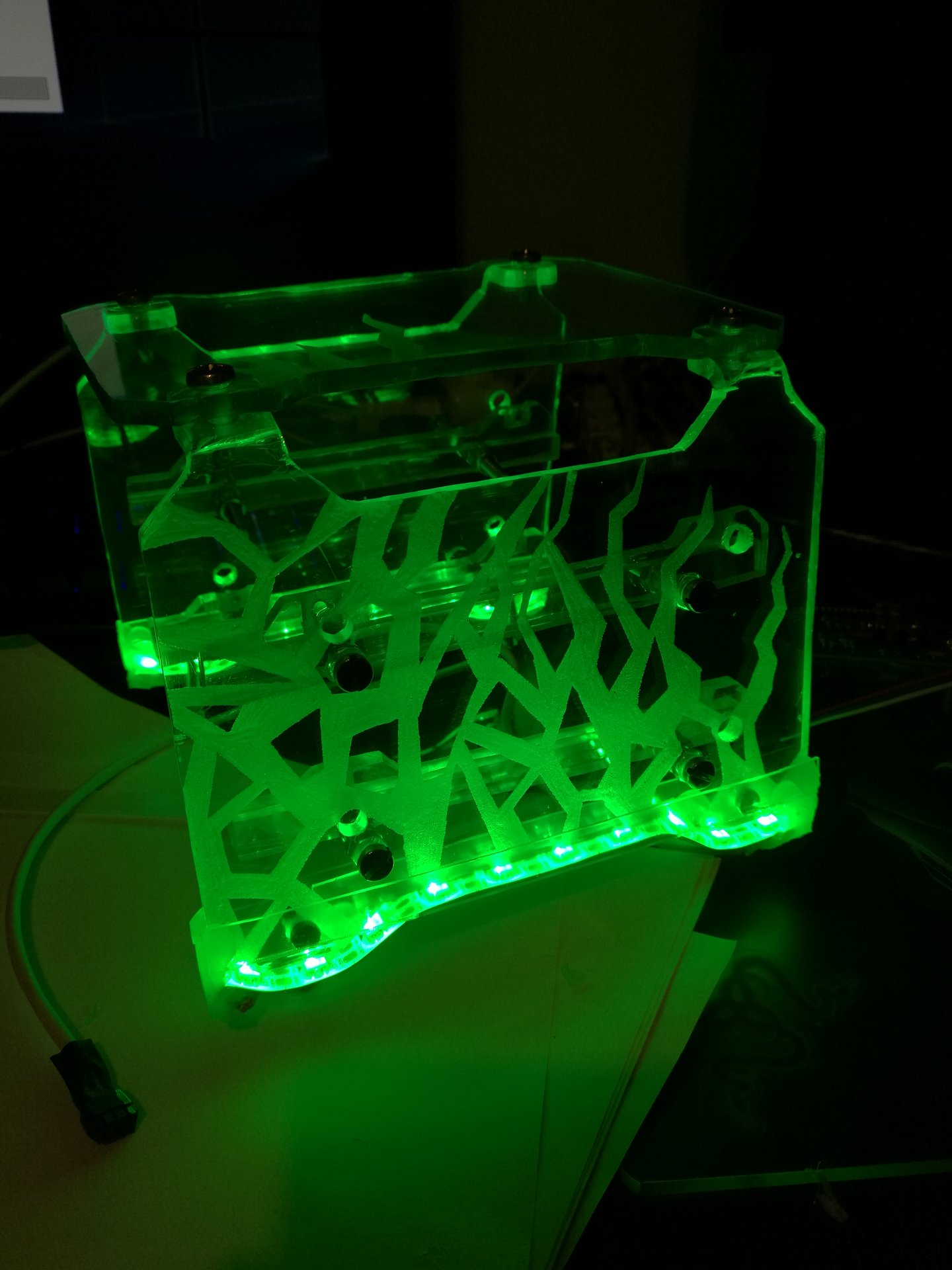
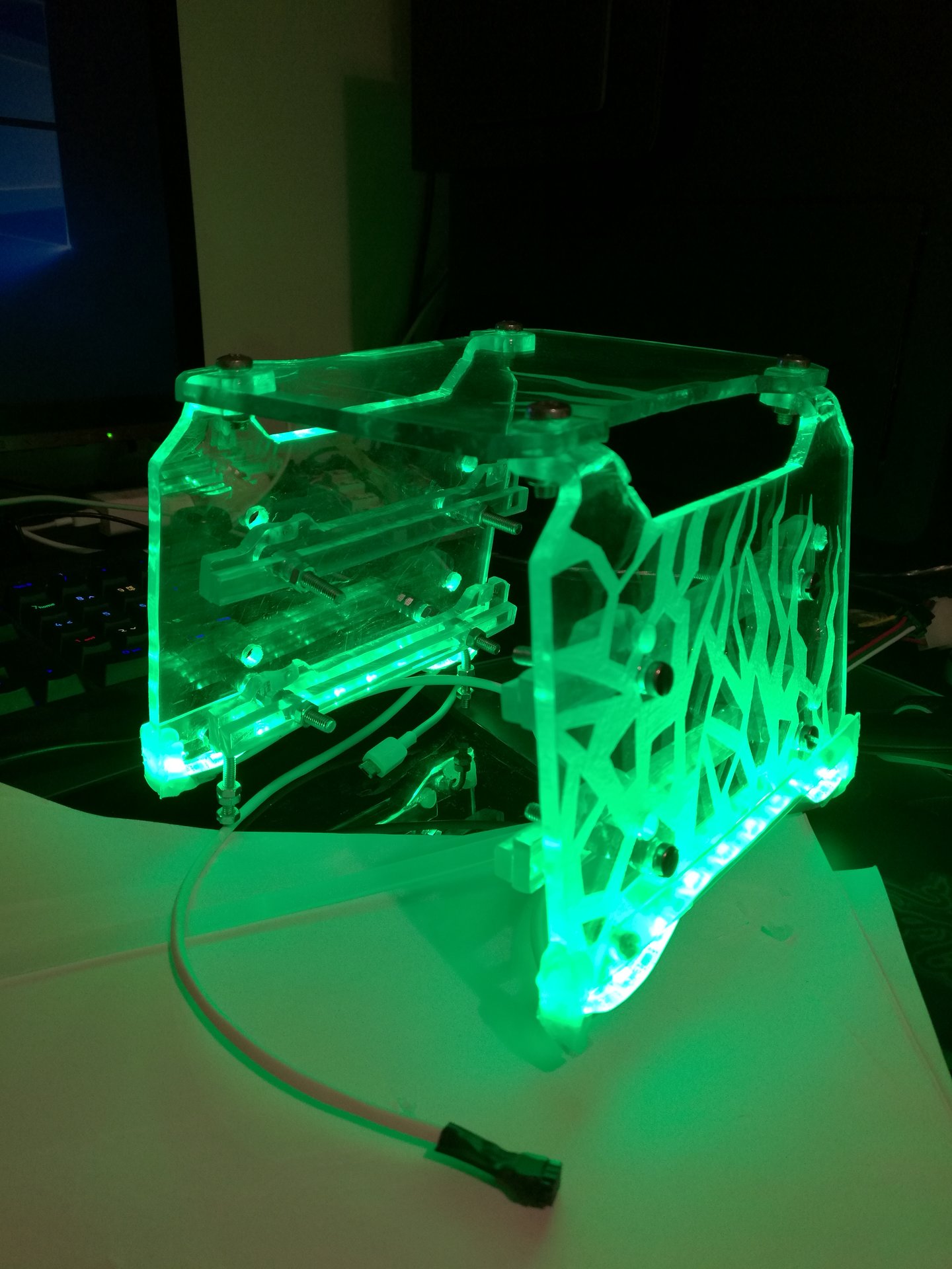
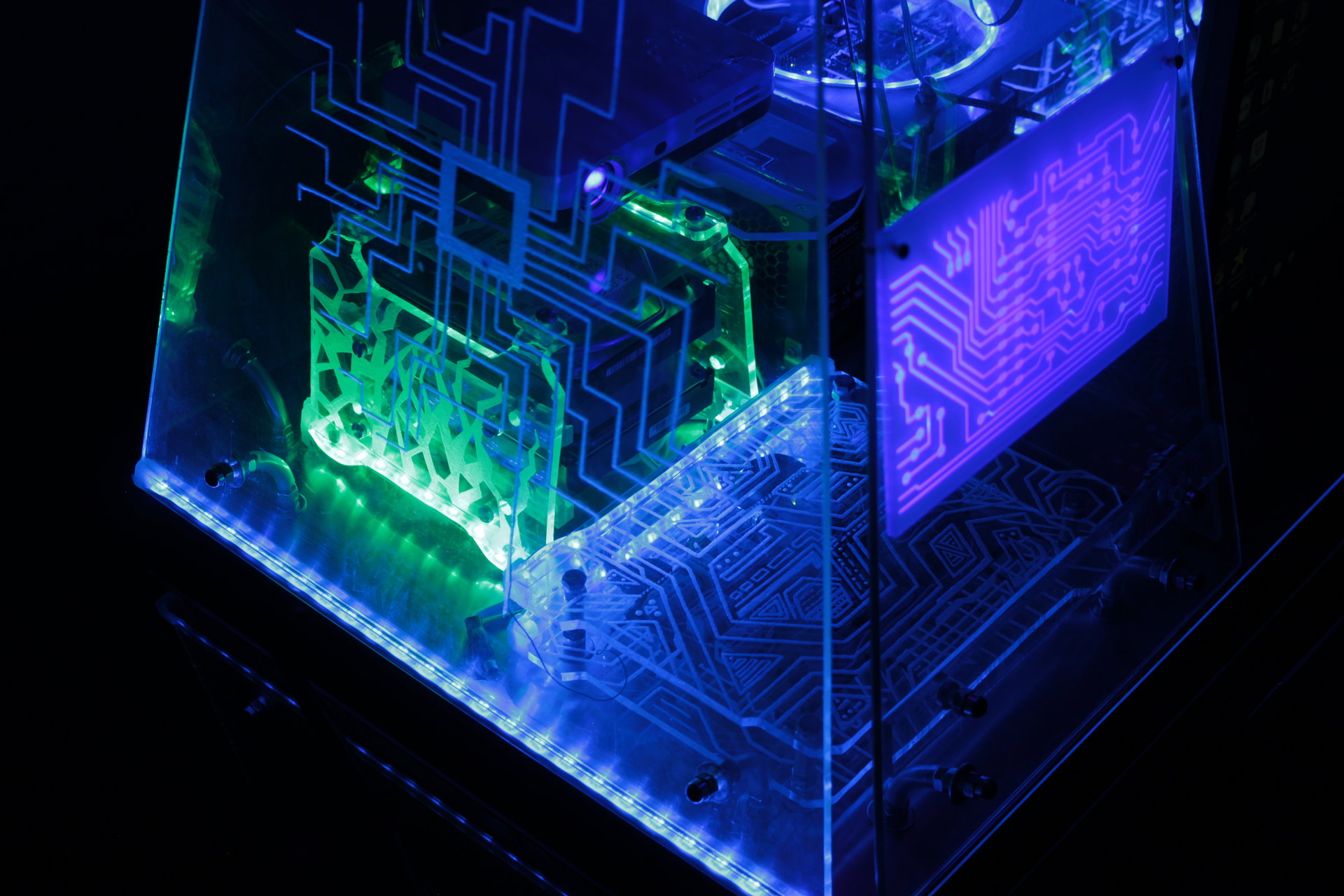
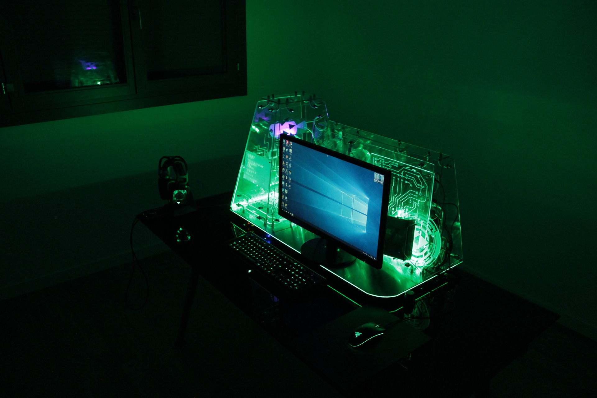
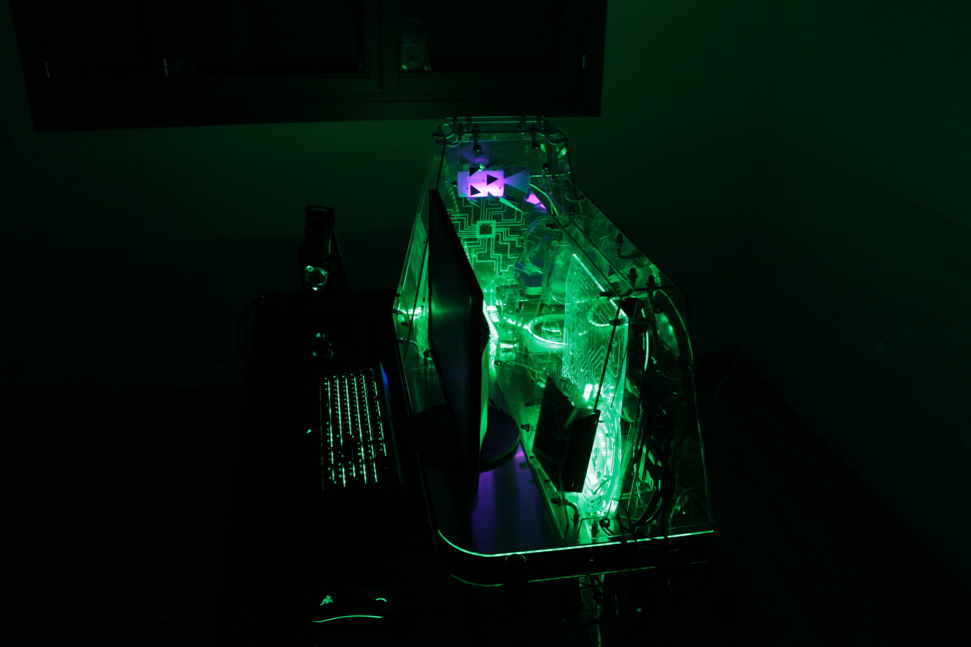
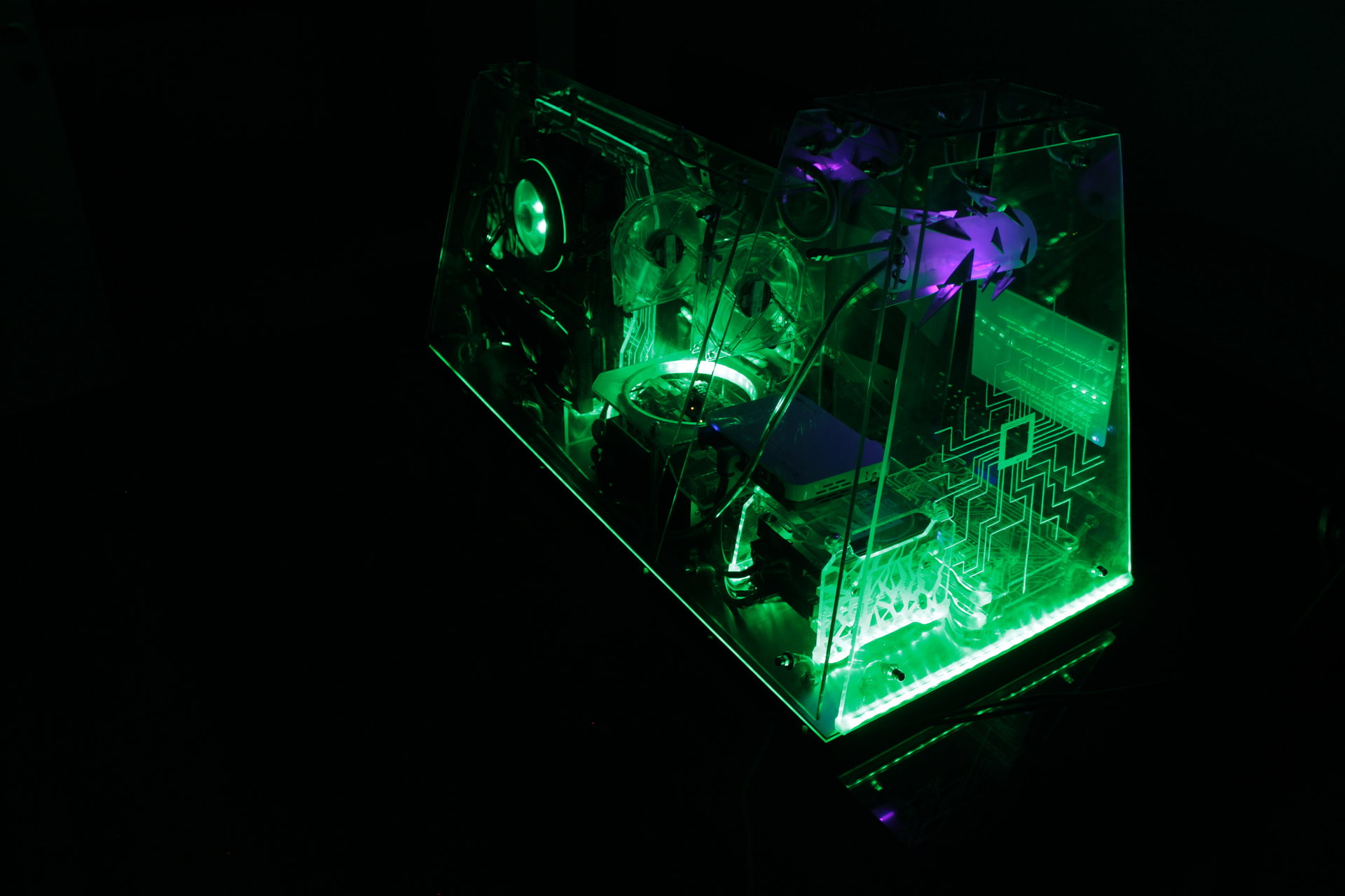
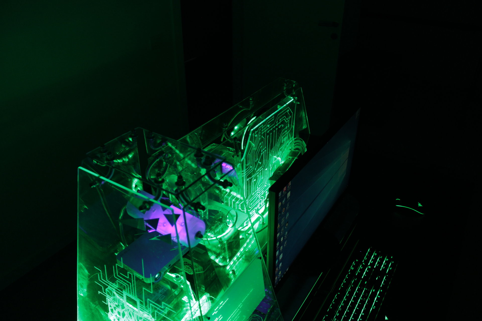
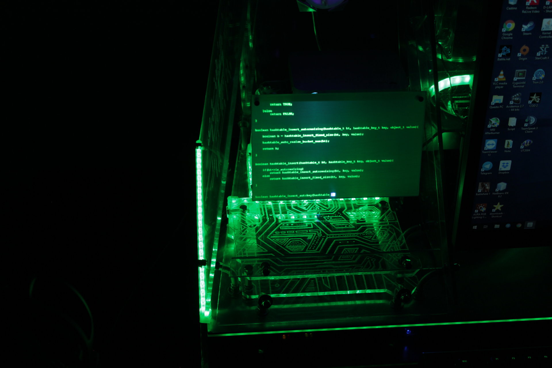
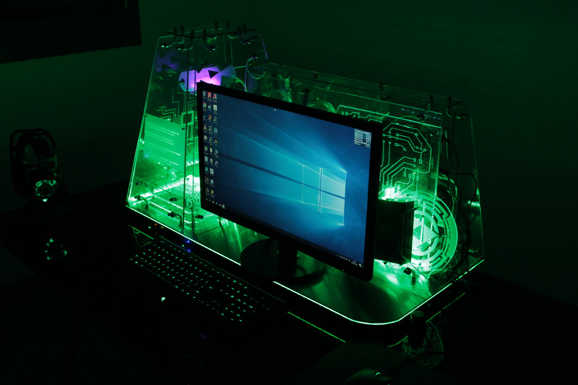
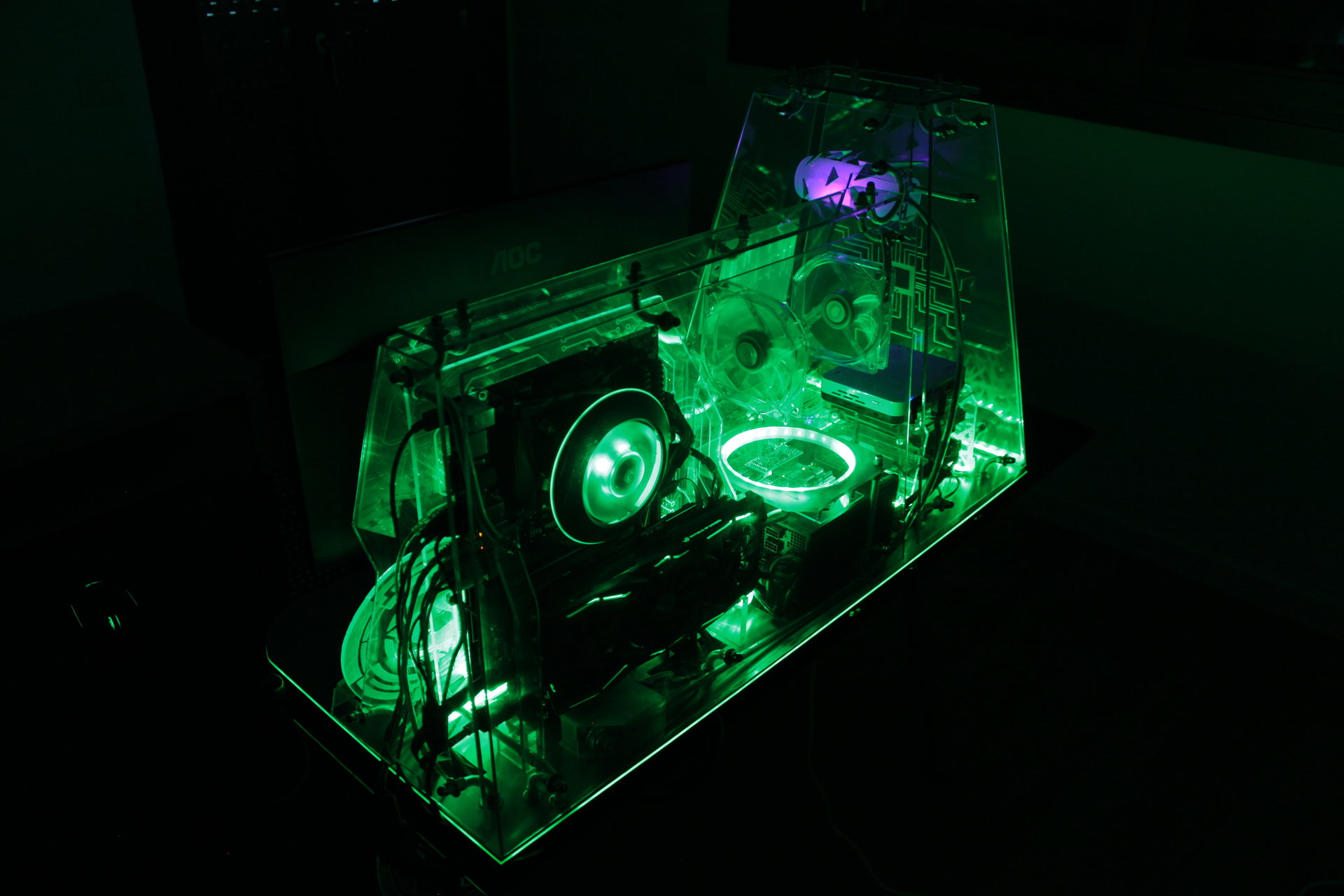
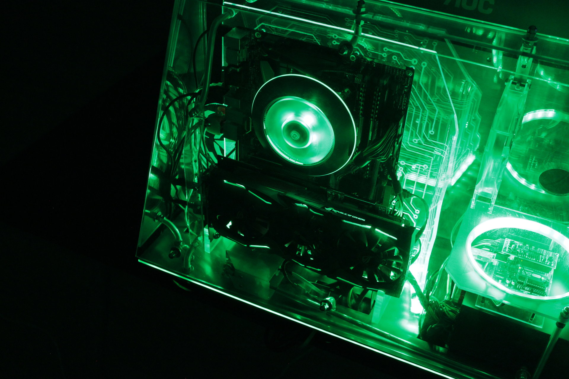
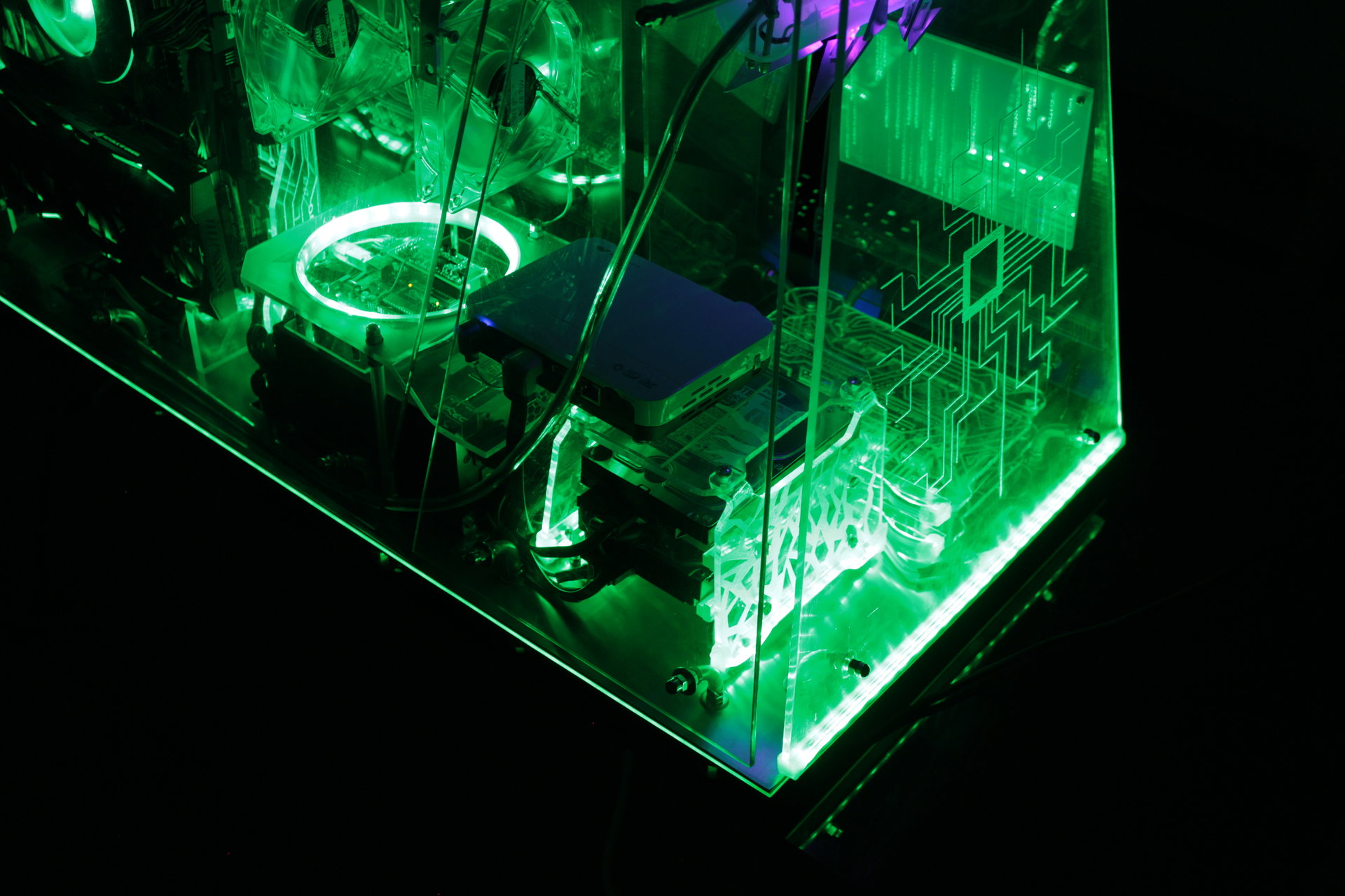
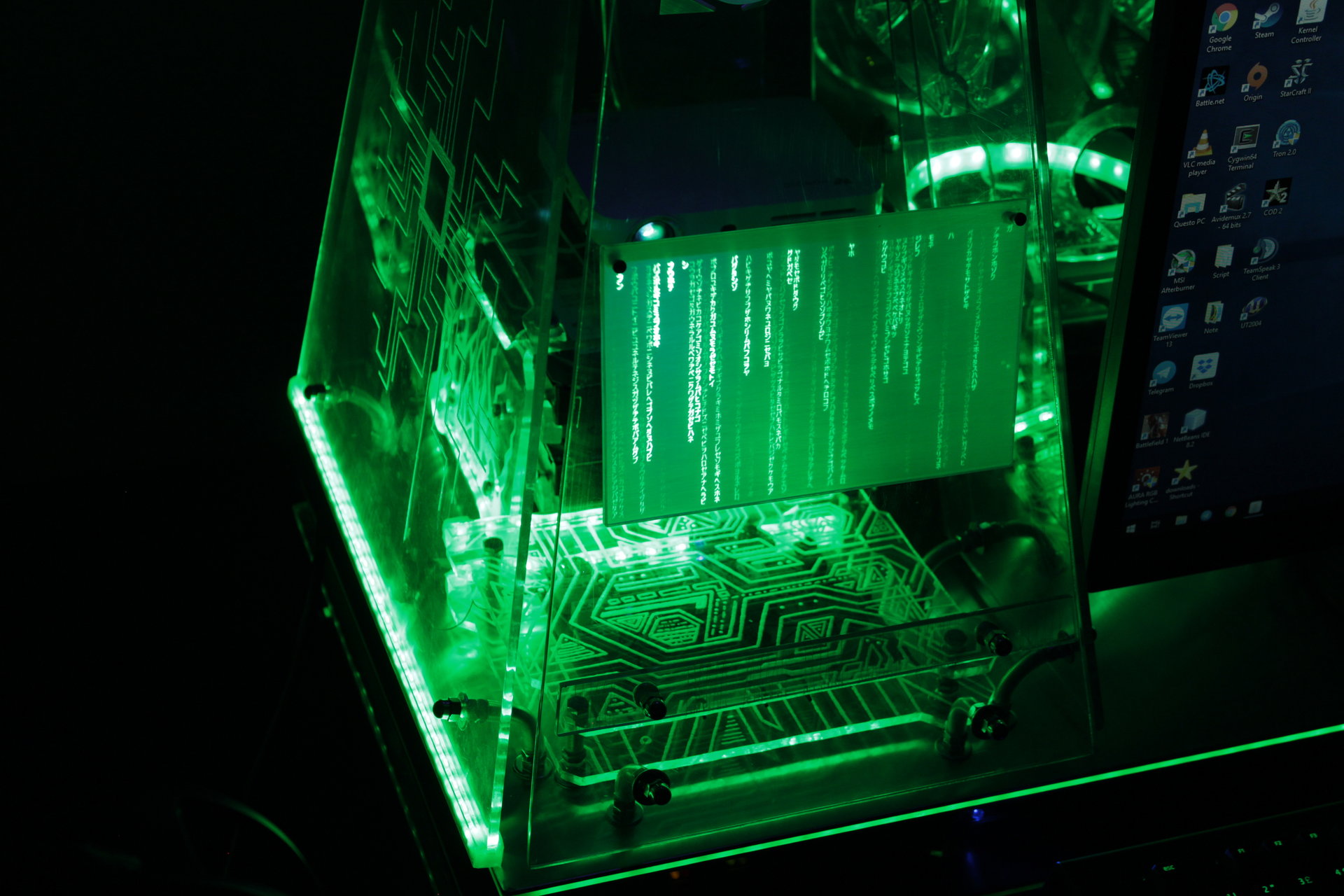
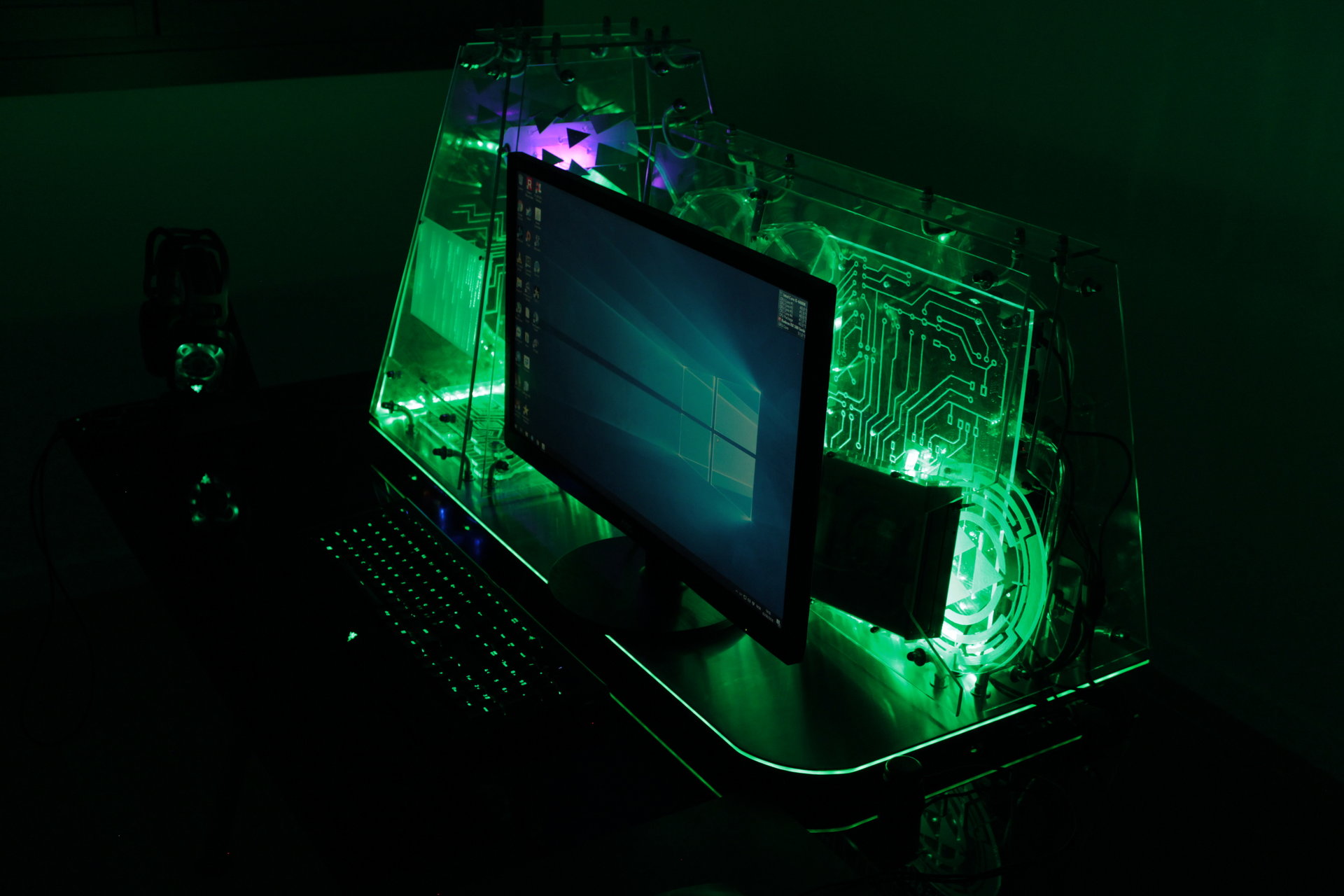
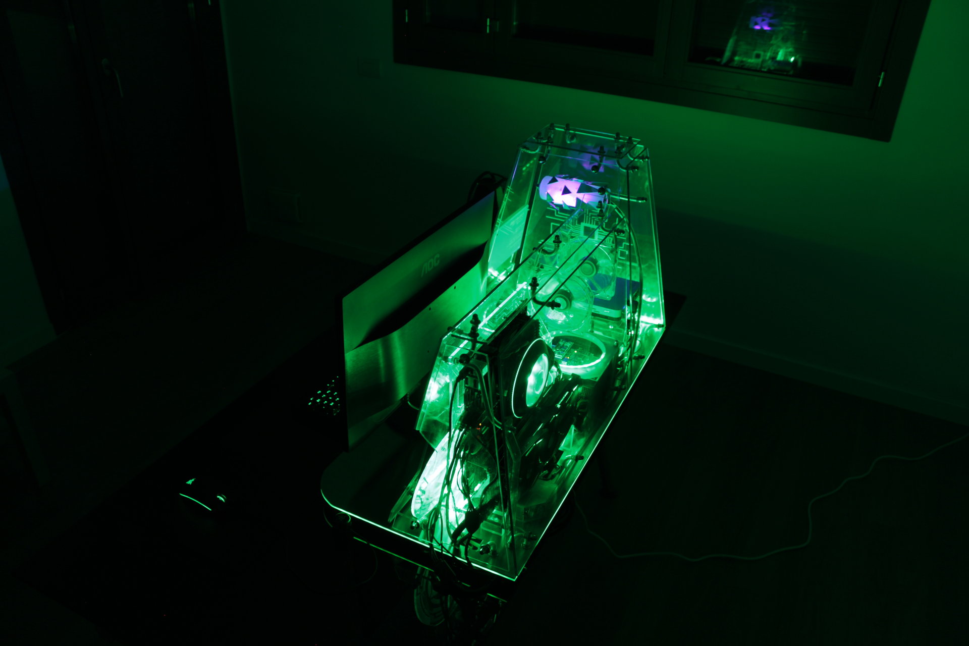
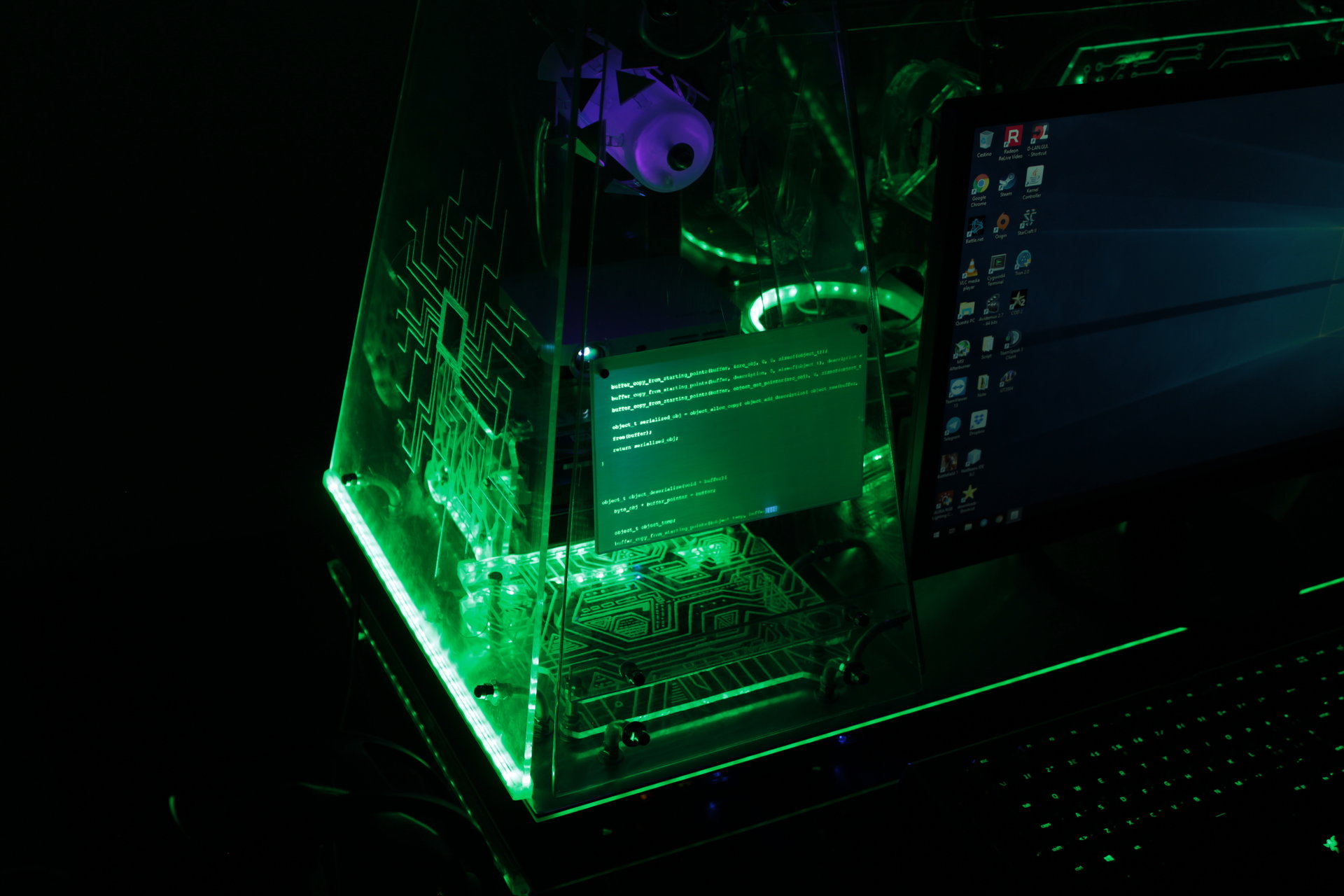
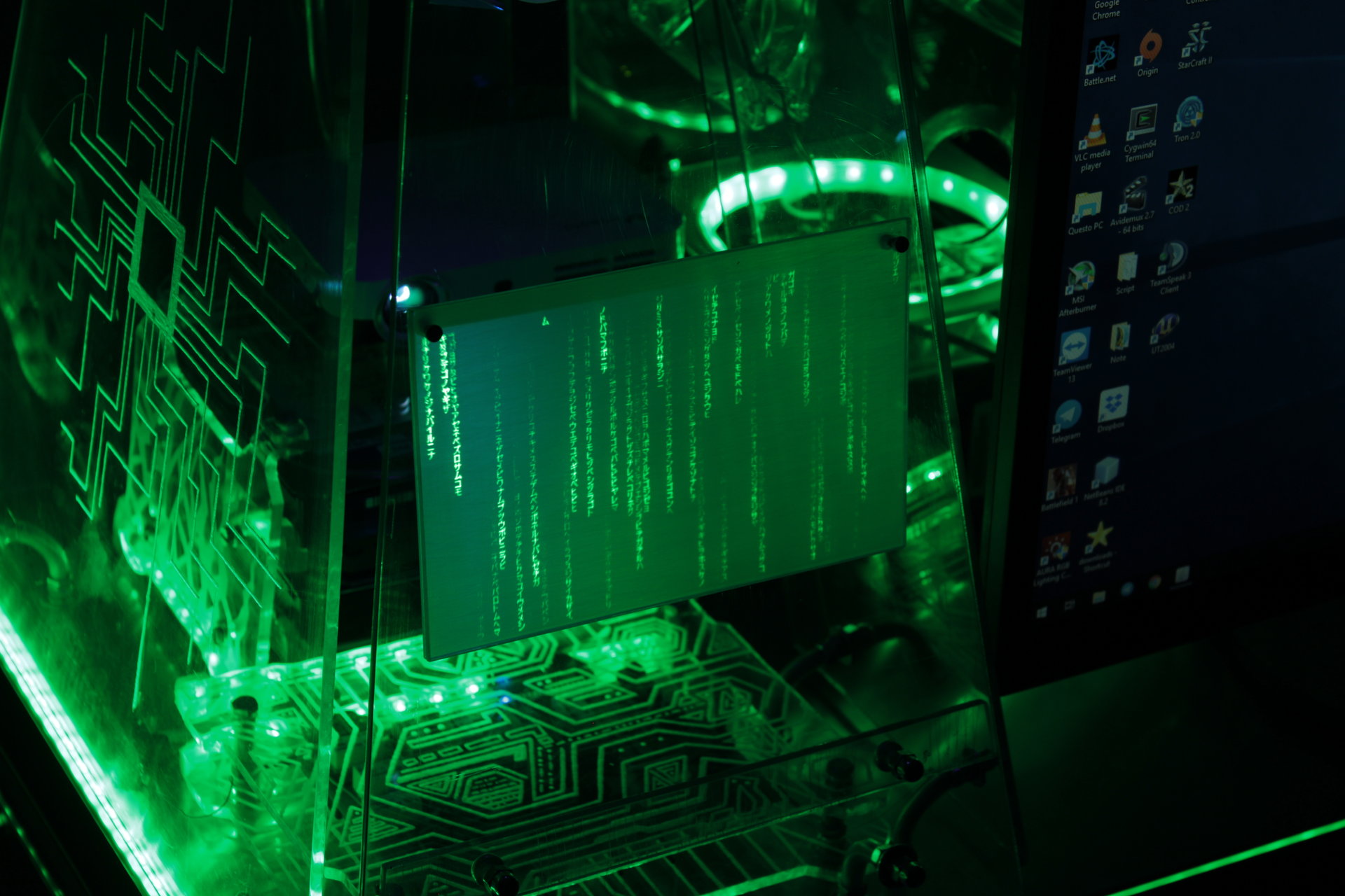
Green states:
– all green
– Arduino ring with 1-3 rotating green pixel trails
– projector animation: scrolling code, or Matrix-style falling code
– proximity sensor “charging” effect: green->white


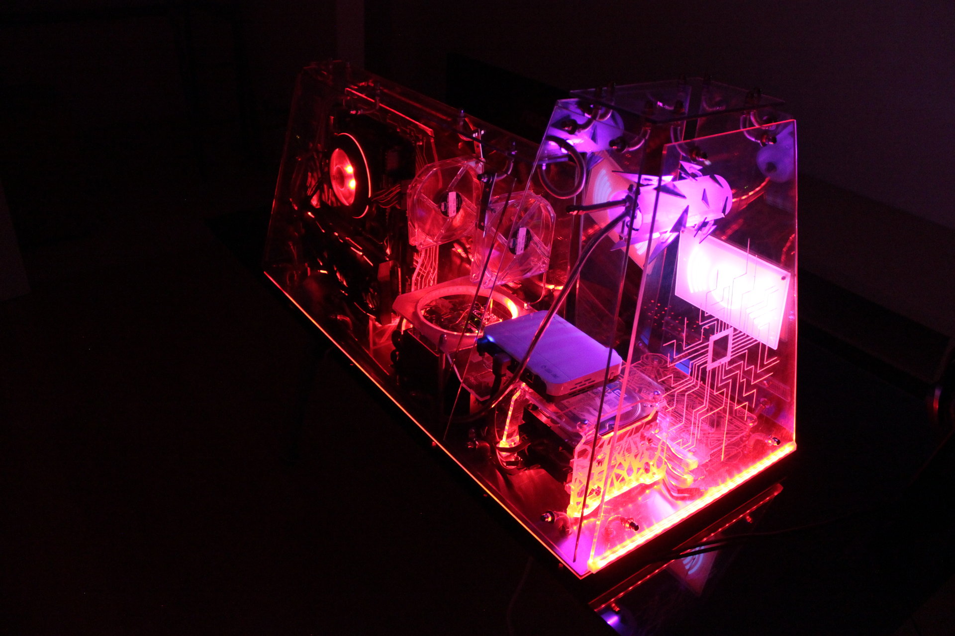
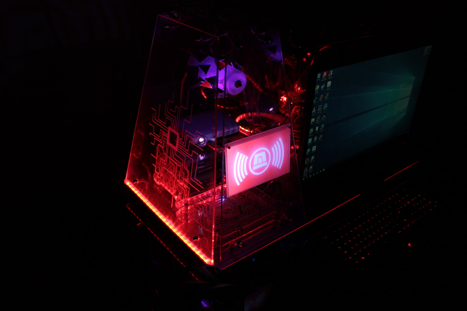
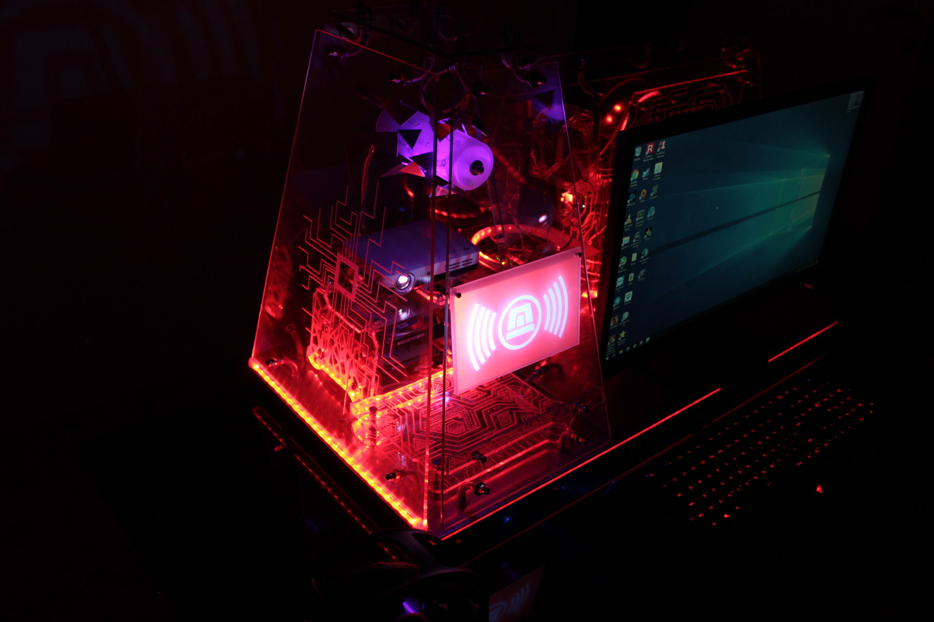
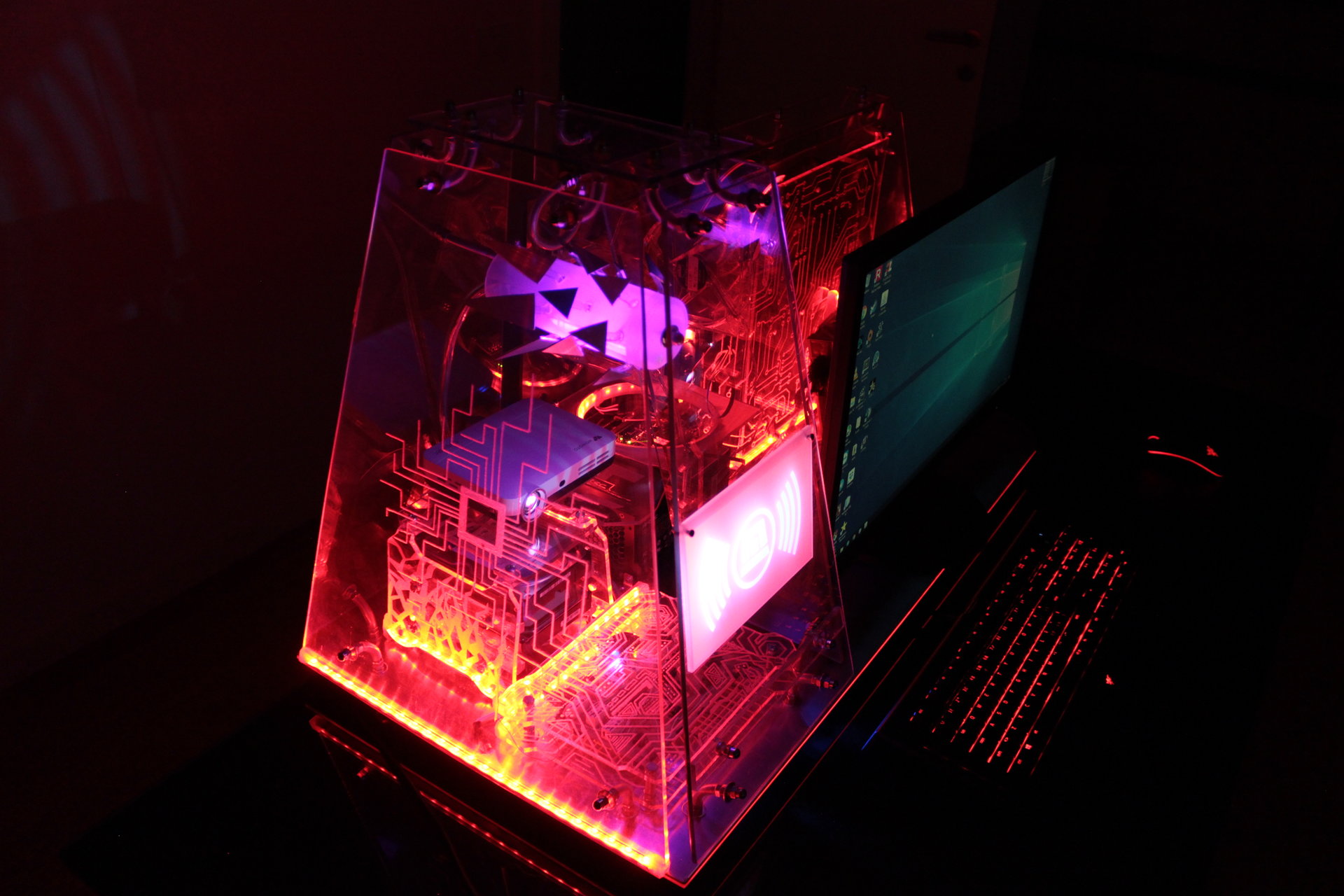
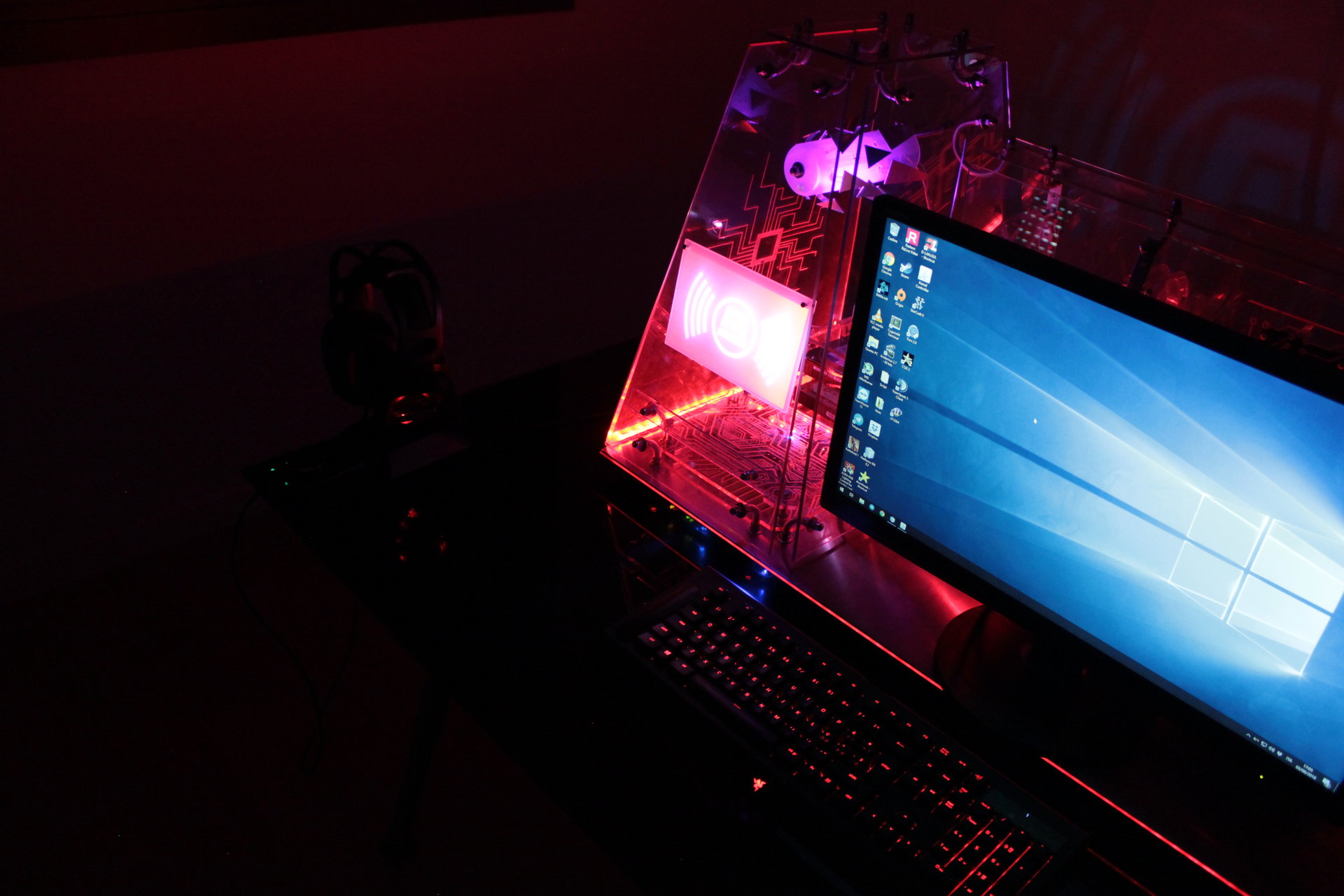
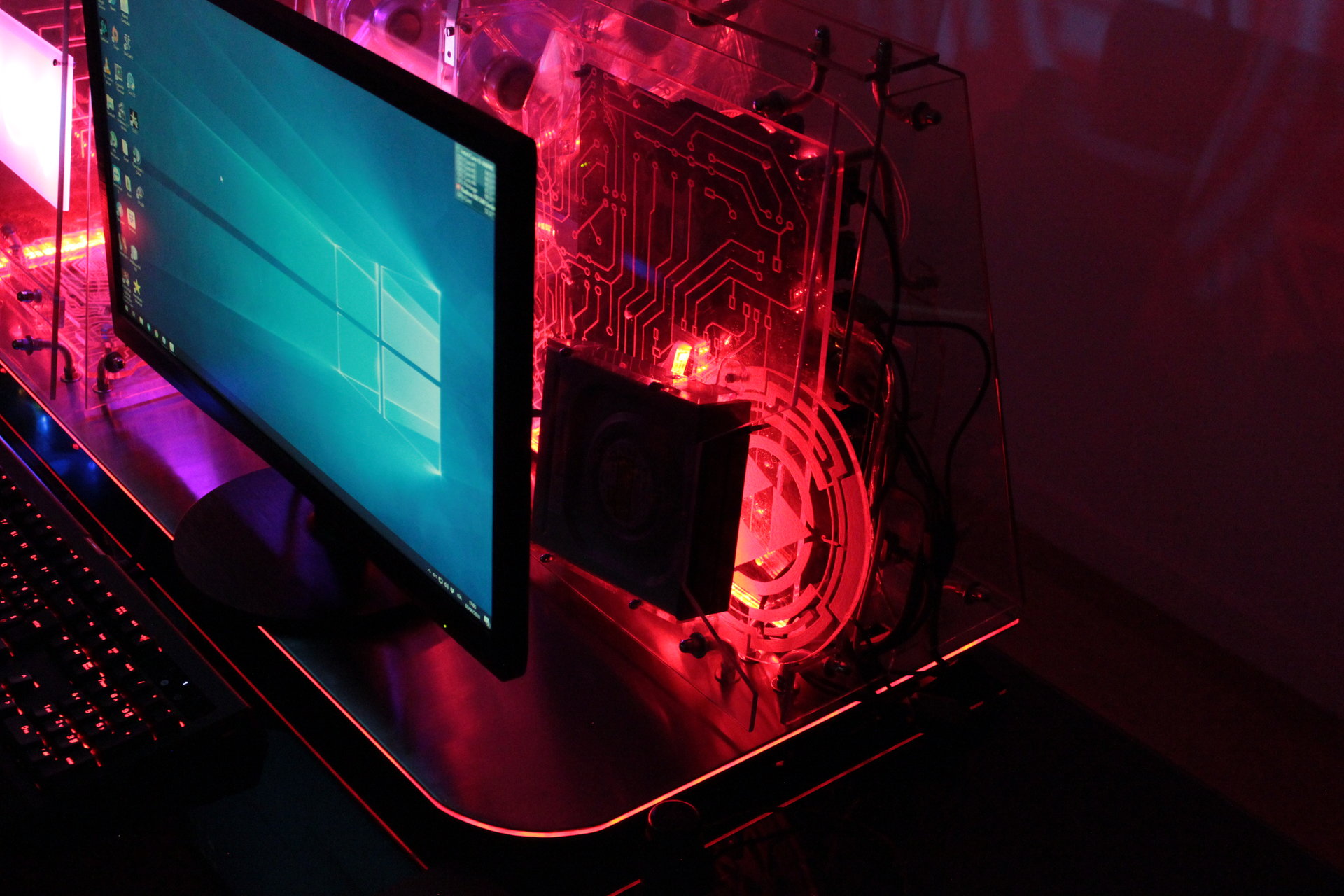
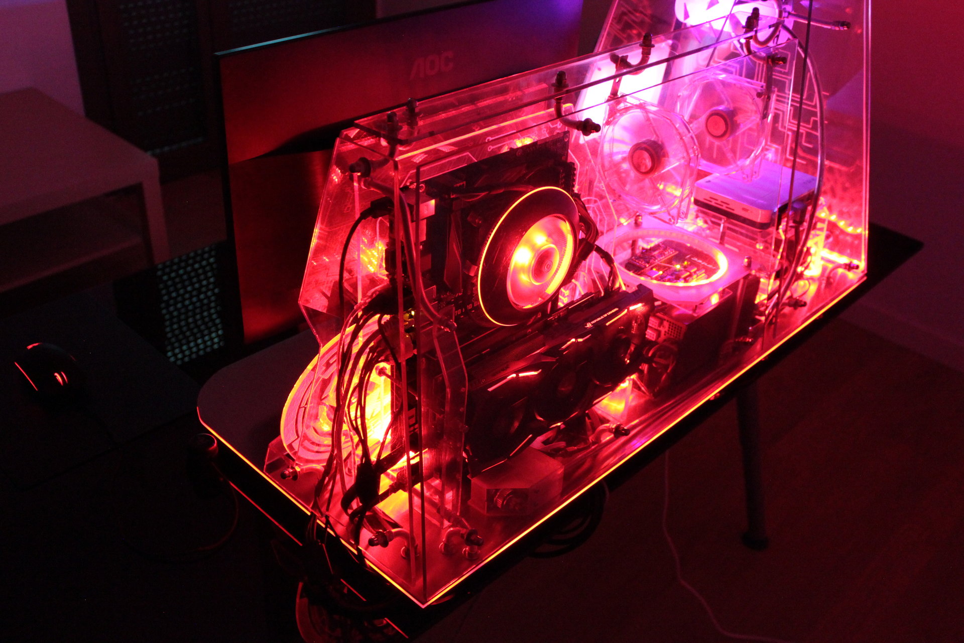
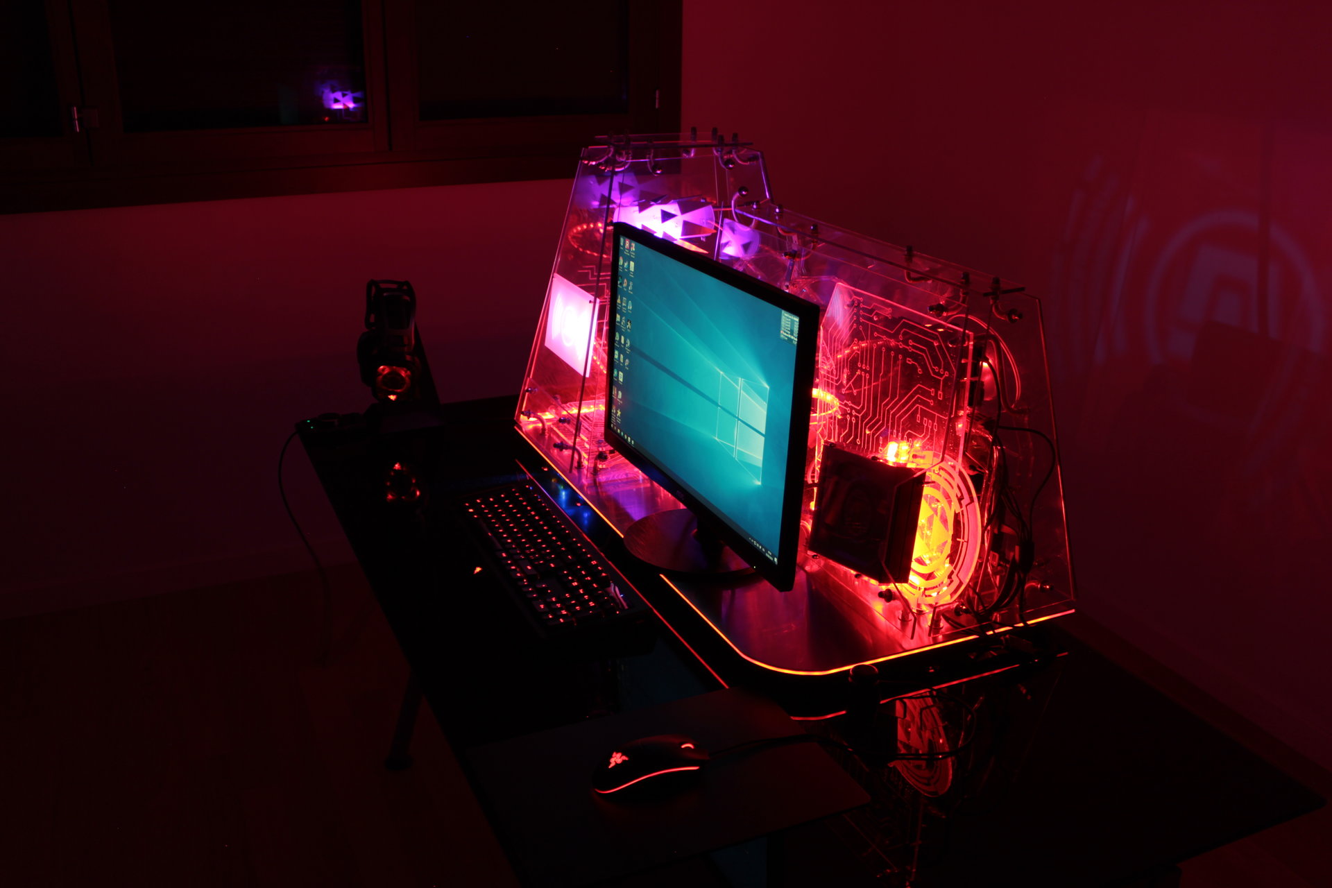
Red state:
– all pulsating red (alarm-style)
– Arduino ring with 1 rotating red pixel trail, like an alarm signal
– projector animation: flashing red alarm signal
– proximity sensor “charging” effect: “incandescent” effect, red->yellow->white


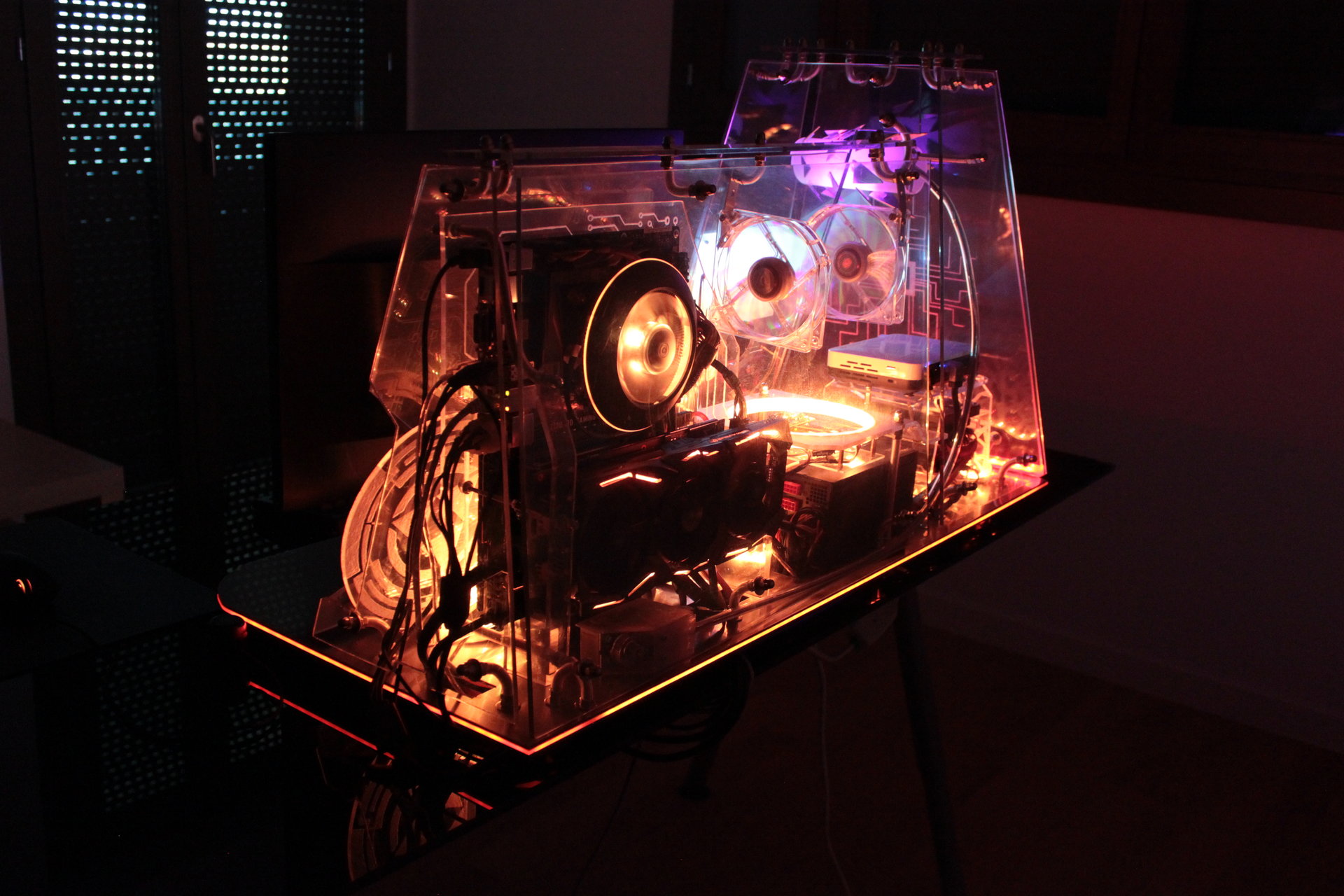
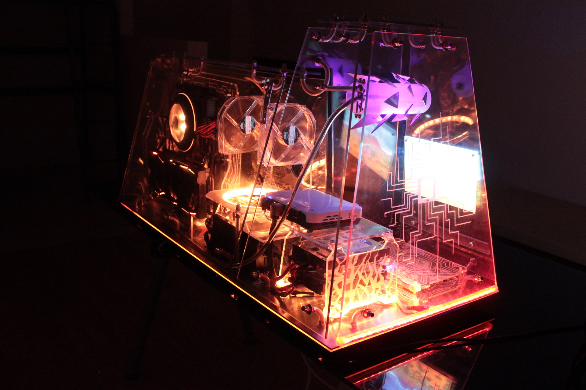
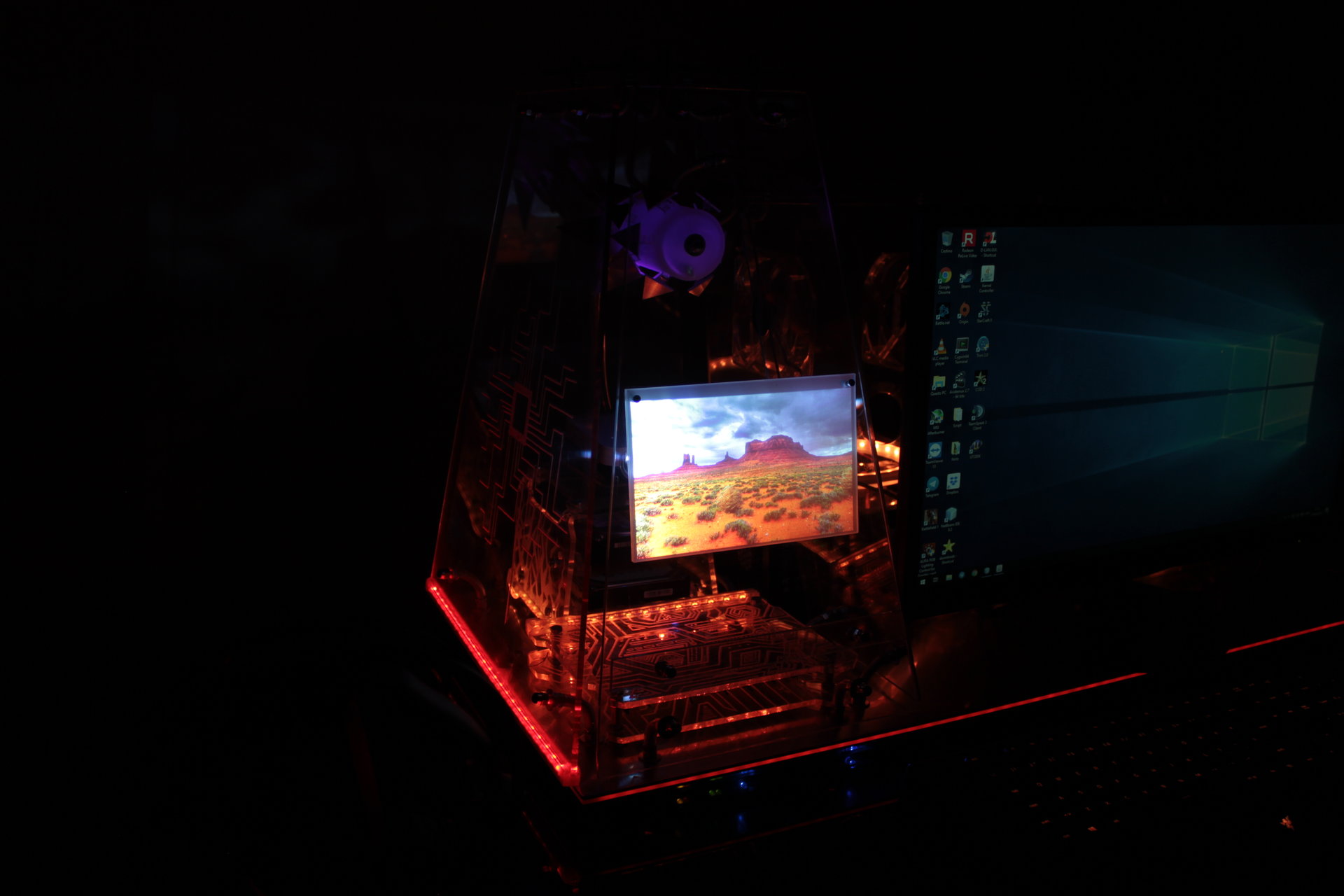
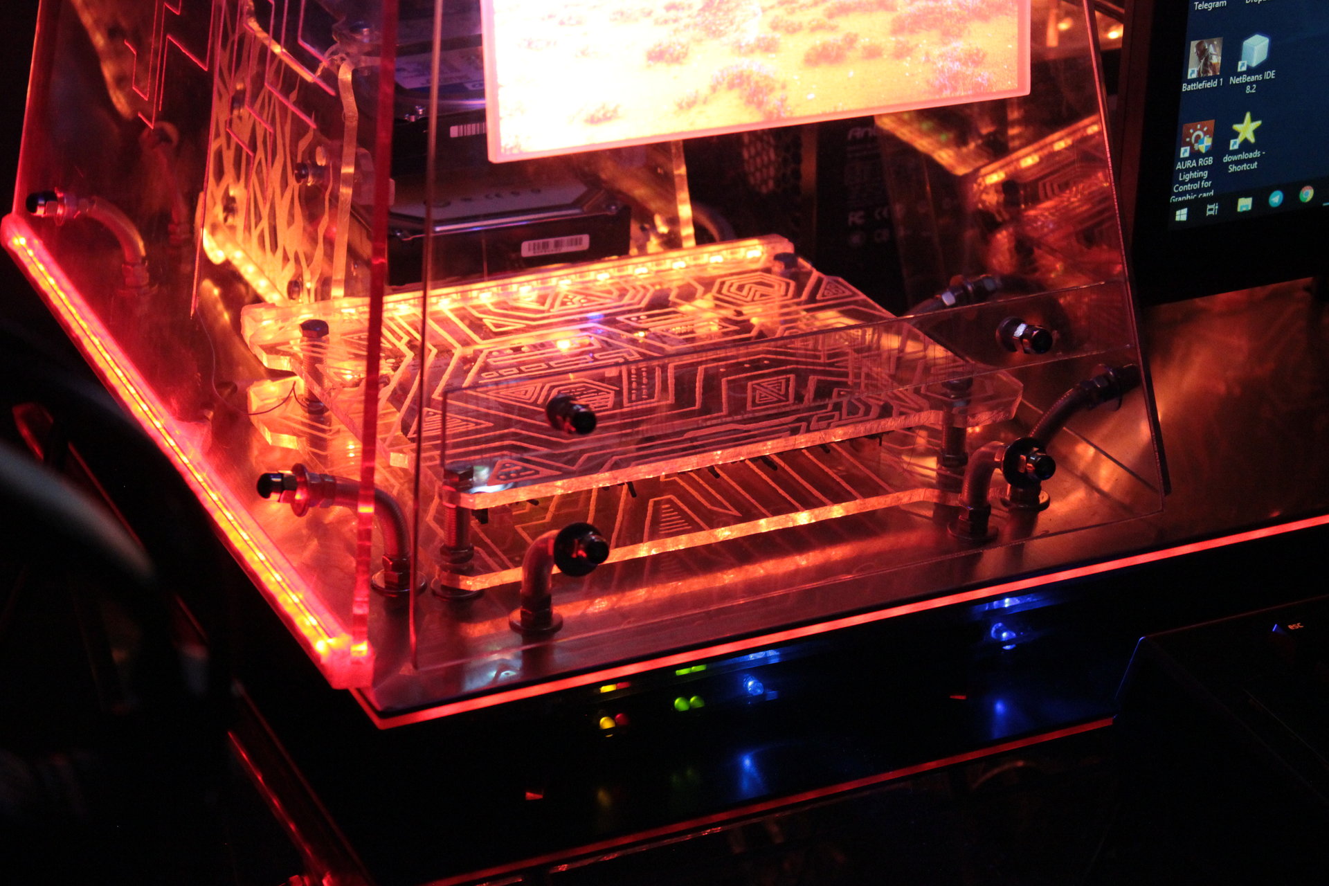
Desert state:
– all orange
– projector animation: desert with rolling tumbleweeds 😀
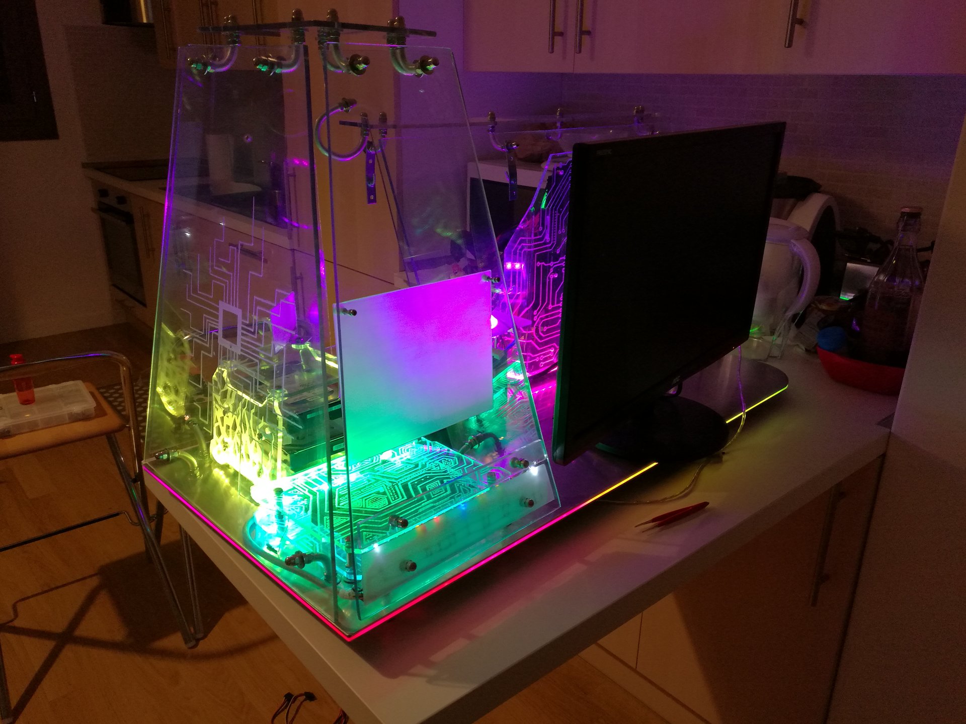
Colourful states:
– lighting with constant fluid color hue cycling on all the led strips