The touch sensors part of the circuit was already completed, but in the circuit there wasn’t all the parts that link the relays to the various devices of the case (the diagram shown above), so i completed this part of the circuit.
These are the functions of the 7 touch sensors:
– power on
– reset
– “mysterious device” on/off
– proximity sensor on/off
– 5/12v fans speed
– audio on/off
– lighting on/off
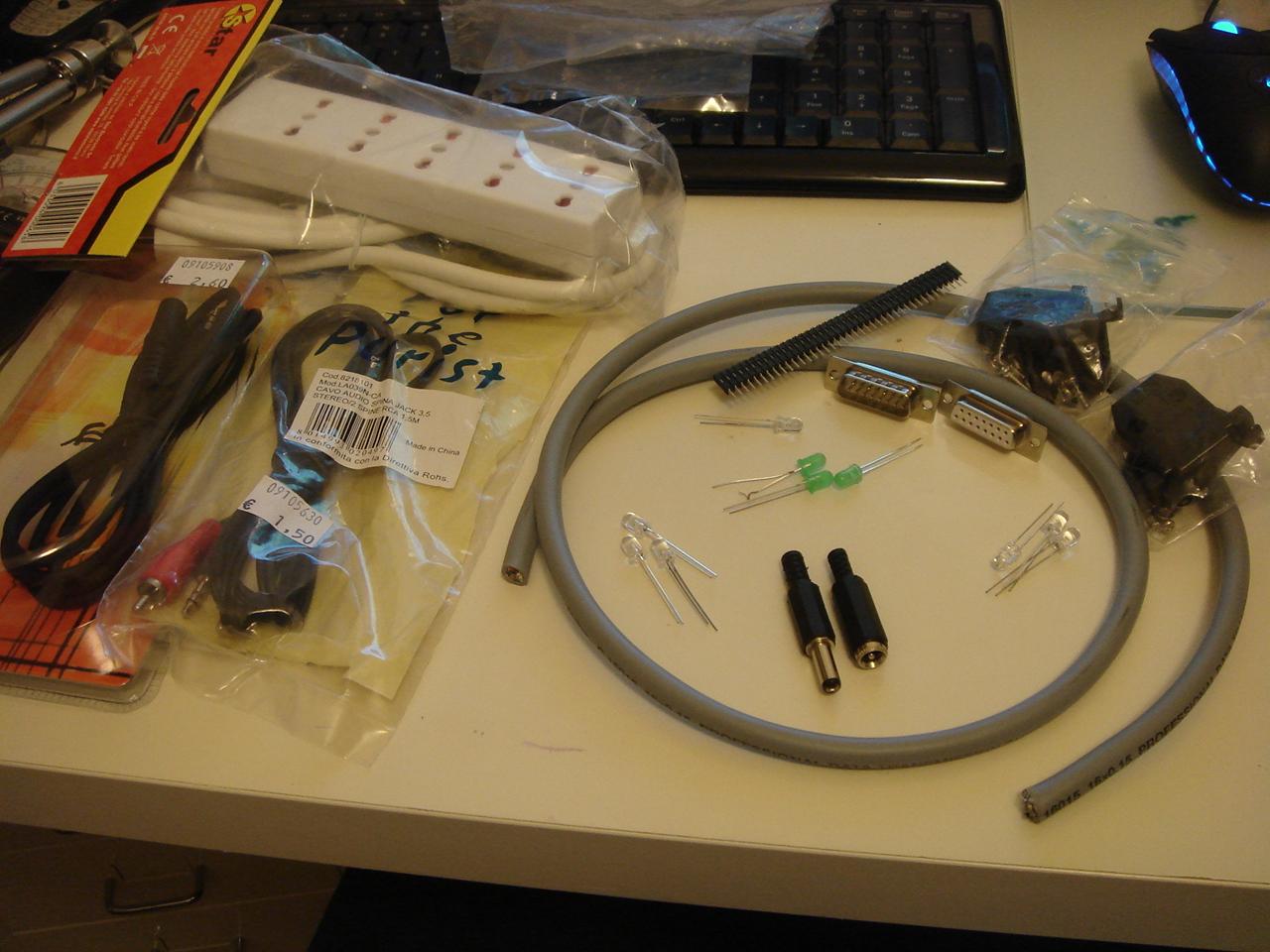
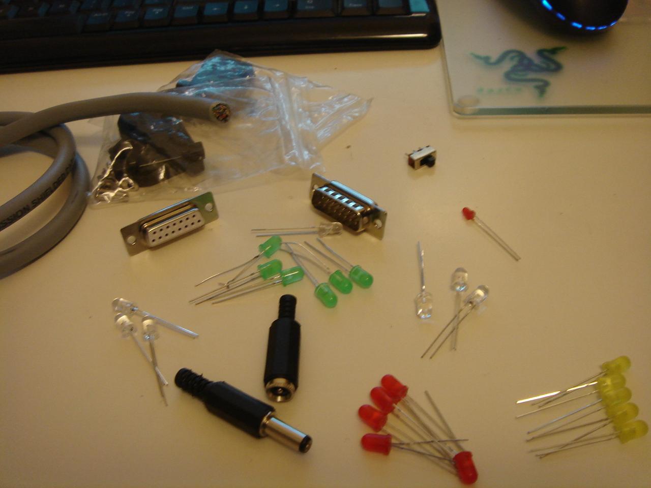
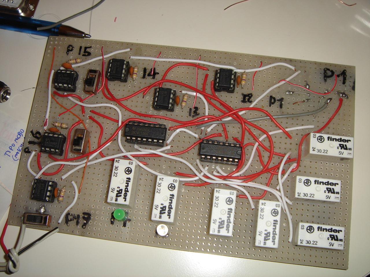
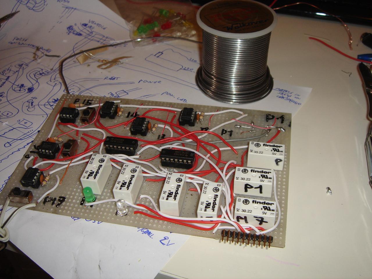
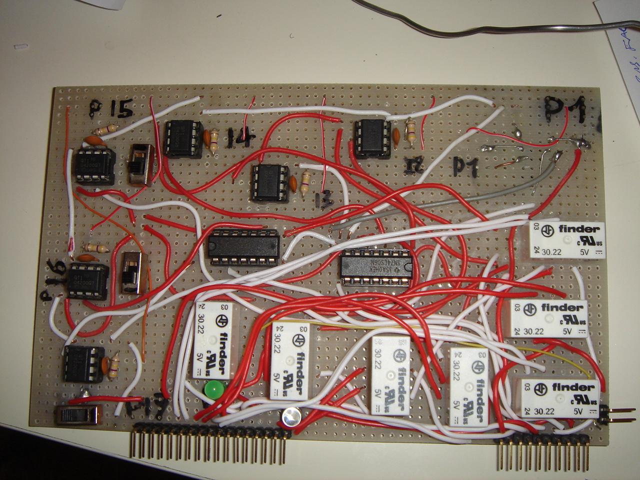
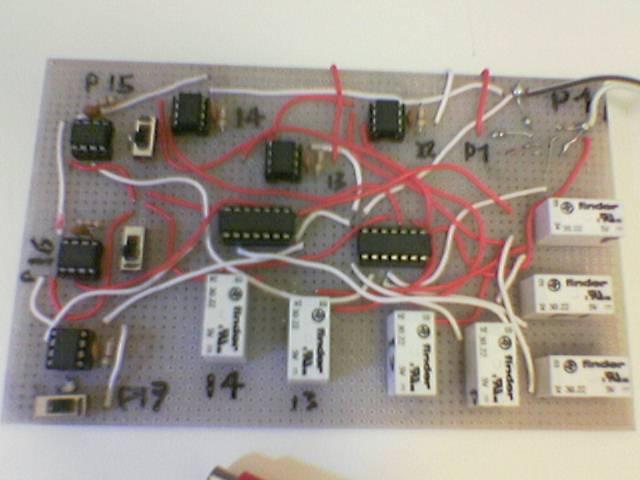
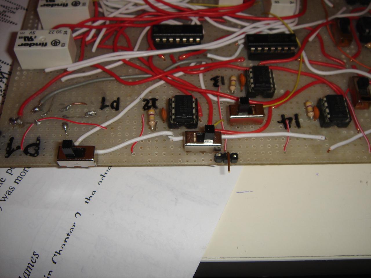
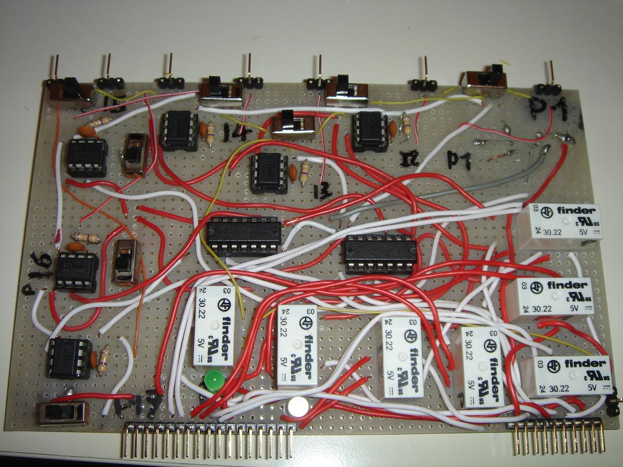
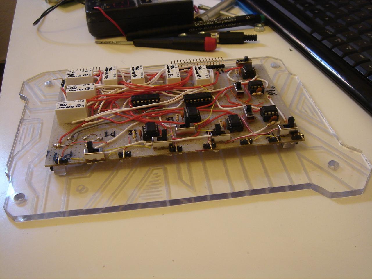
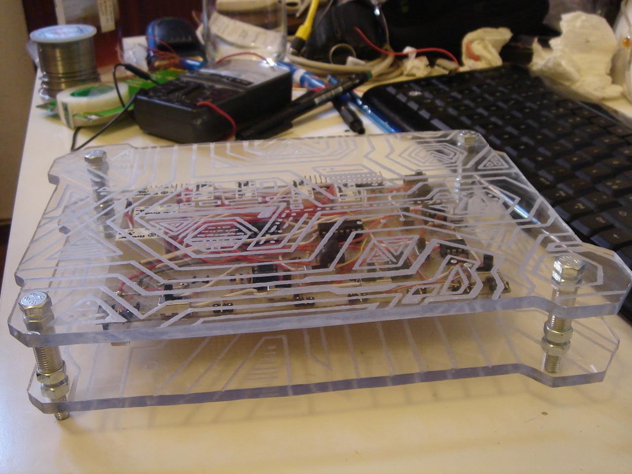
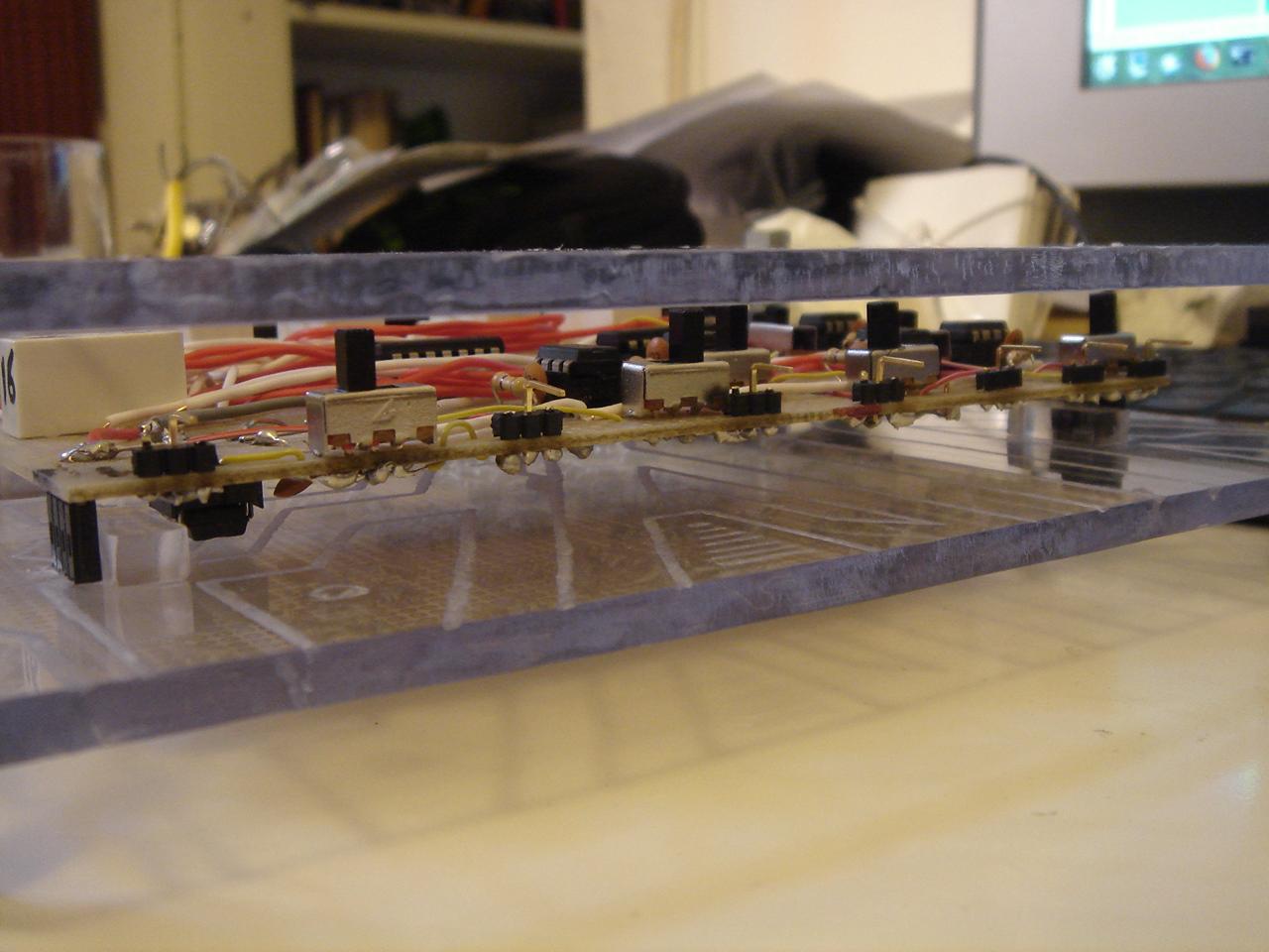
I bought some components, and I had left the circuit in this state:
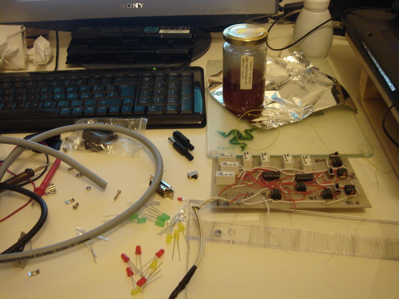
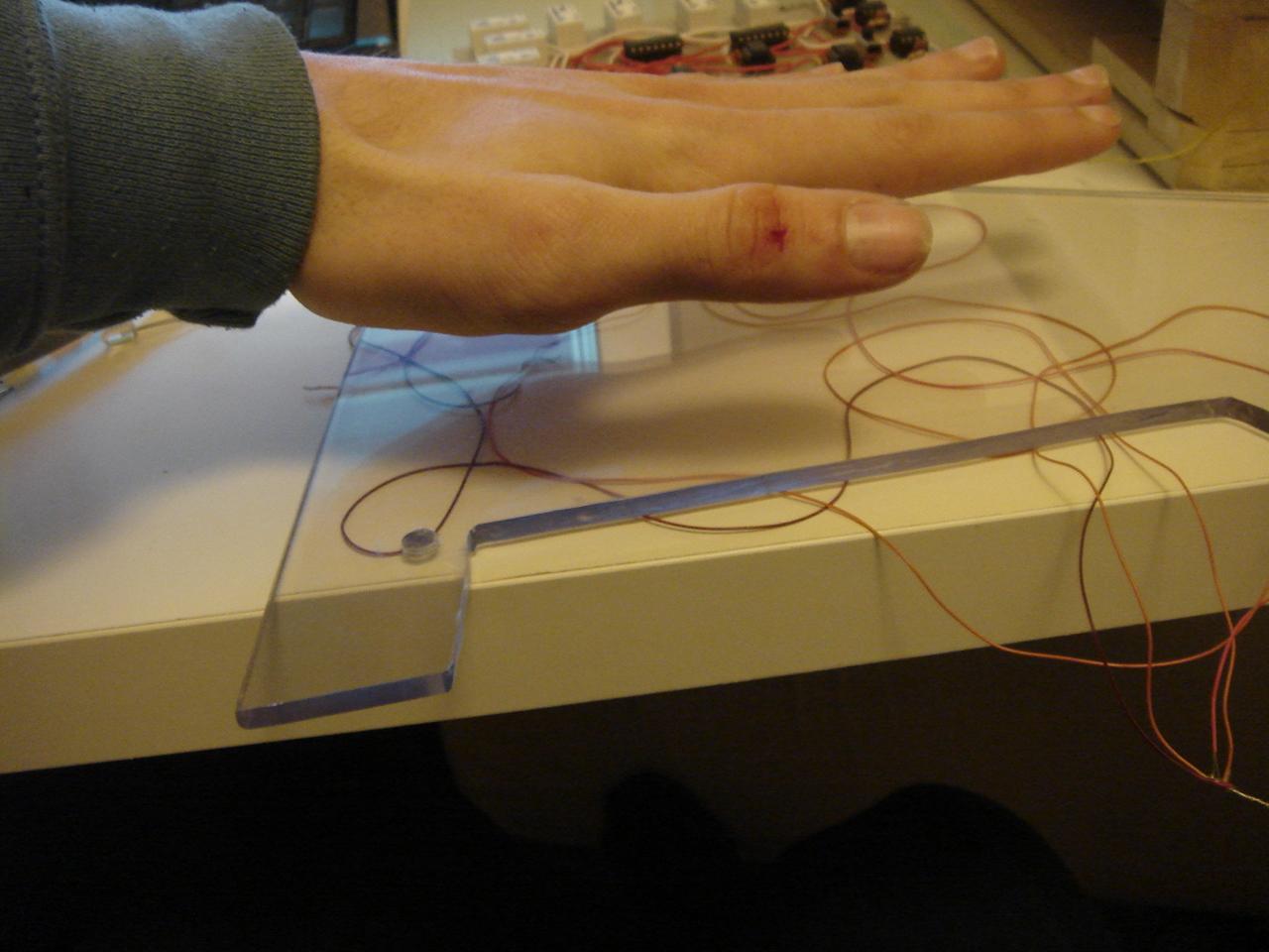
I have done some tests for the proximity sensor (which is simply a touch sensor like the others, but with a bigger area)
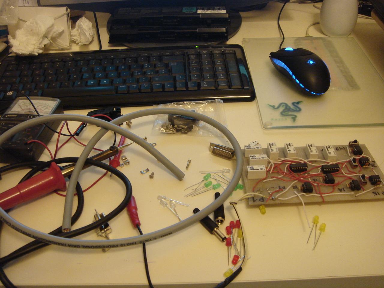
a photo of my electronic lab:

…and one of my workshop:
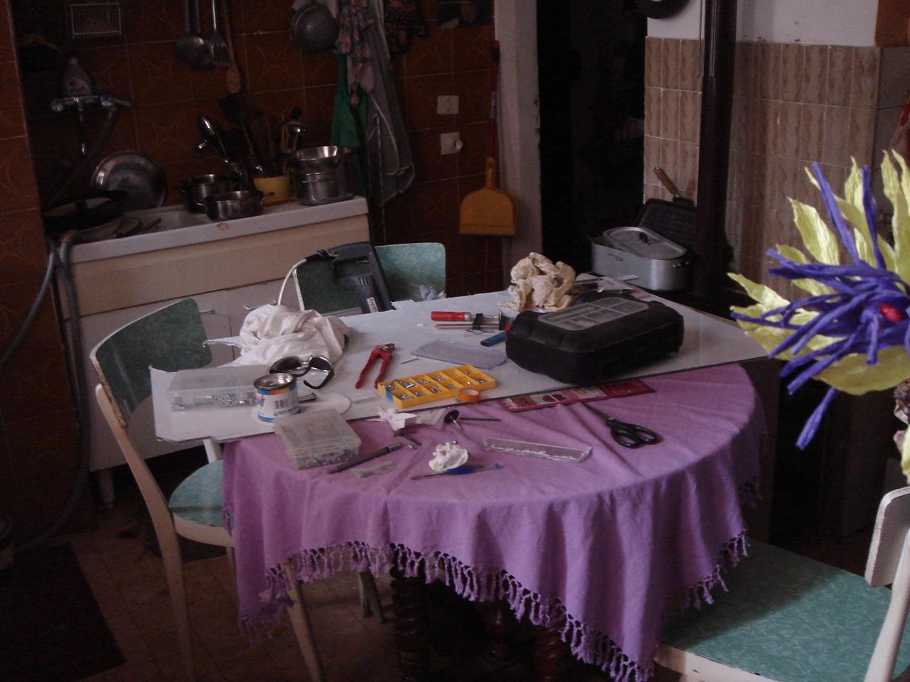
…very, very professional 😀 😀 😀
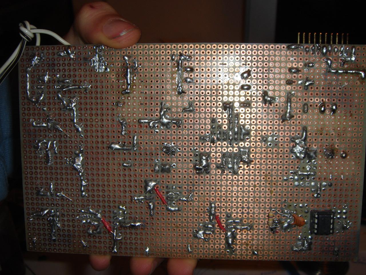
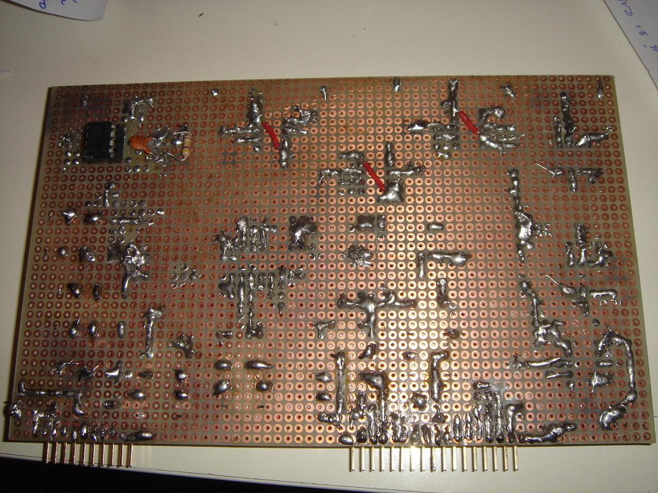
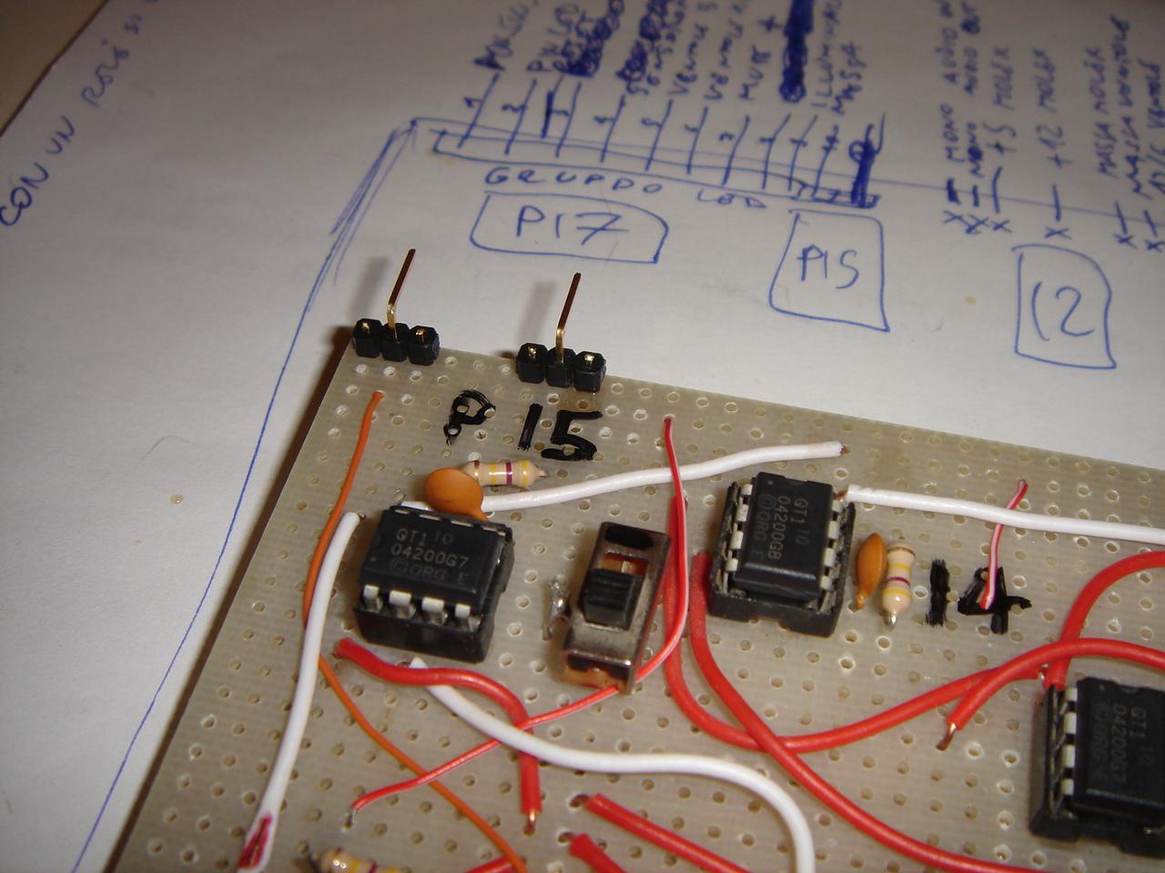
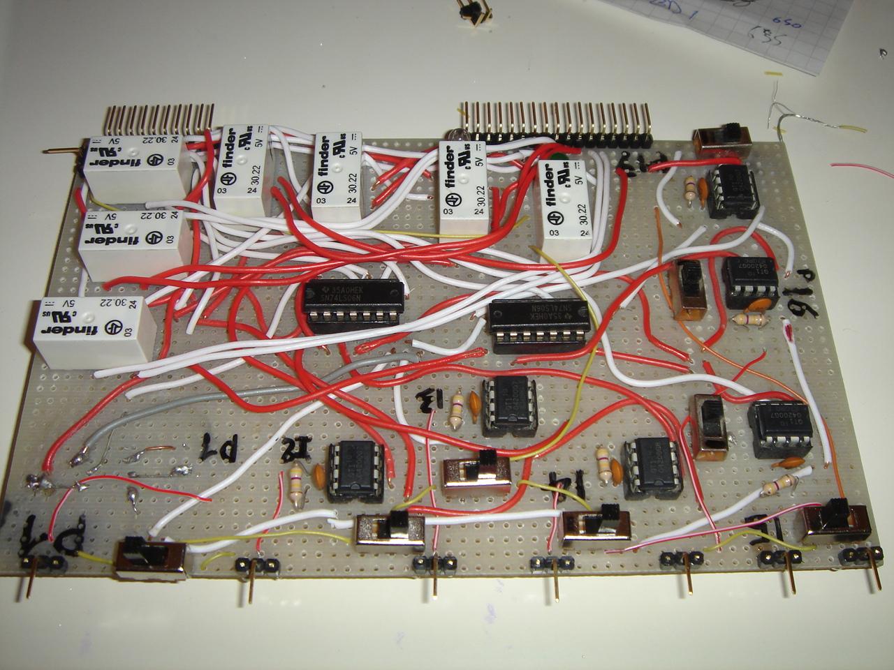
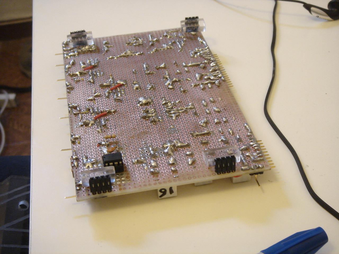
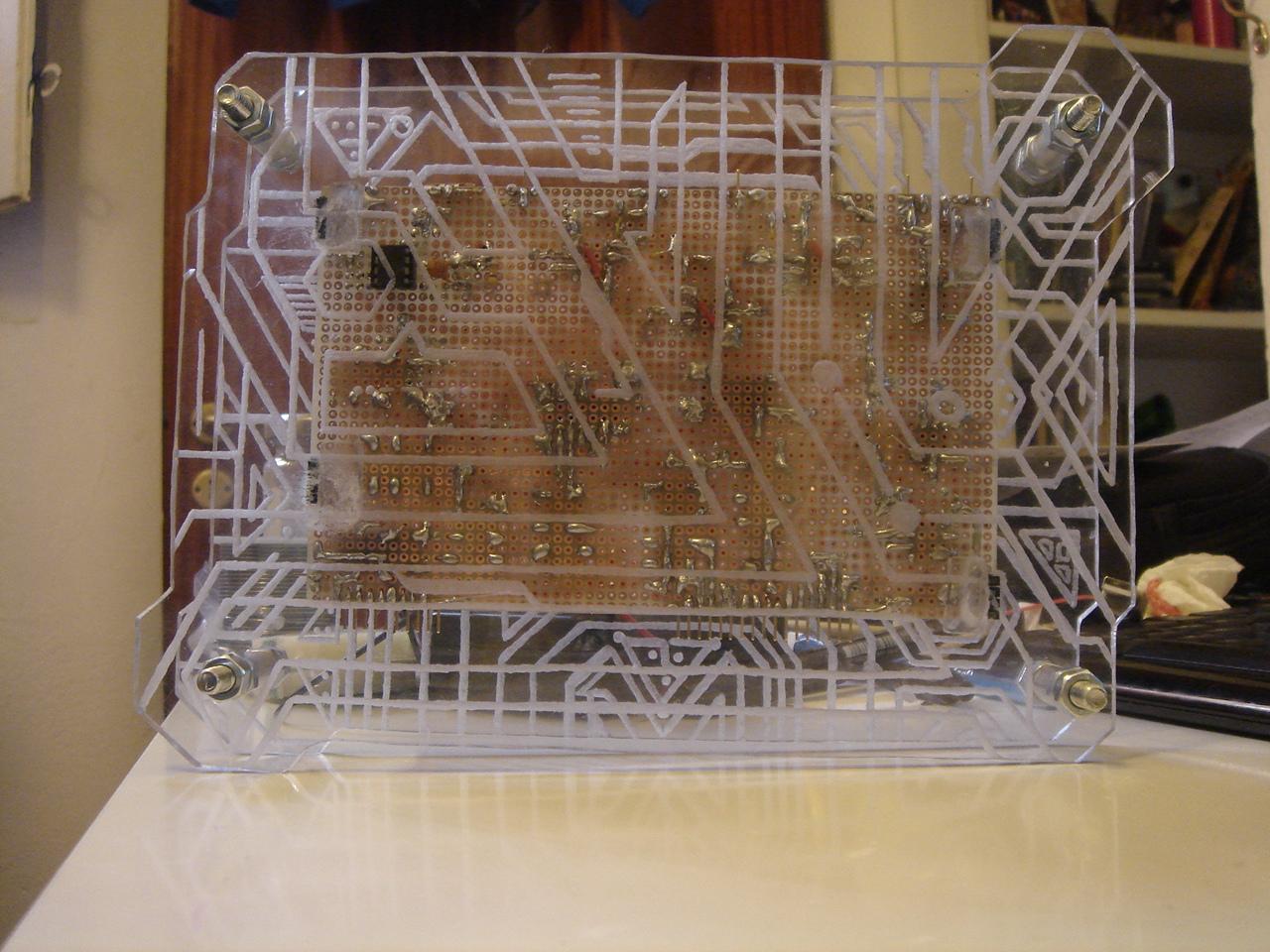
and now I start by soldering the part that manages the feedback LEDs for the sensors:
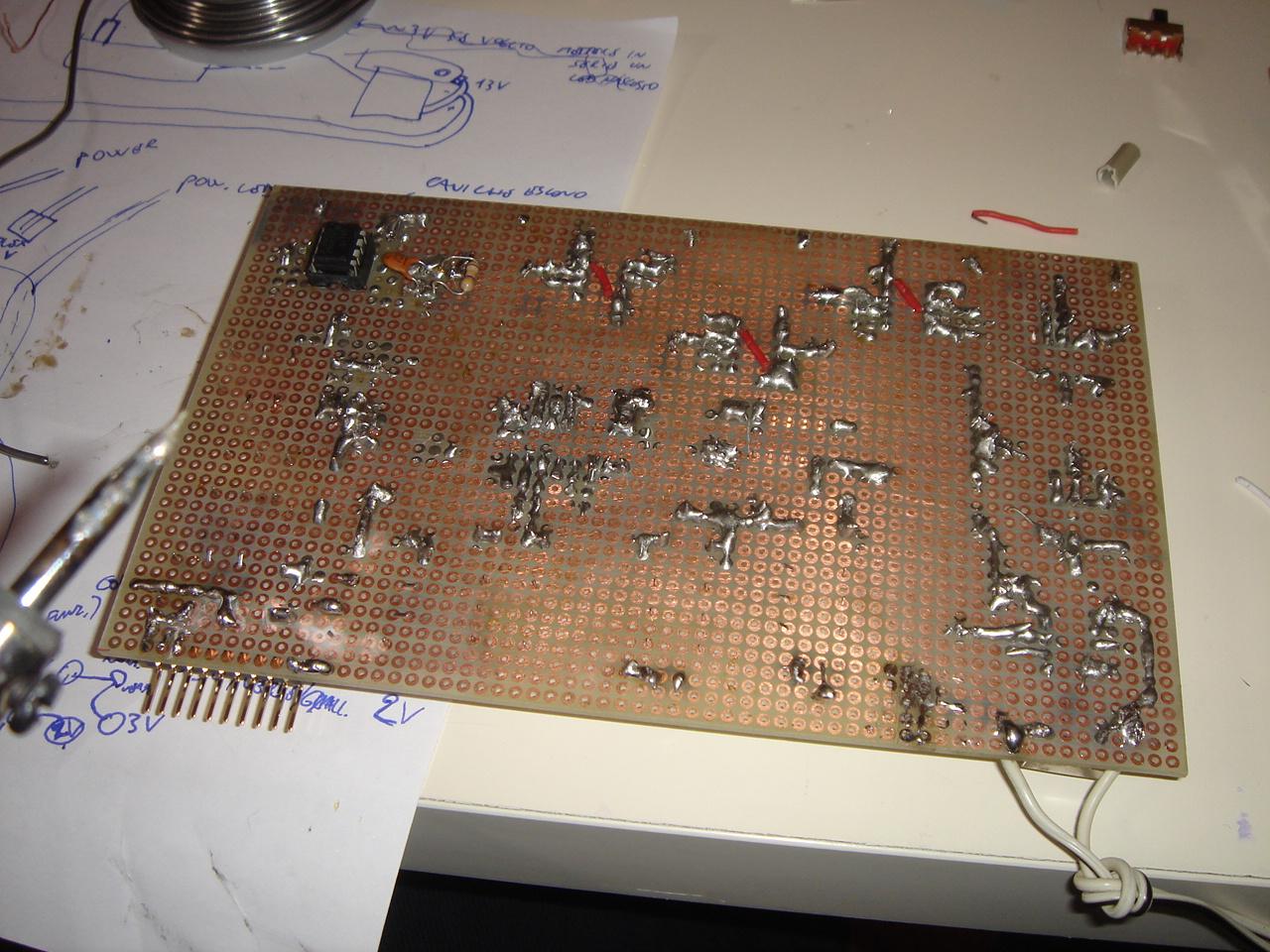
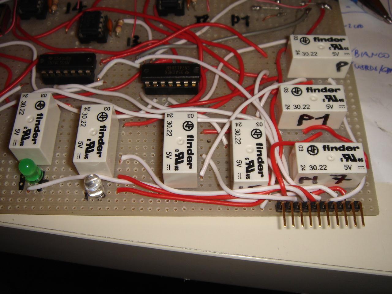
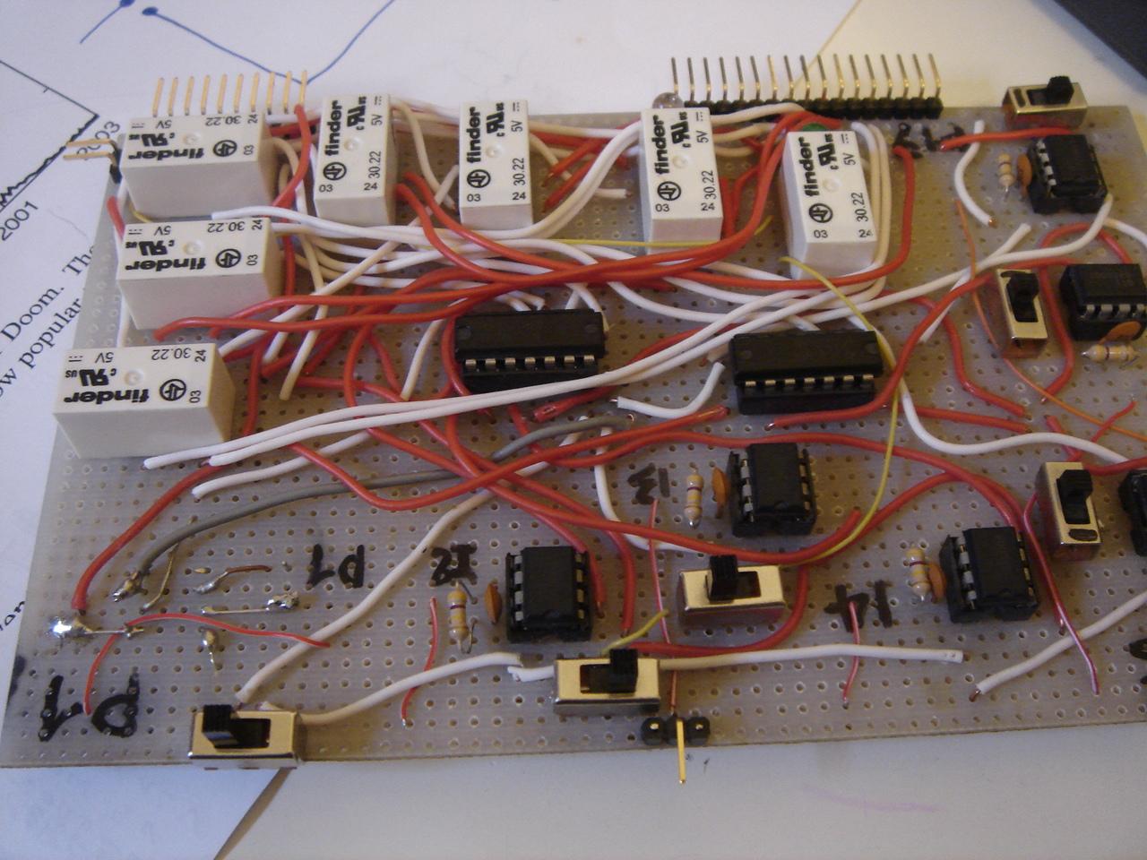
Then, i soldered the contacts socket for all the connections with the devices.
(to reduce the number of cables, I took a 10-wires cable for the feedback LEDs, and a 17-wires cable for the devices, so only two big cables will be connected to the circuit, hiding the fact that the circuit needs 17 connections with the components of the case, and 10 with the feedback LEDs).

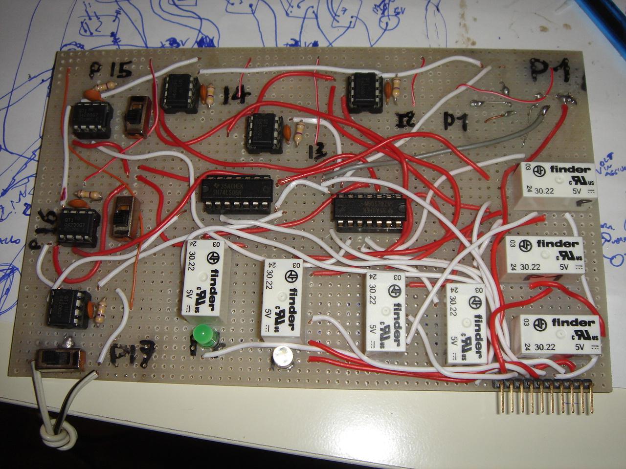
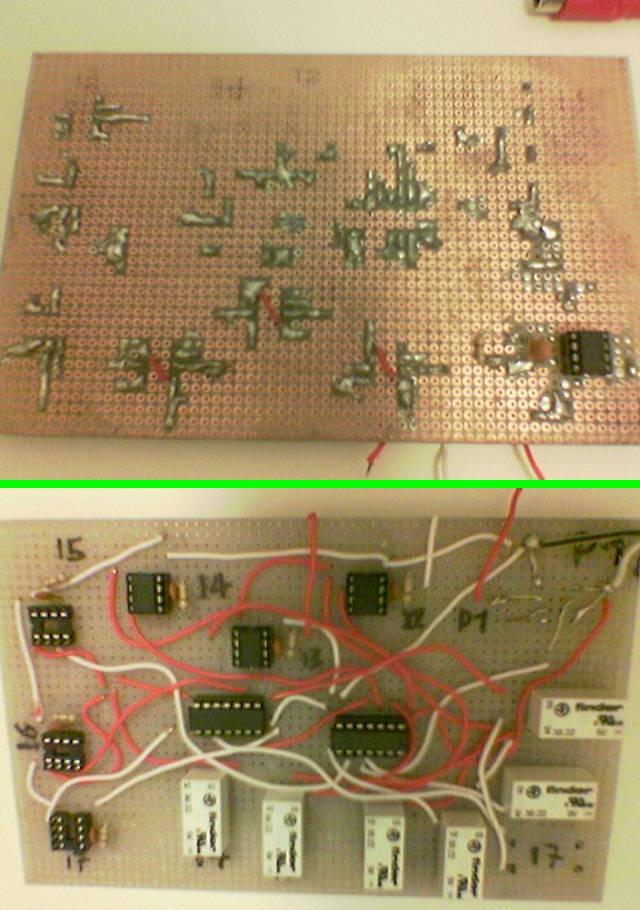
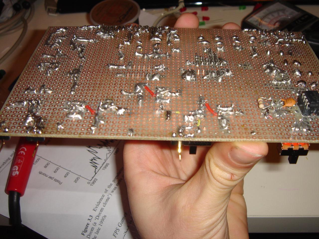
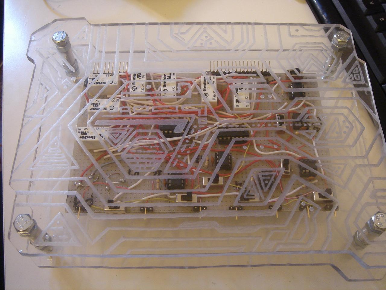
The wires have increased a lot. For a comparison, this was the circuit before this last job:
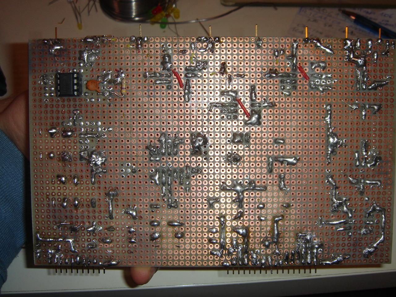
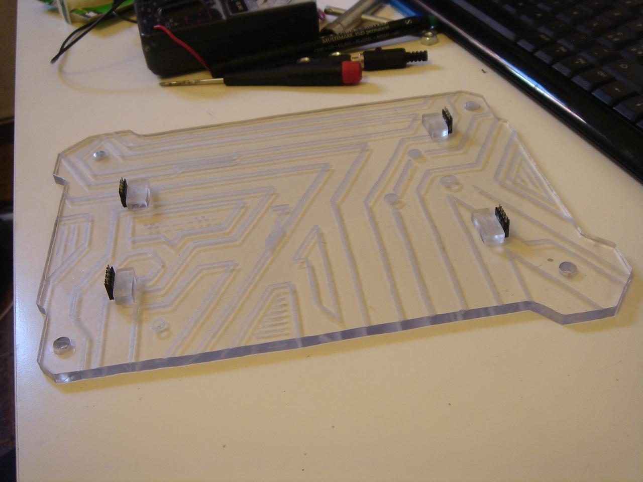
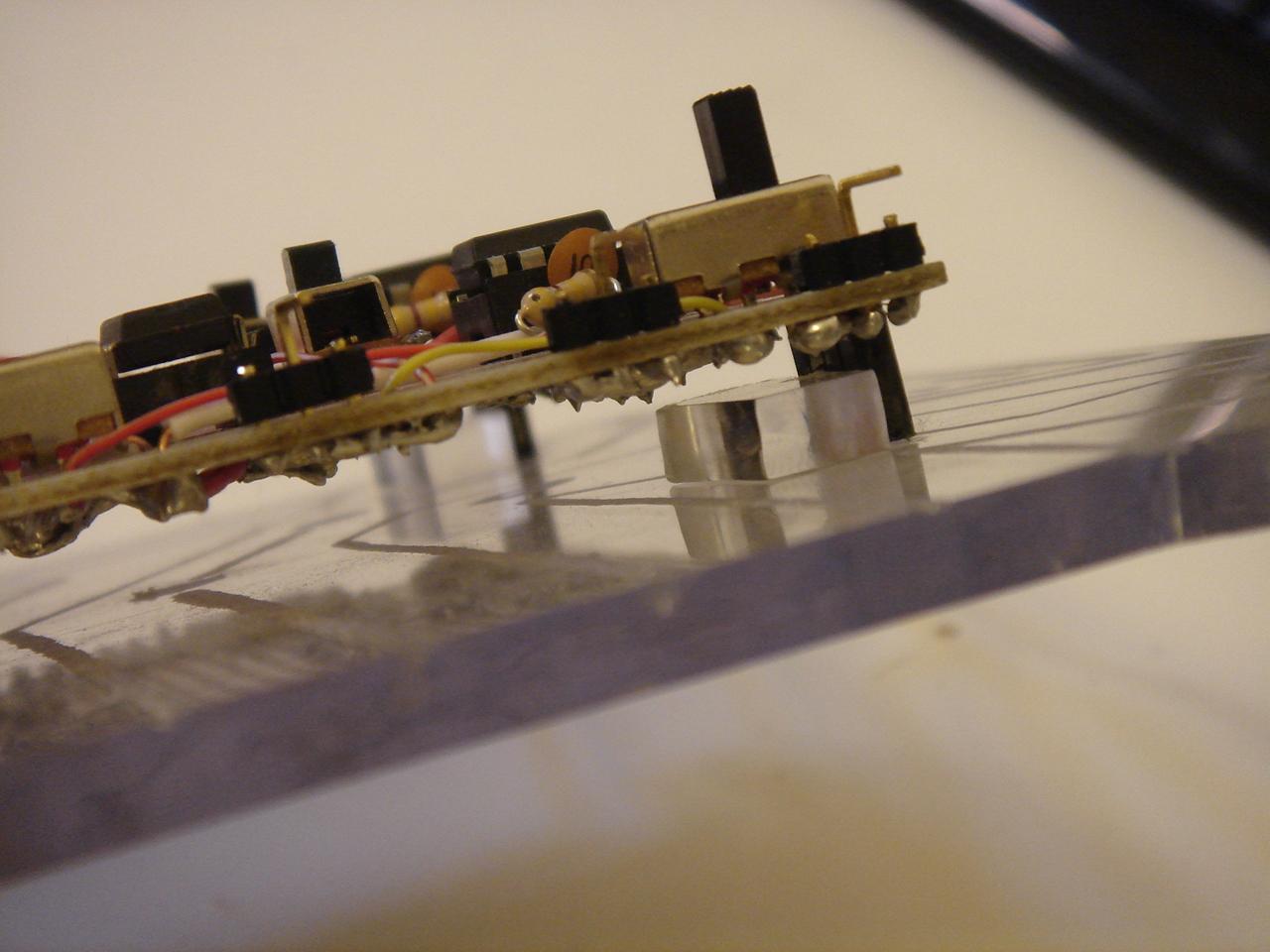
Then I started to solder the single contacts for the touch sensors and for the proximity sensor.
The proximity sensor will be on the left side wall of the case, and detects the proximity of the hand (at 2-3cm of distance) instead of the touch of the finger.
It can be activated and deactivated by one of the touch sensors.
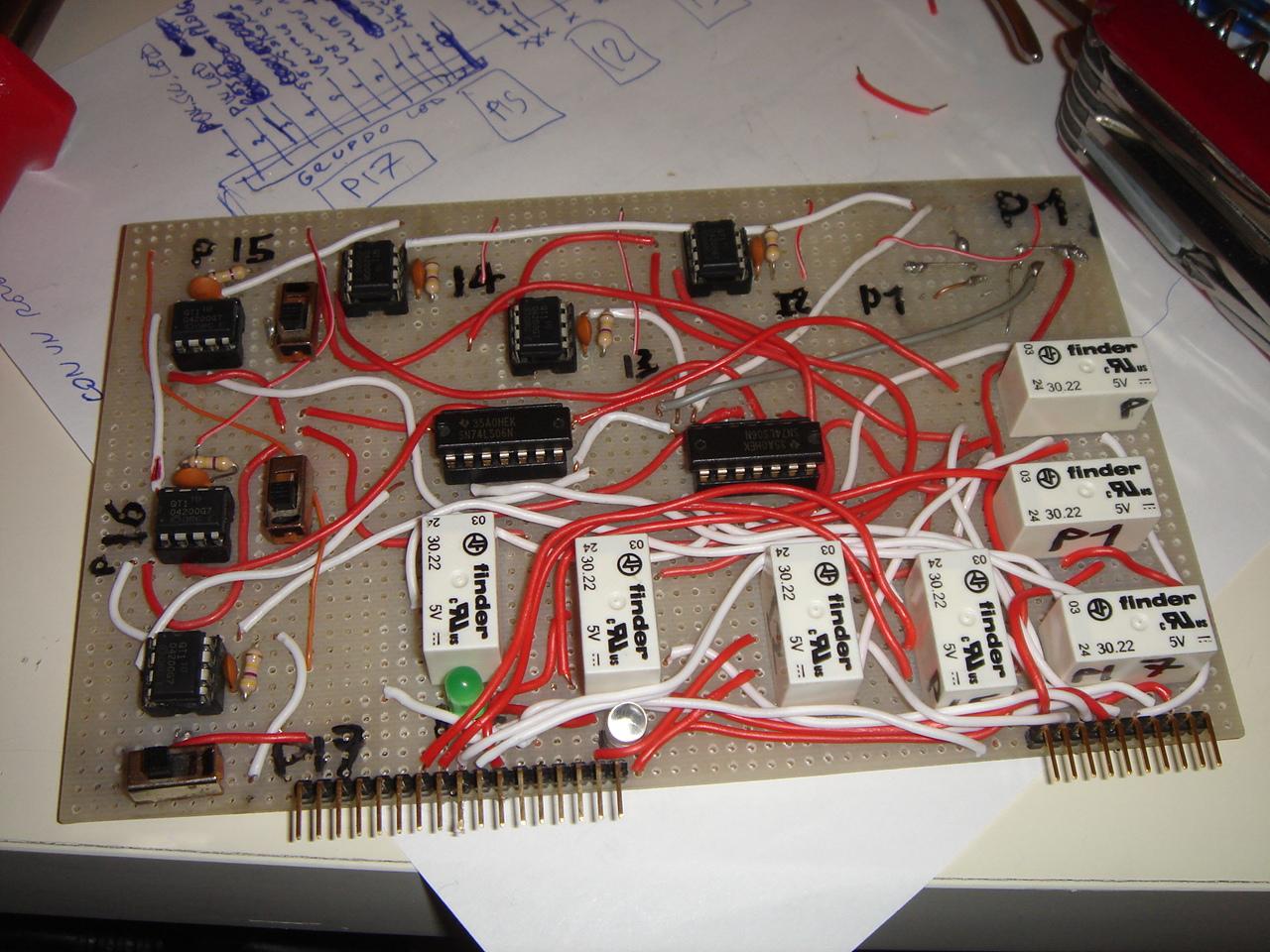
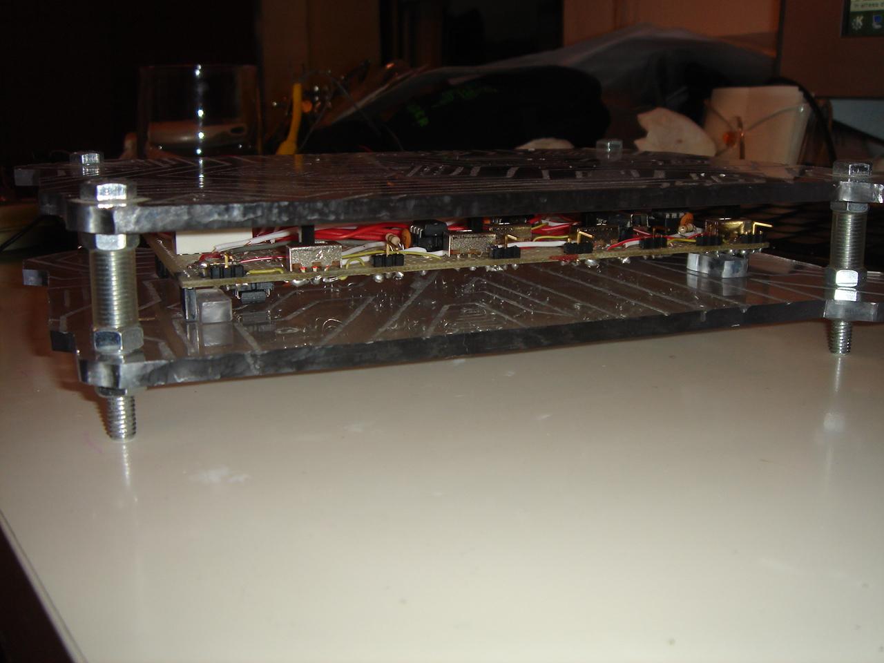
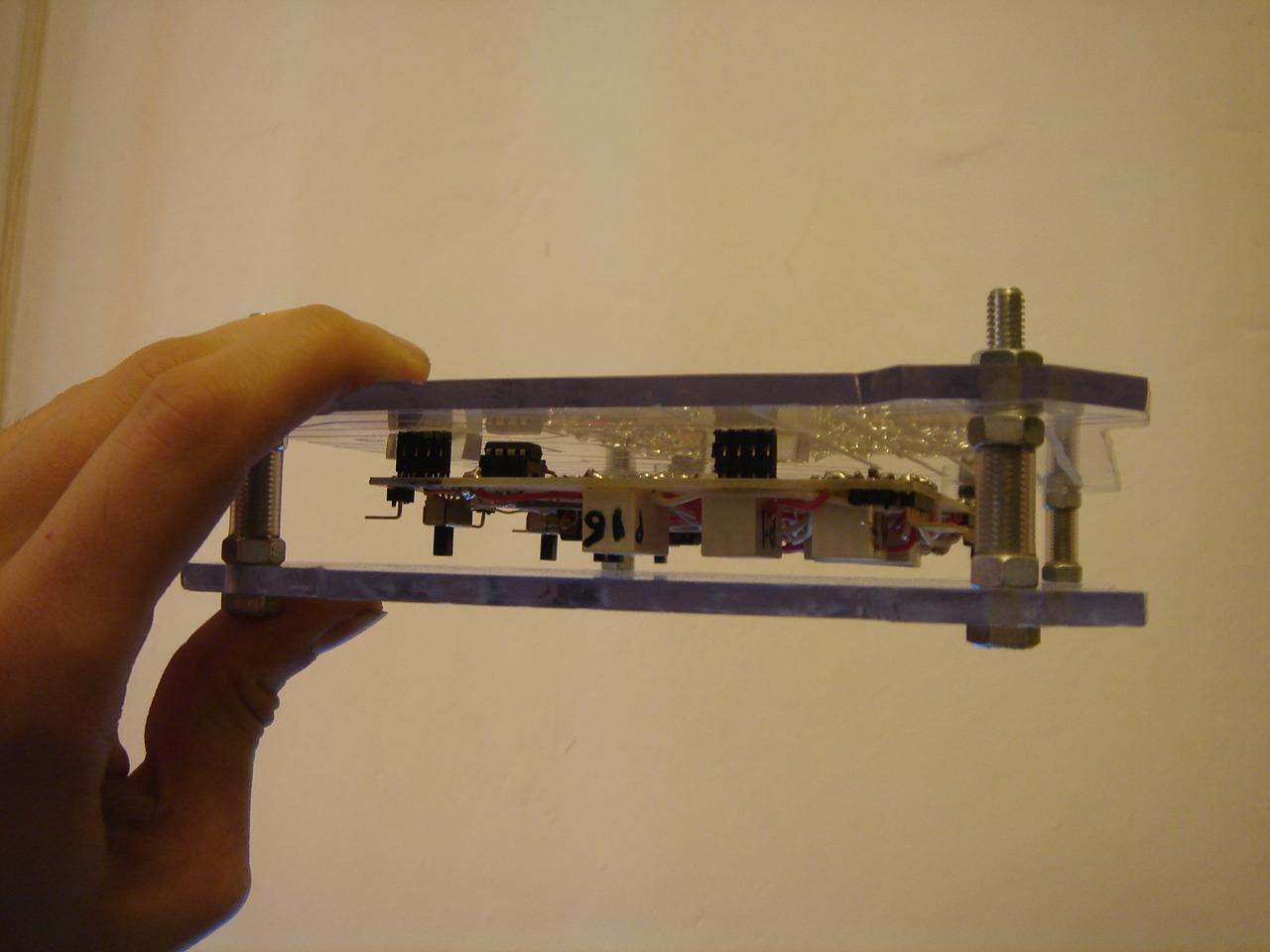
And this is the completed circuit!
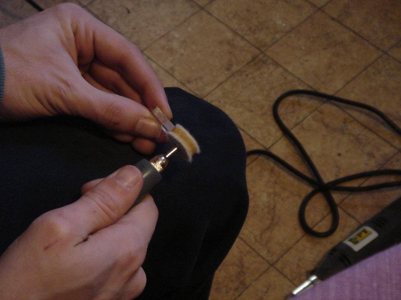
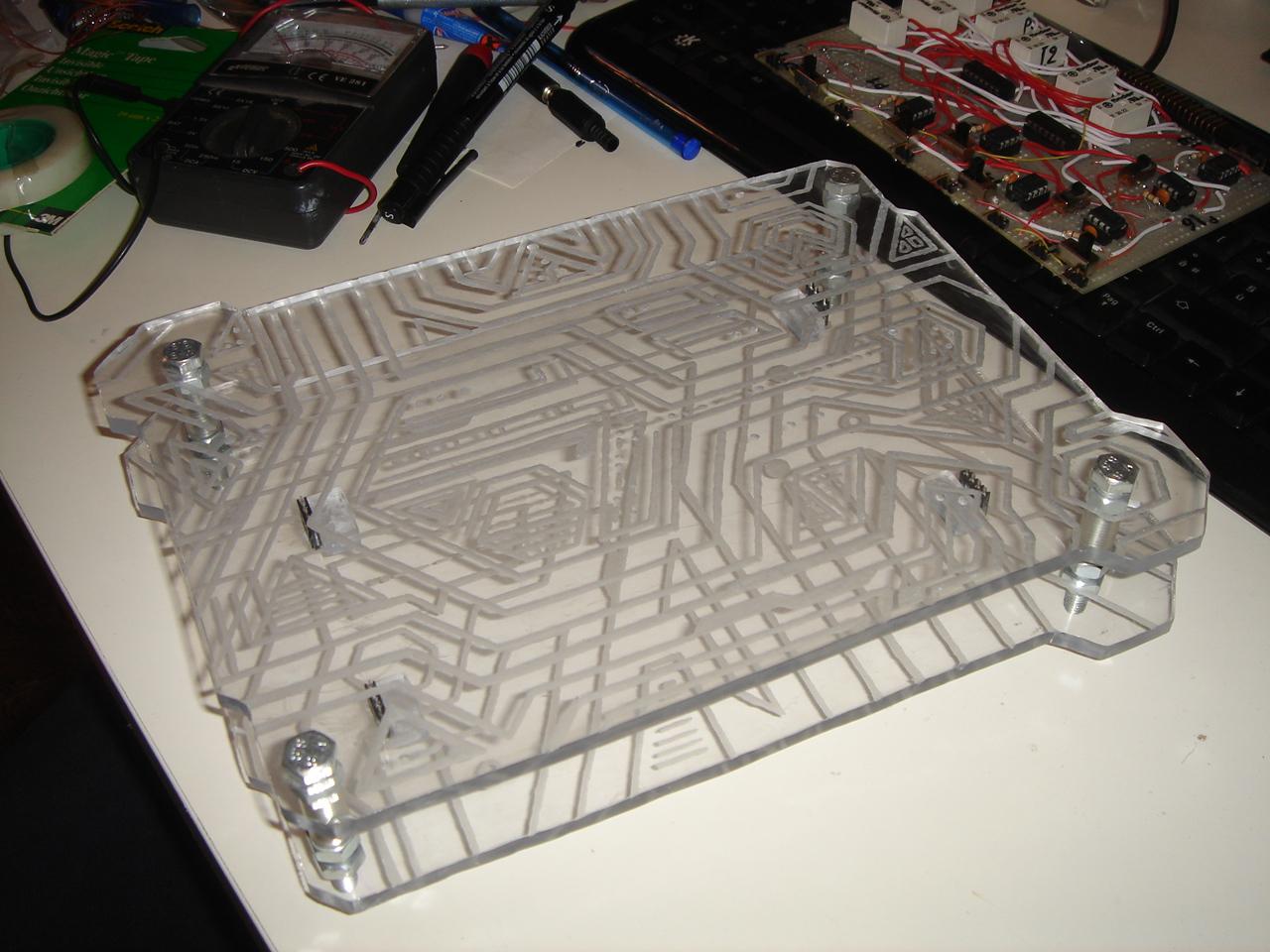
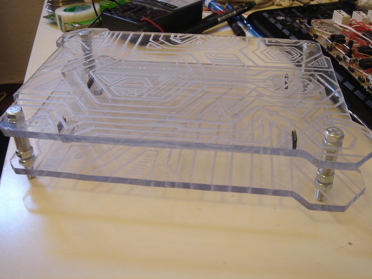
Then I have done a quick job: the supports that keep in place the circuit in the circuit encasing:
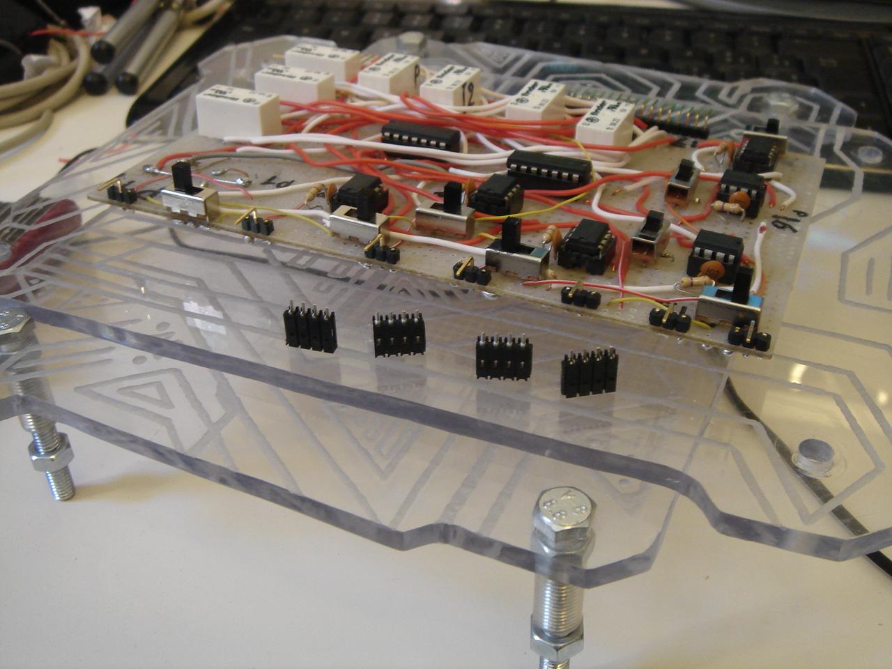

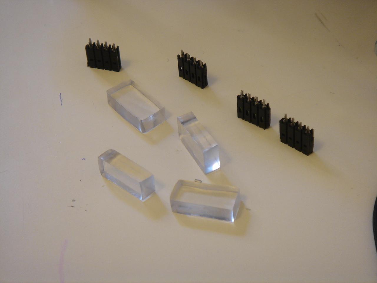
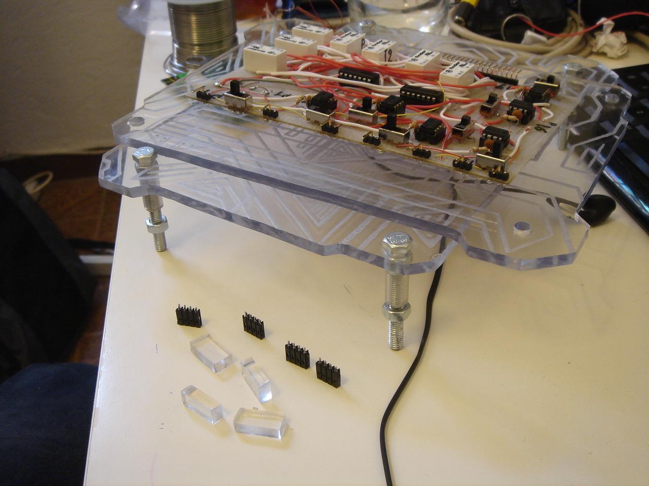
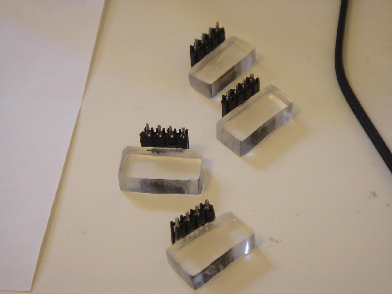
These supports are glued on the base of the encasing:
Now I must proceed with a support for the feedback LEDs, and a cable that connects the circuit with all the devices in the case.