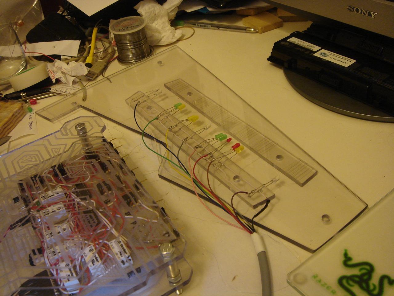
And now, this is a test of the sensors and their LEDs:
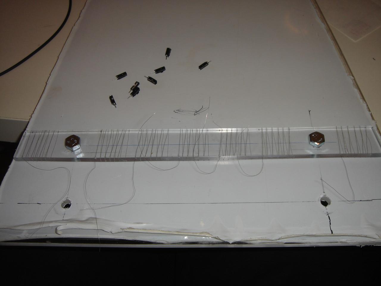
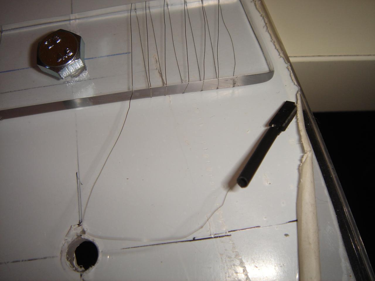
One of the sensor thin wires was broken, and I had to replace it:
I connect all the components of the sensors circuit:
I turn on the circuit, and…
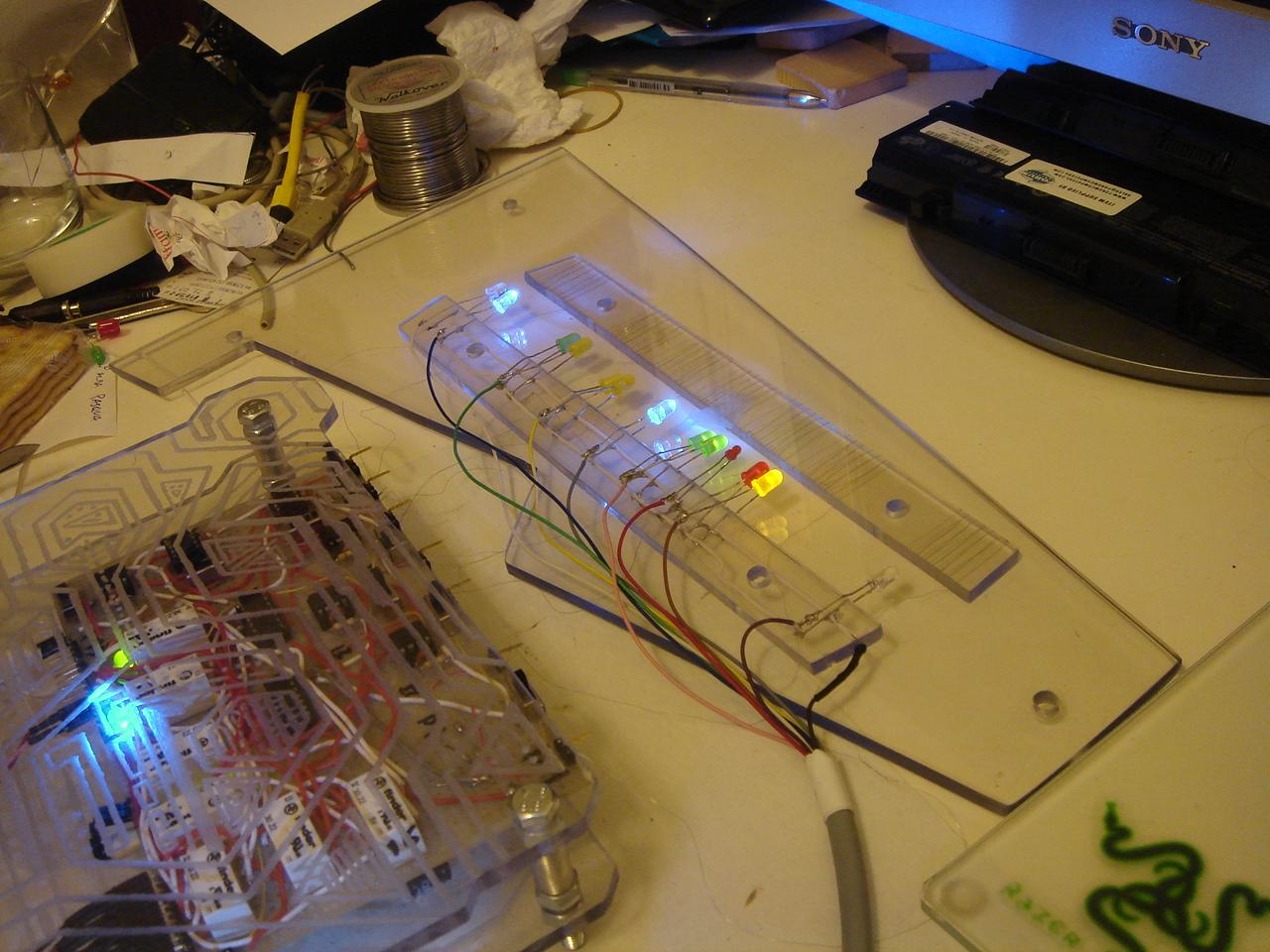
…this is the video of the test!
(note that the sensors bar is below the policarbonate panel, so the sensors detect the fingers at a 5mm distance through the polycarbonate panel)
In order, I press:
– power switch (the white led, only for the press duration. The adjacent blue led is the power led that is always on when the PC is on)
– reset switch (green-yellow leds)
– mysterious device on/off (yellow leds)
– proximity sensor on/off (blue led)
– 5/12v fans speed (red led for 12v or green leds for 5v)
– audio on/off (red-yellow leds)
– lighting on/off (white led)
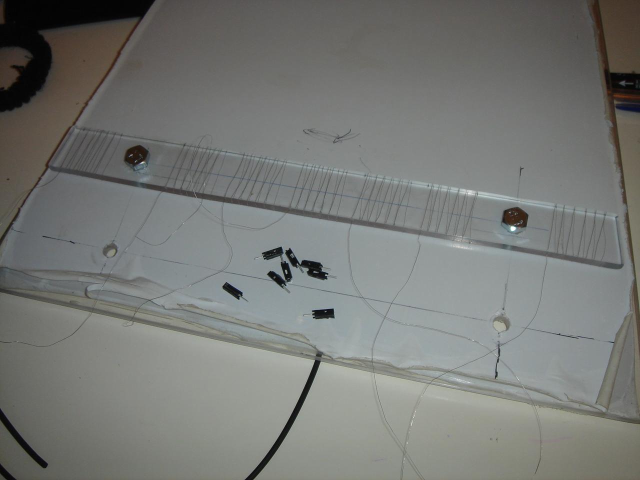
I soldered the single connectors to the sensors thin wires: it’s something I have not done until now because I was too scared to break them, these wires are very fragile…
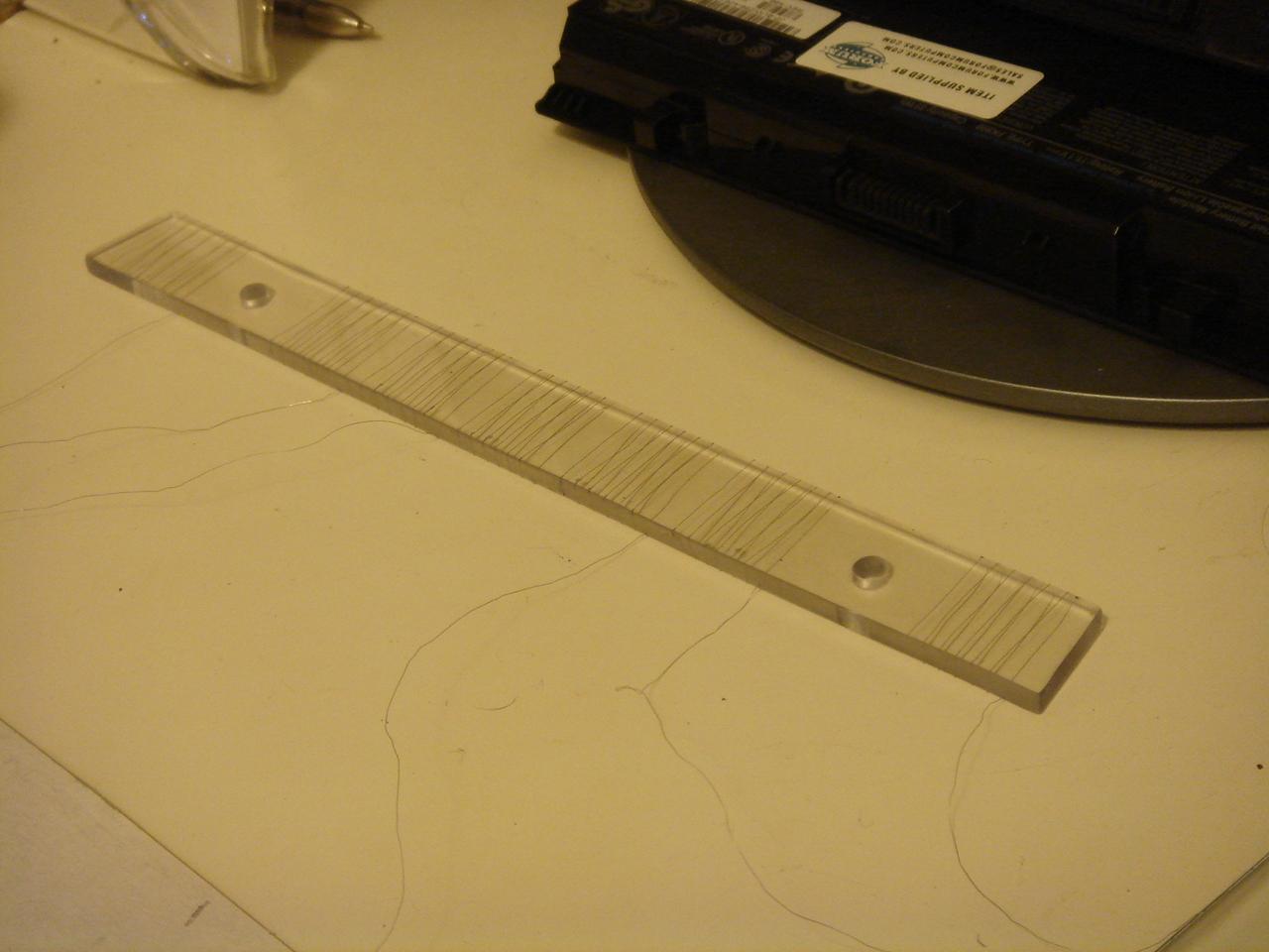
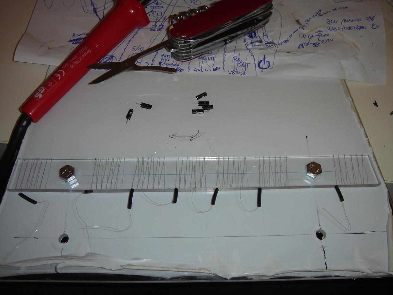
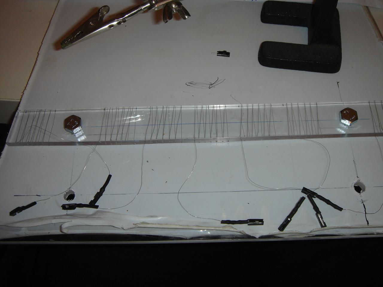
the sensors before this operation:
I cut the sensor wires at the correct length:
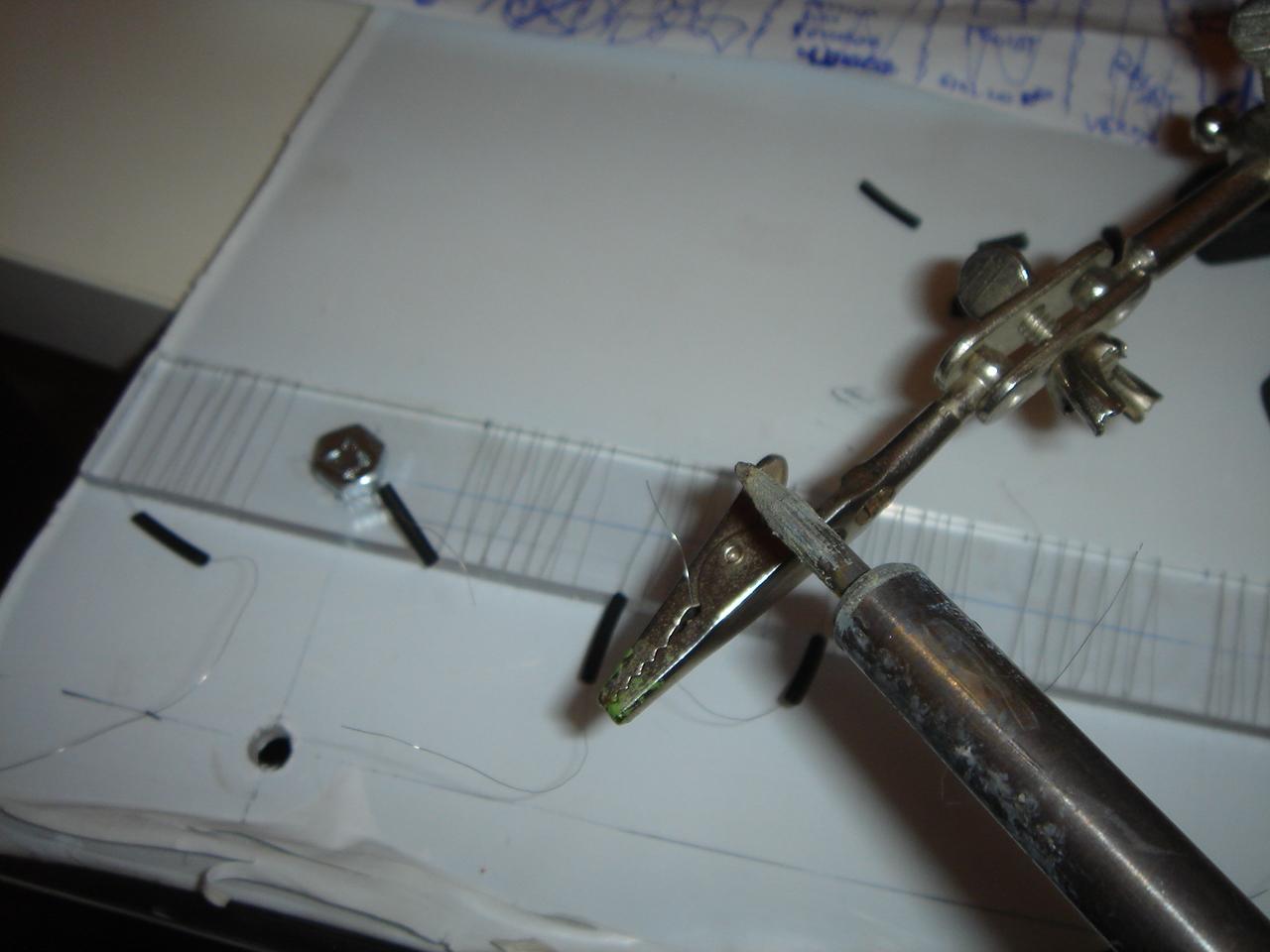
I start soldering the wires to the connectors:
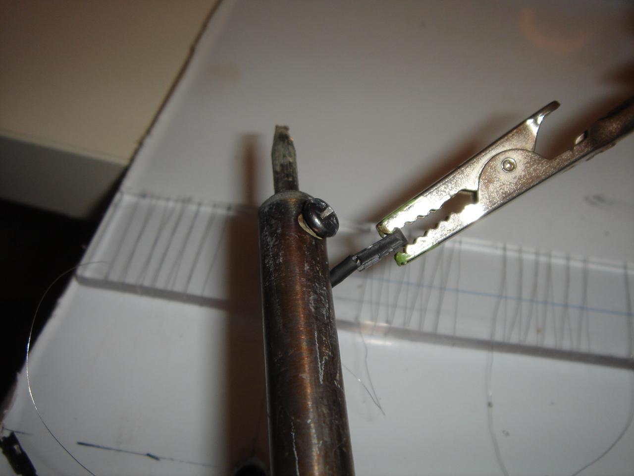
…and done, luckily without any broken wire:

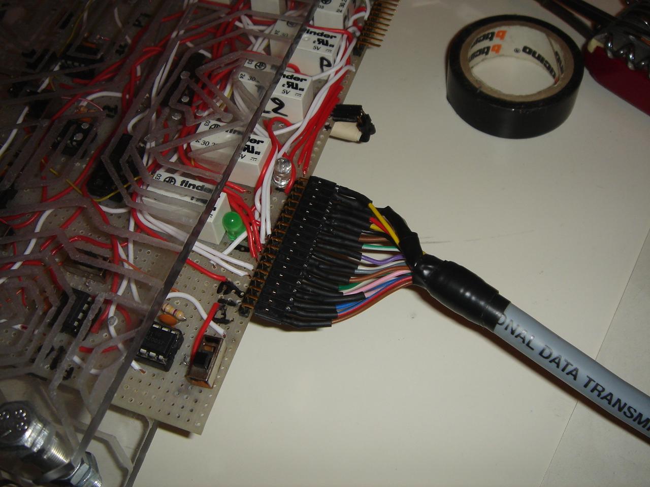
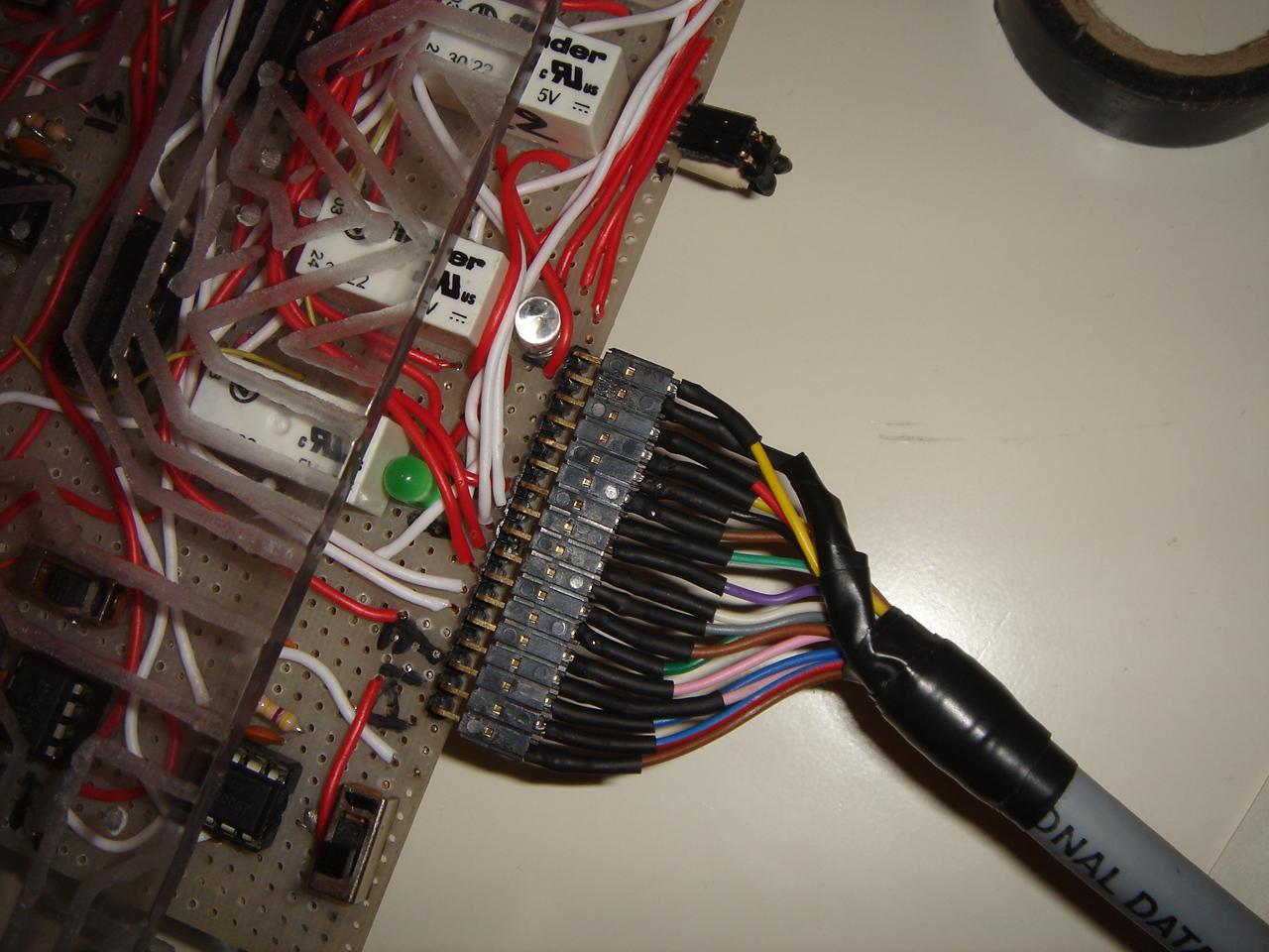
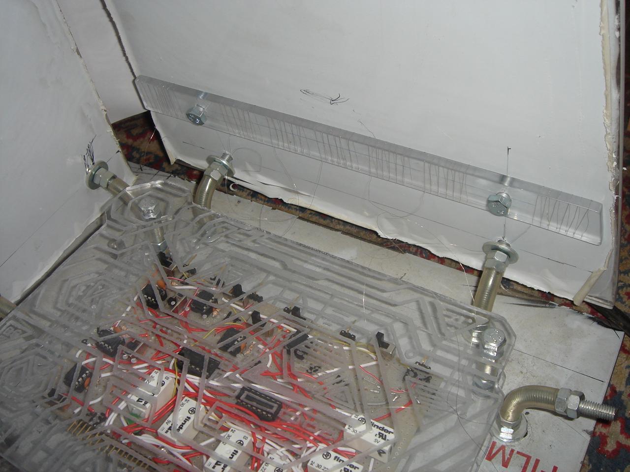
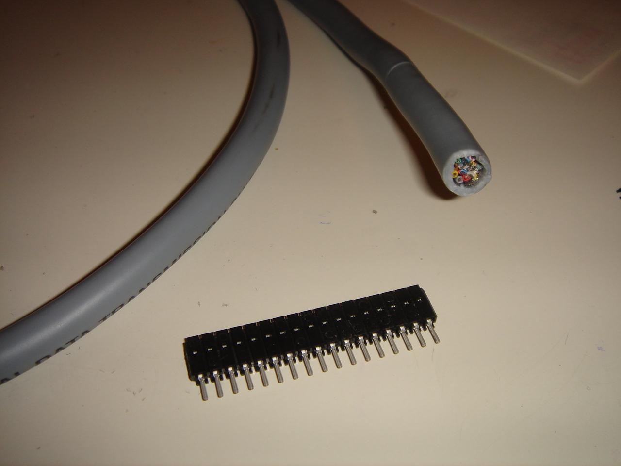
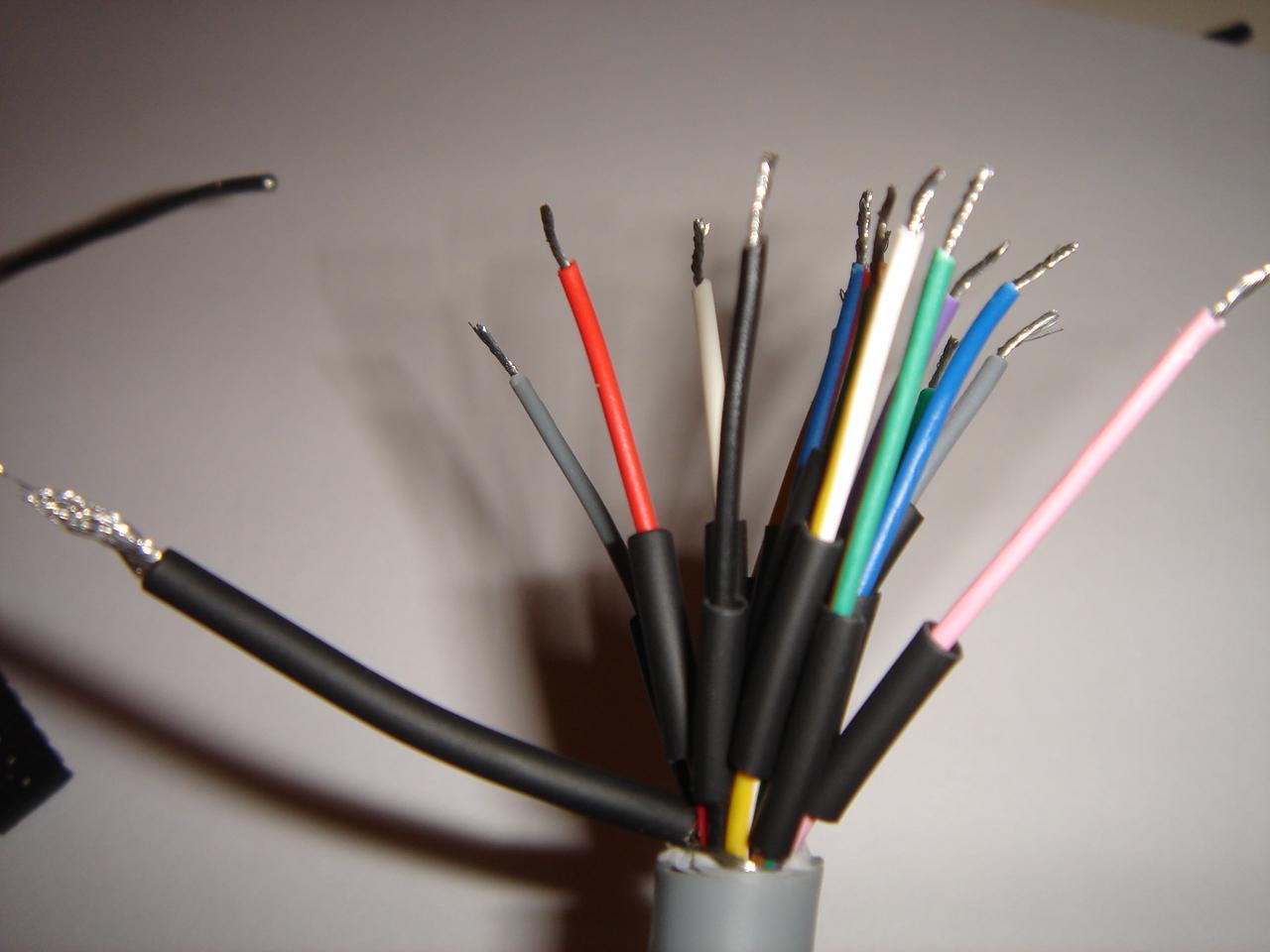
Then I soldered the 16-pole cable to the circuit connector (the bigger black wire in the pic is the metallic shielding of the cable, which I use as another wire because I needed 17 wires and not 16):
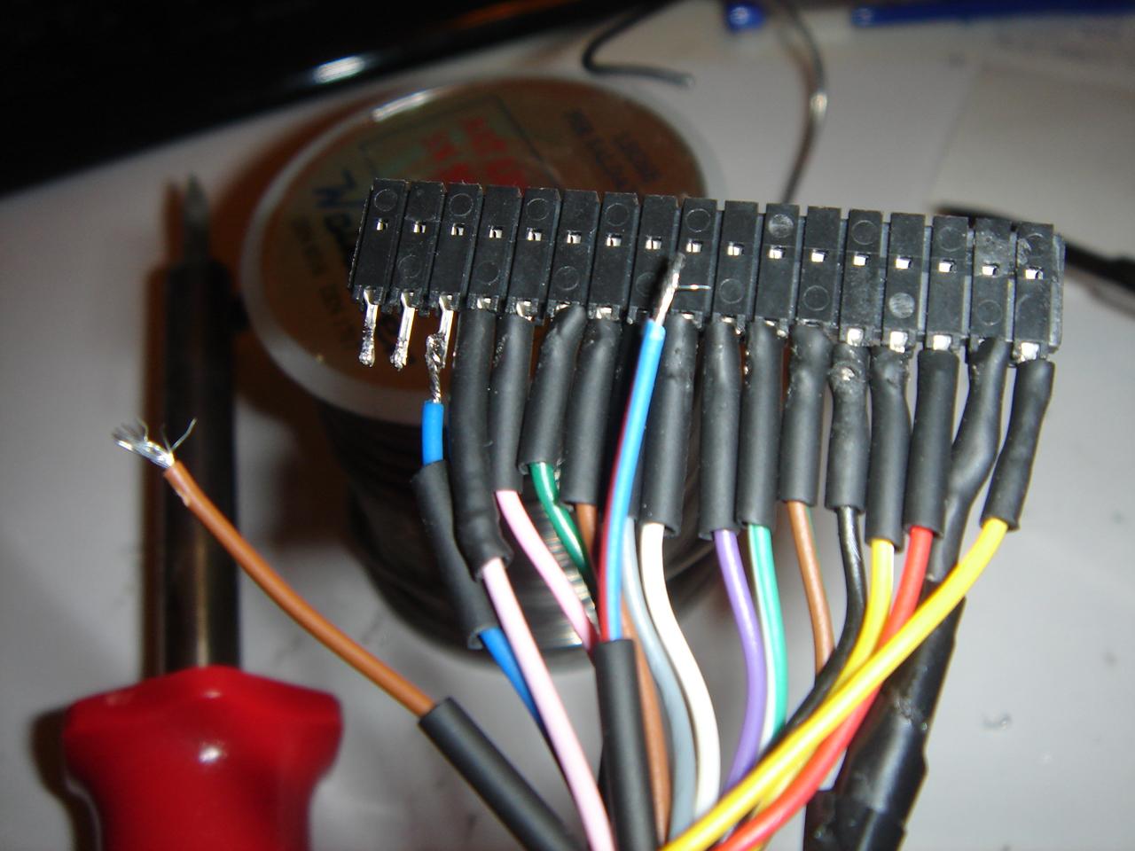
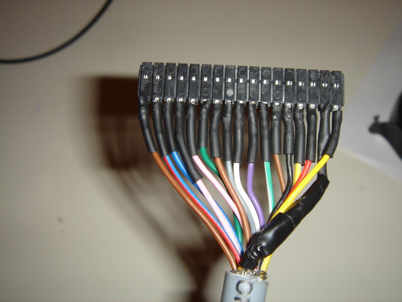
And this is the cable connected to the circuit: