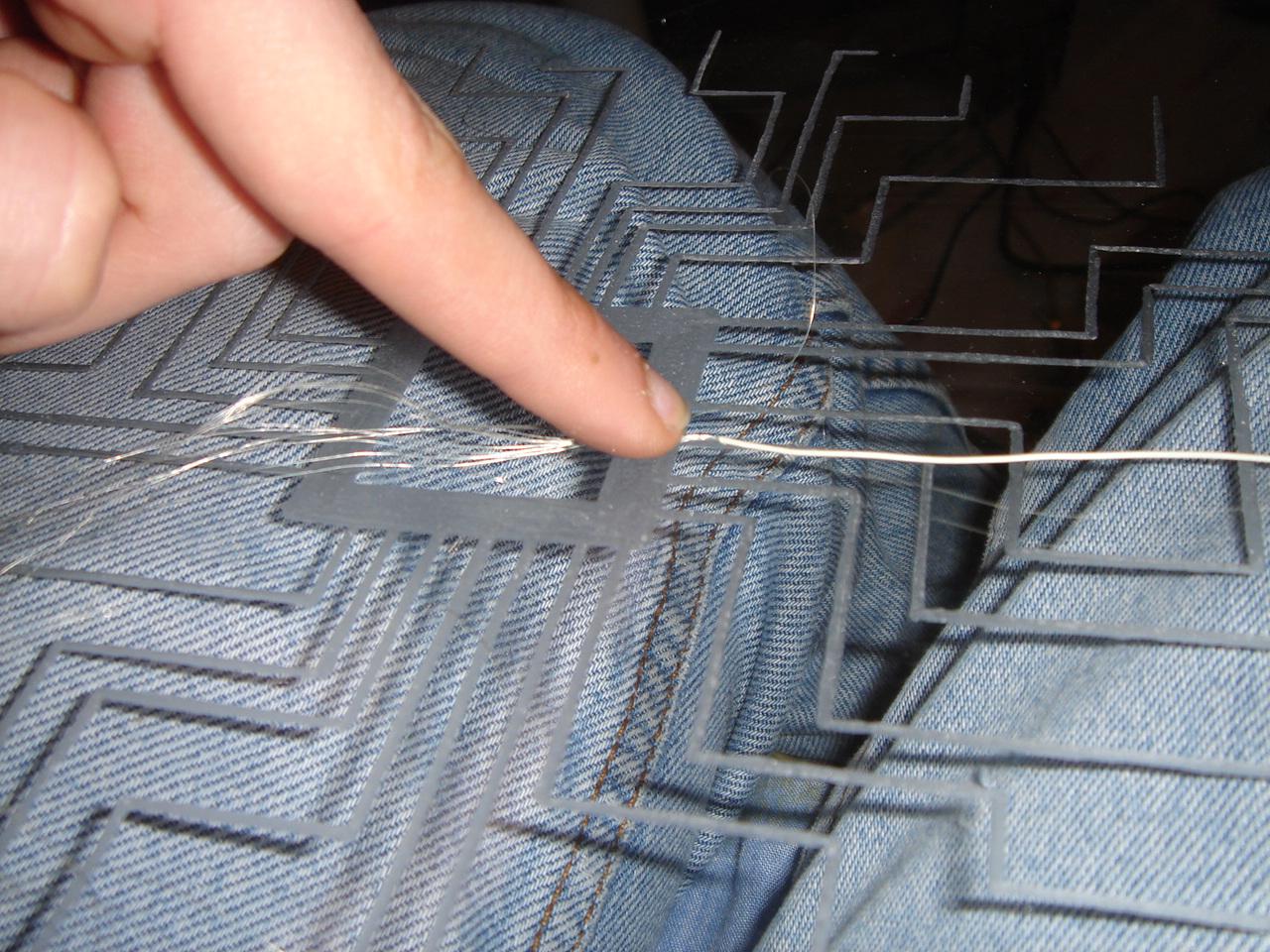
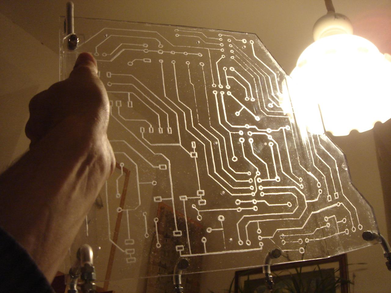
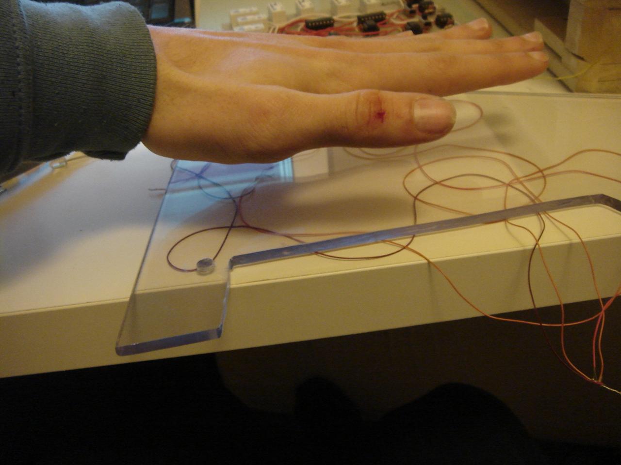
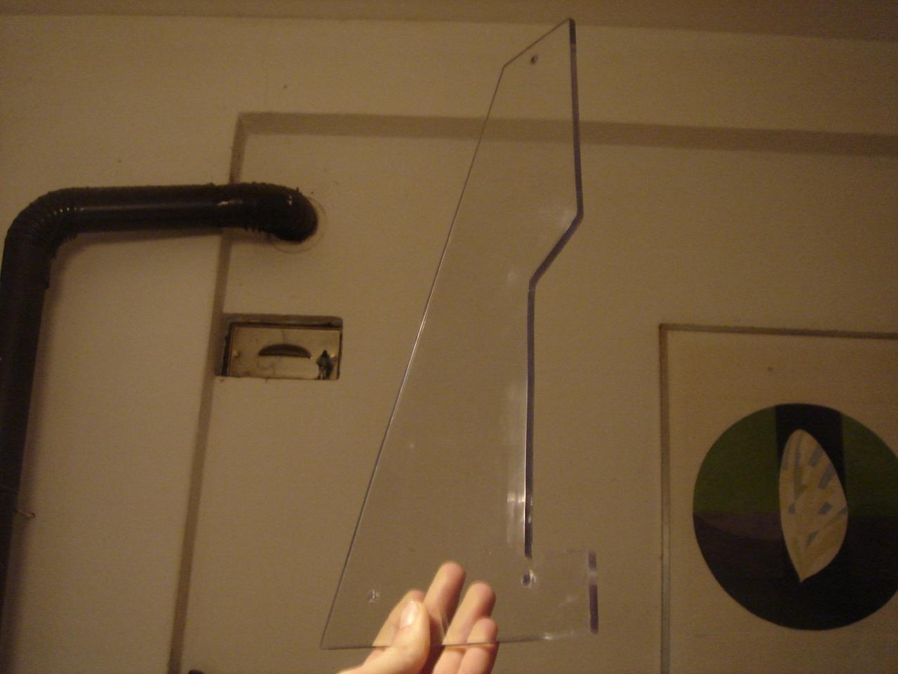
…and finally this is a test of the proximity sensor 😀 (I’m not touching the panel, I’m just putting my hand at a distance of 1-2 cm from the panel):
Monthly Archives: July 2018
making the actual proximity sensor
I finished the proximity sensor, it was a rather long and delicate job (it took at least 4-5 hours).
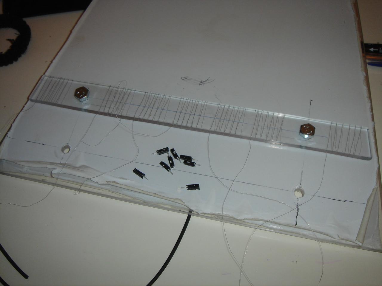
The job was to somehow fix a set of thin wires like the ones I used for the small sensors, behind each line engraved on the panel.
At first I thought to glue the wires, but despite a very solid fixing, I realized immediately that using any kind of glue without ruining the engraving was almost impossible, so I tried another method: I used very thin pieces (thin as the engraved lines) of transparent tape, which hold in place the thin metal wire behind each engraving line.
The pieces of tape were less dangerous than the glue, but it took a lot of time to fix them all!
Anyway these are the pics of the job.
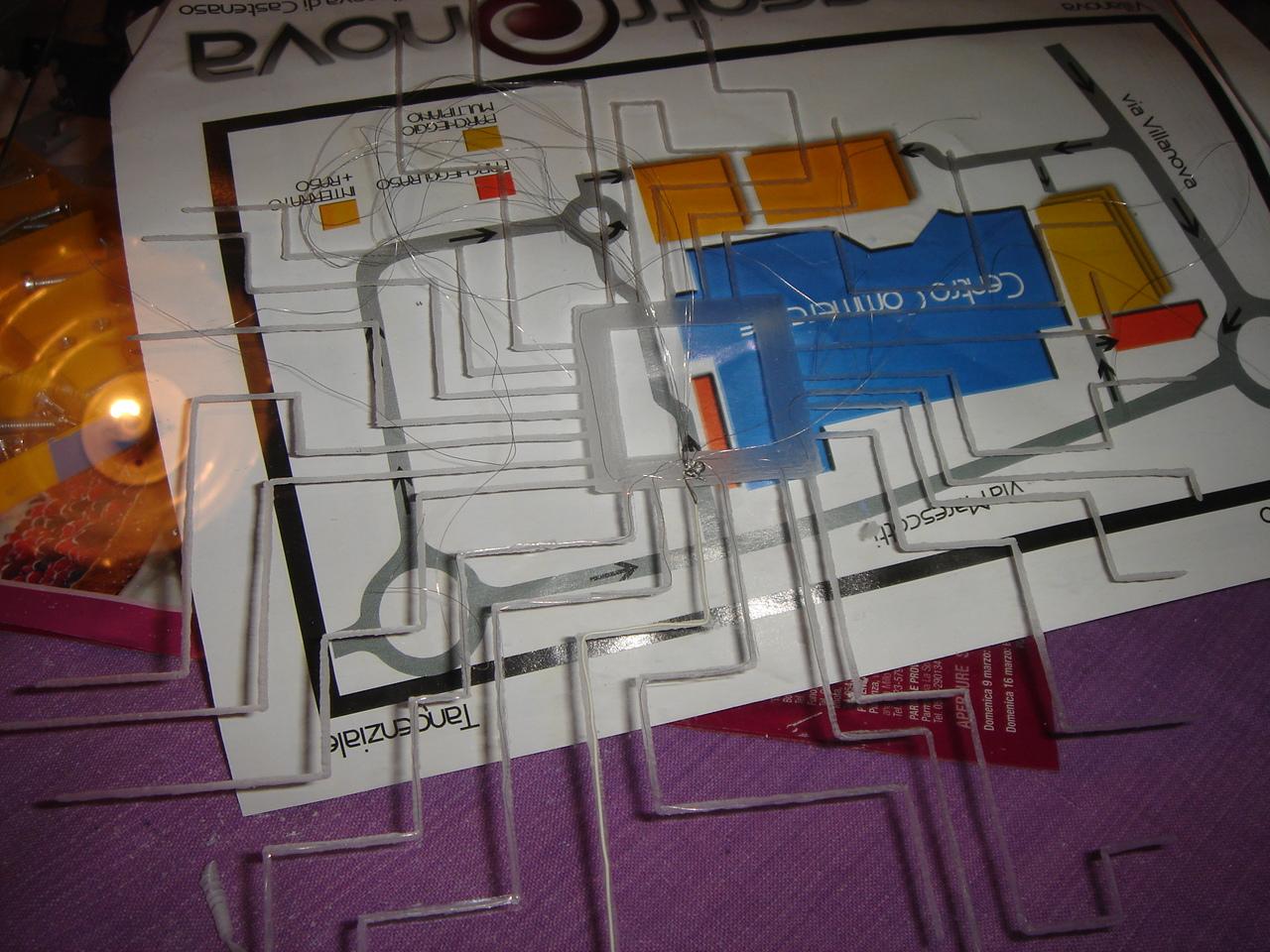
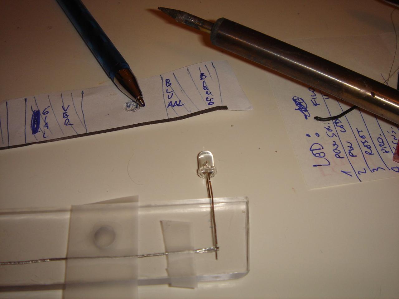
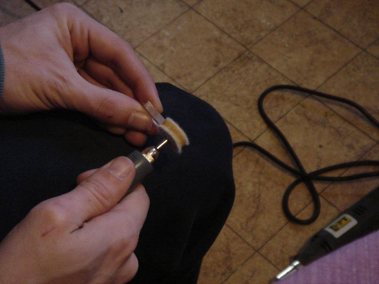
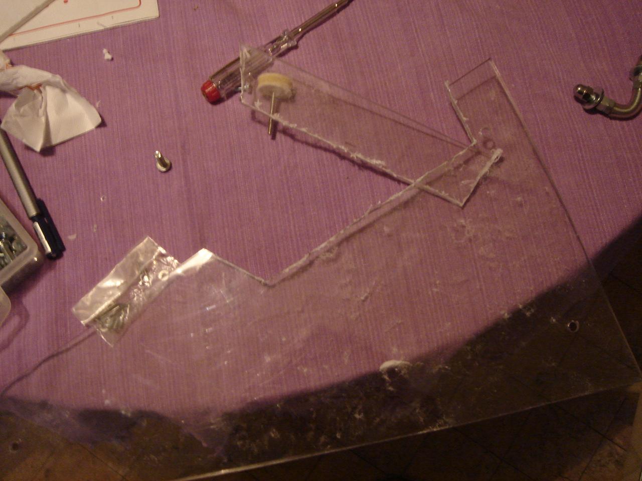
The first try with the glue and a needle:
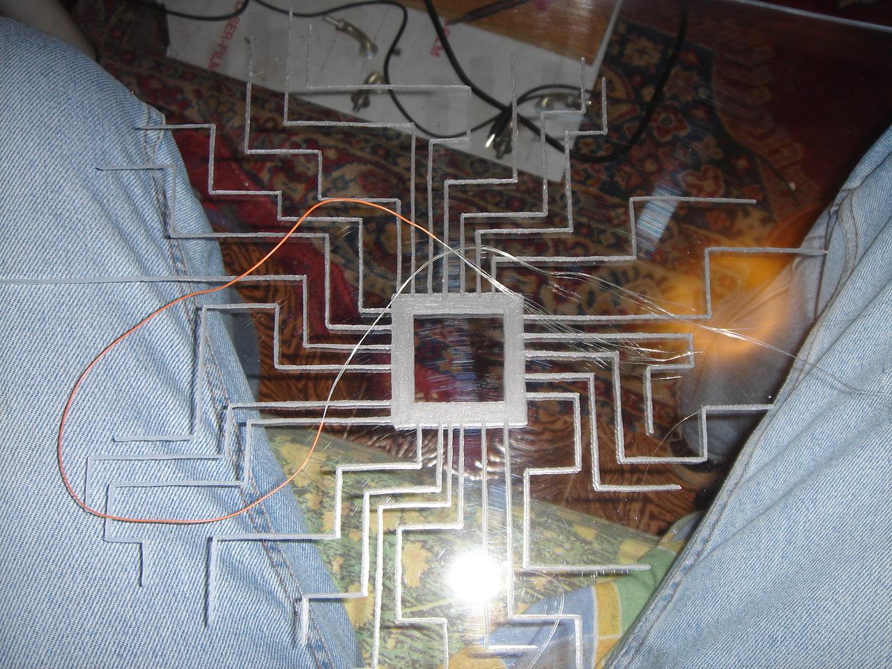
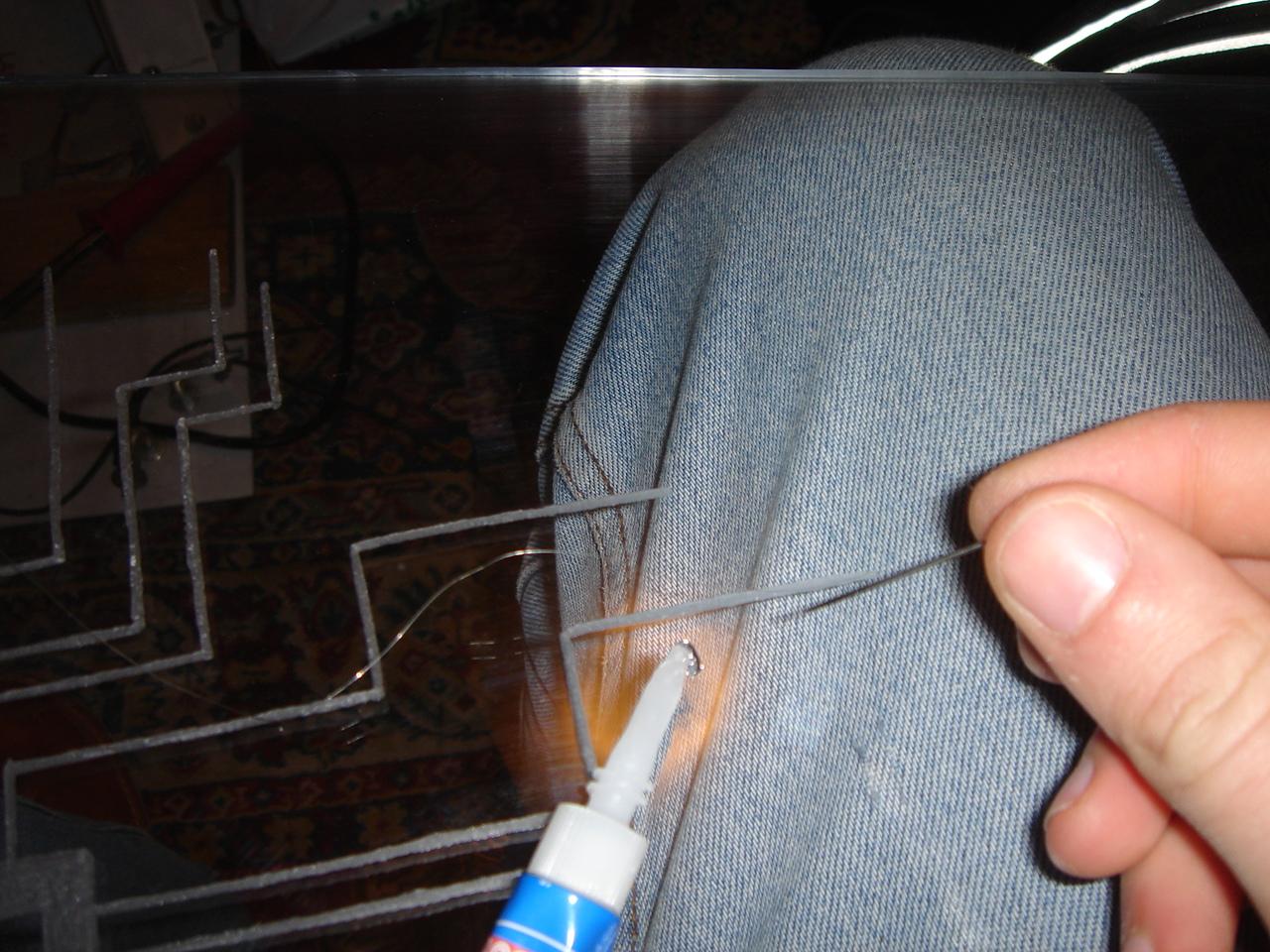
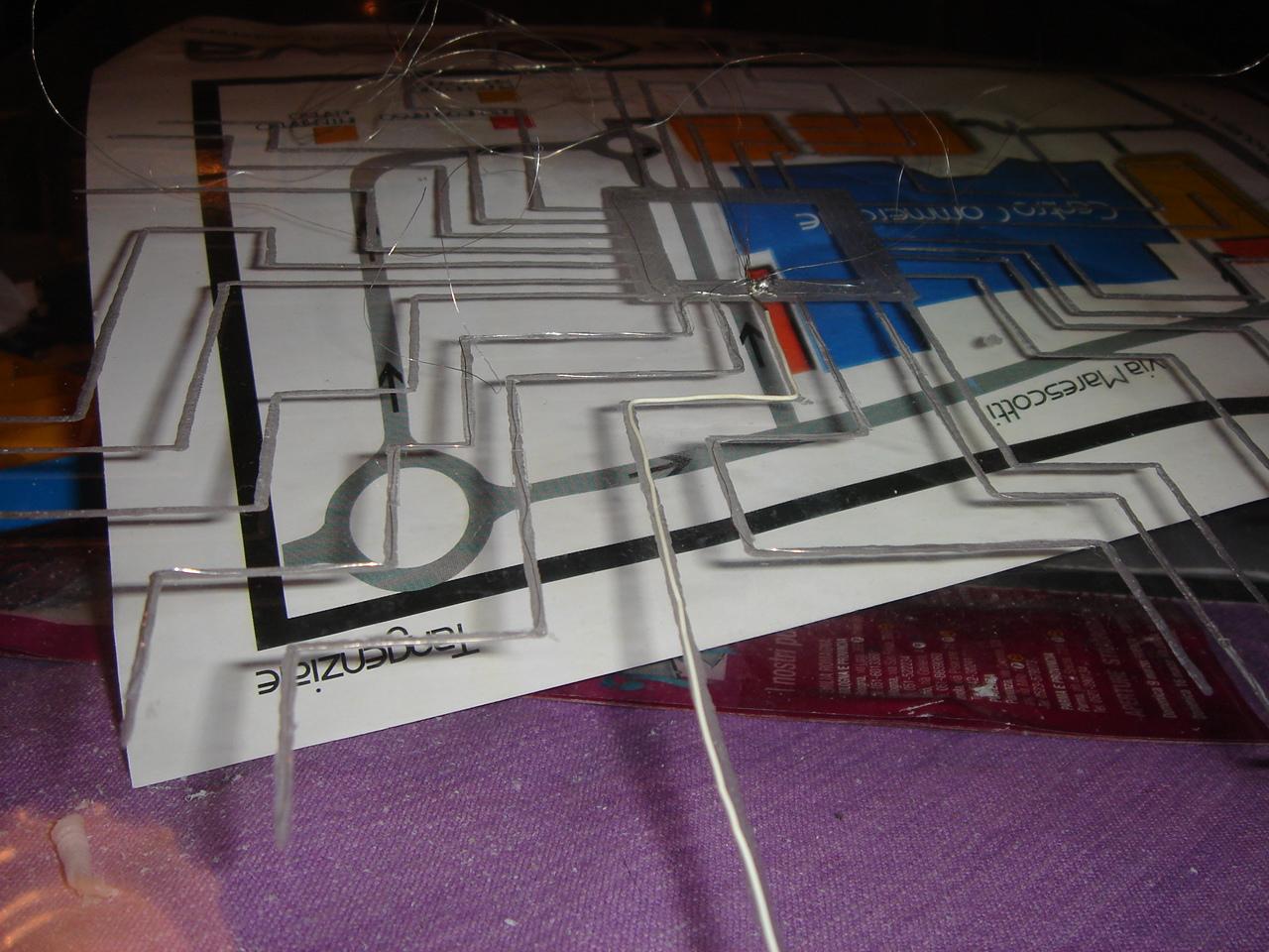
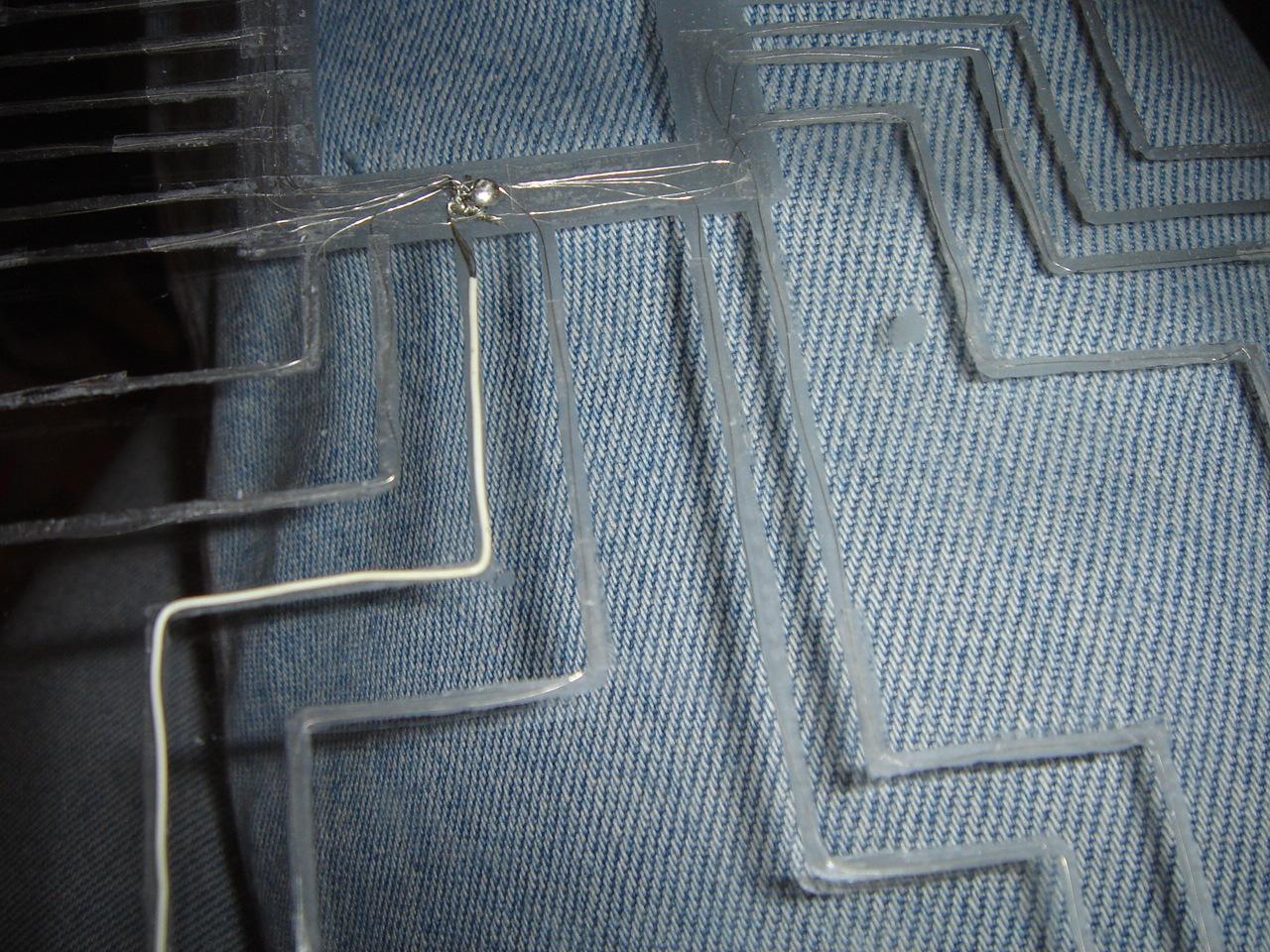
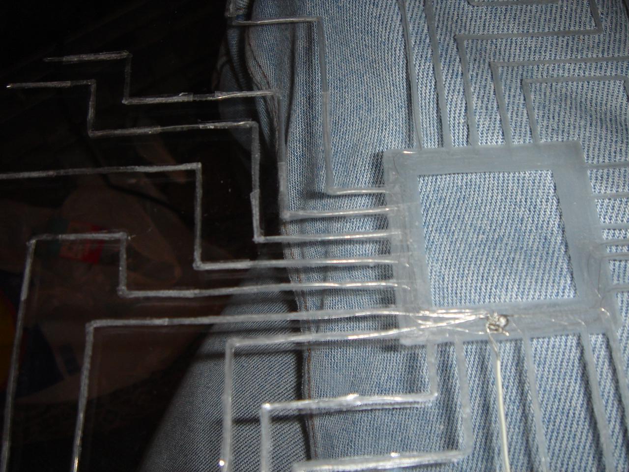
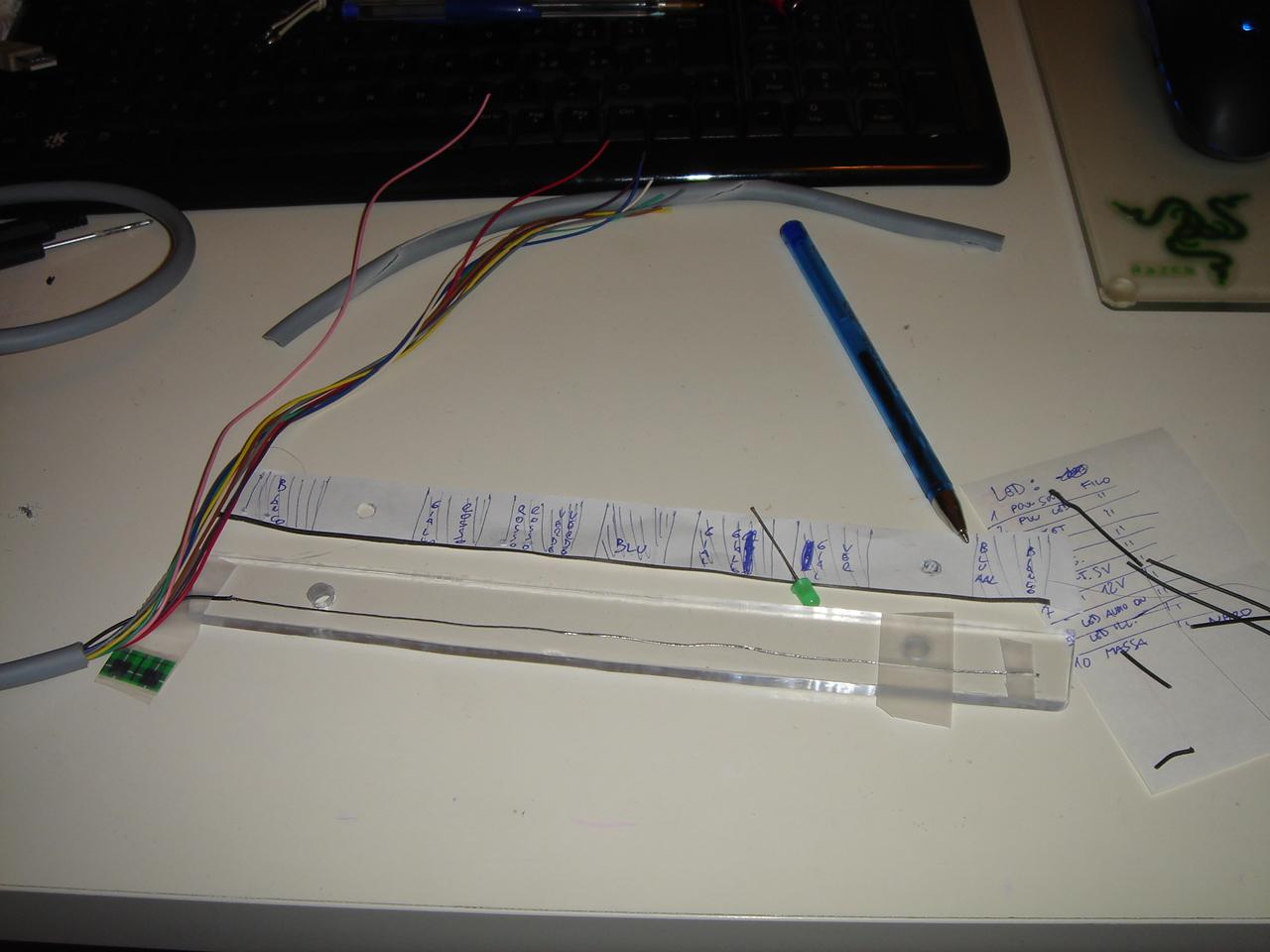
Here I glue the big wire that connects the circuit with all the thin wires of the sensor:
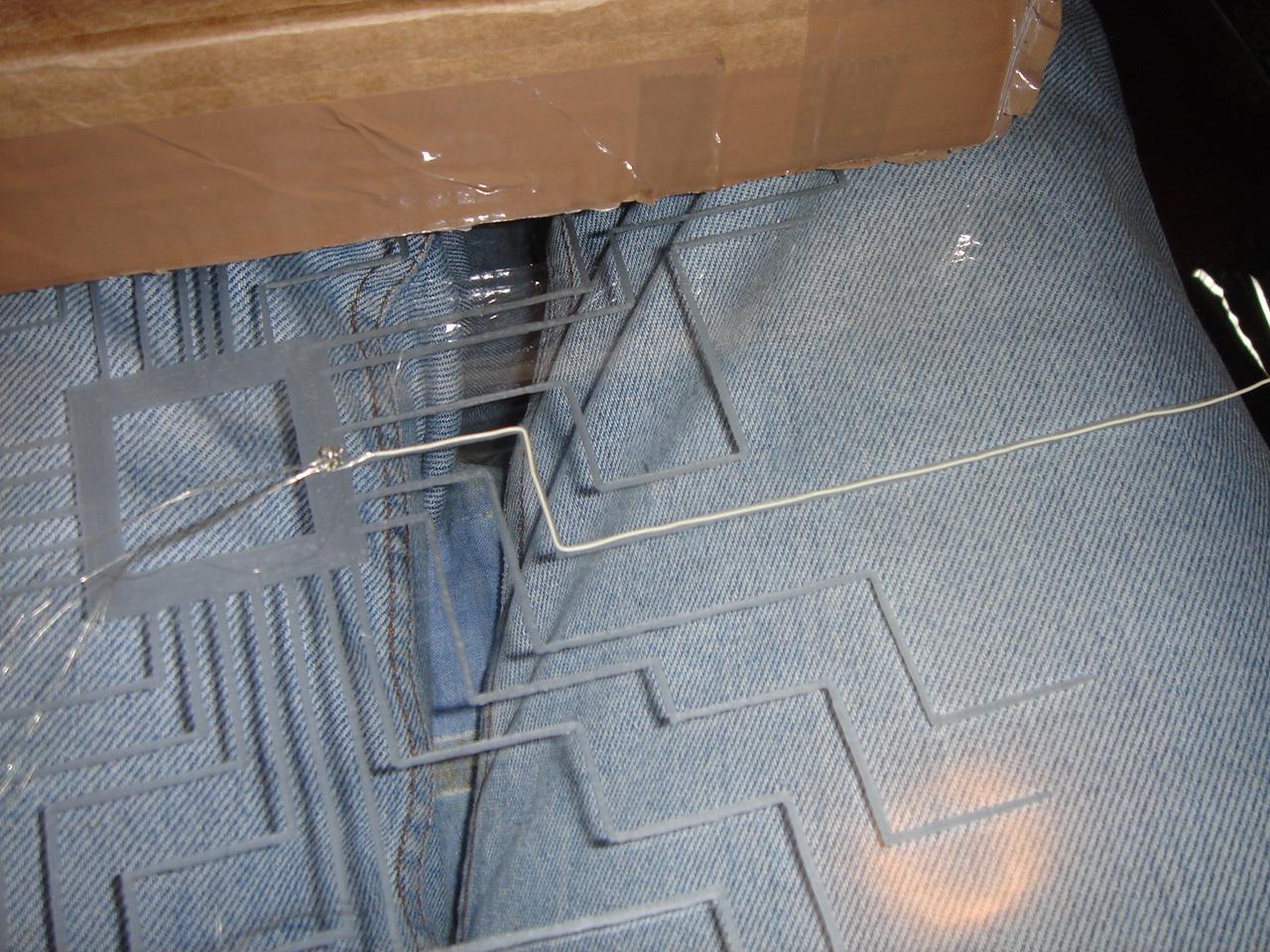
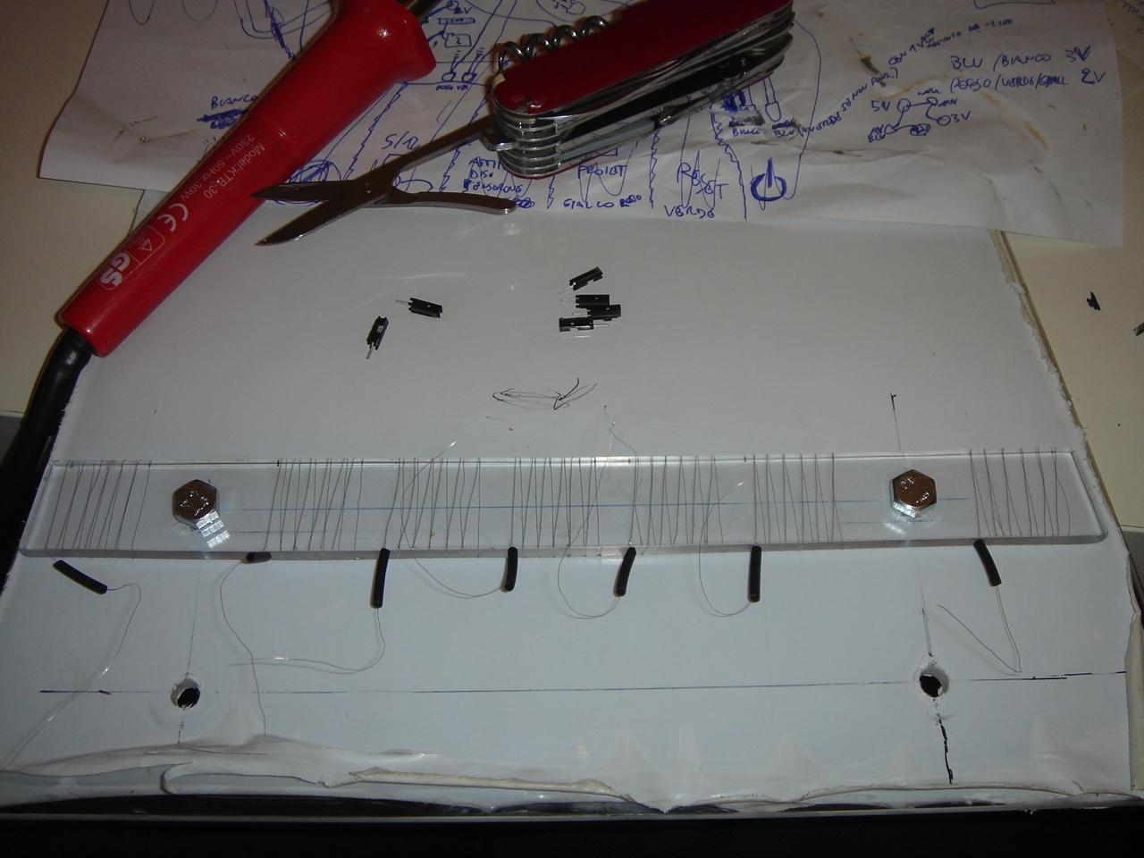
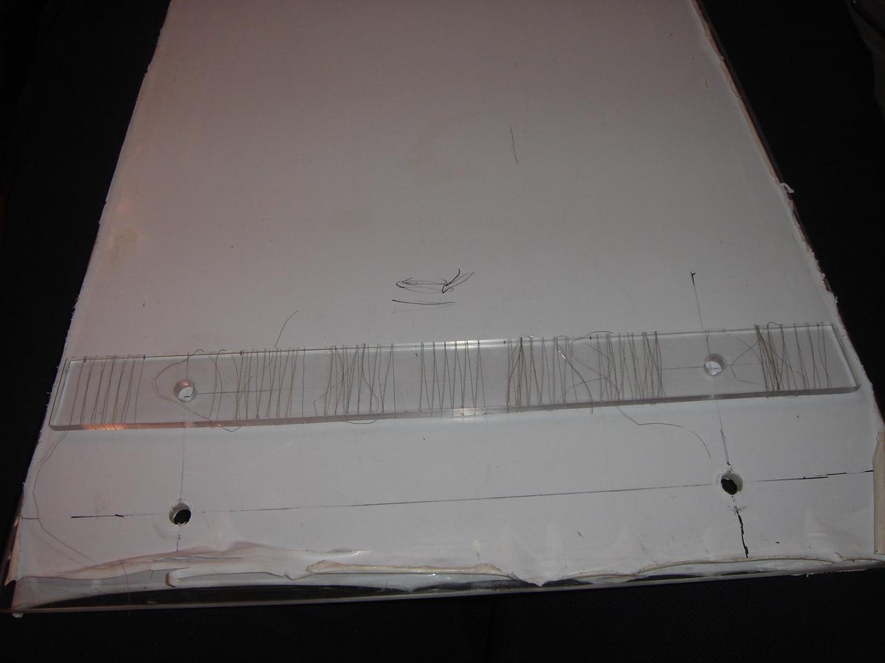
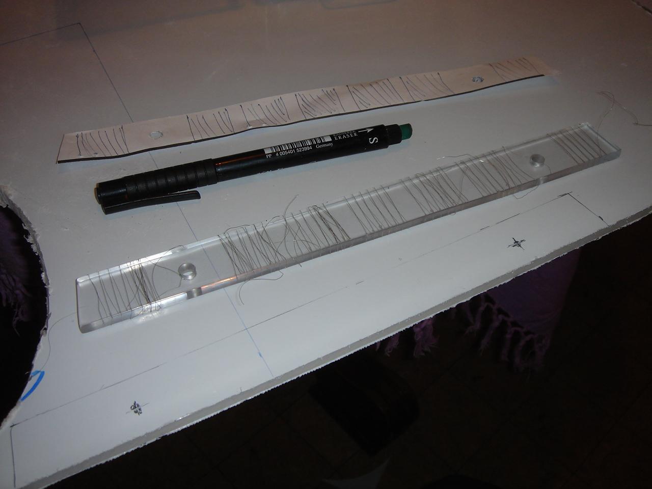
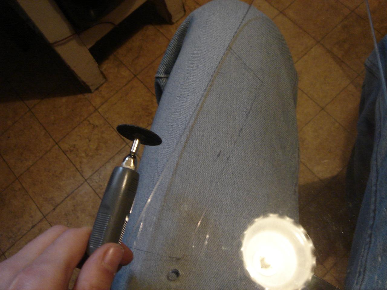
Here I am fixing the thin wires with little pieces of transparent tape, behind each engraving line:
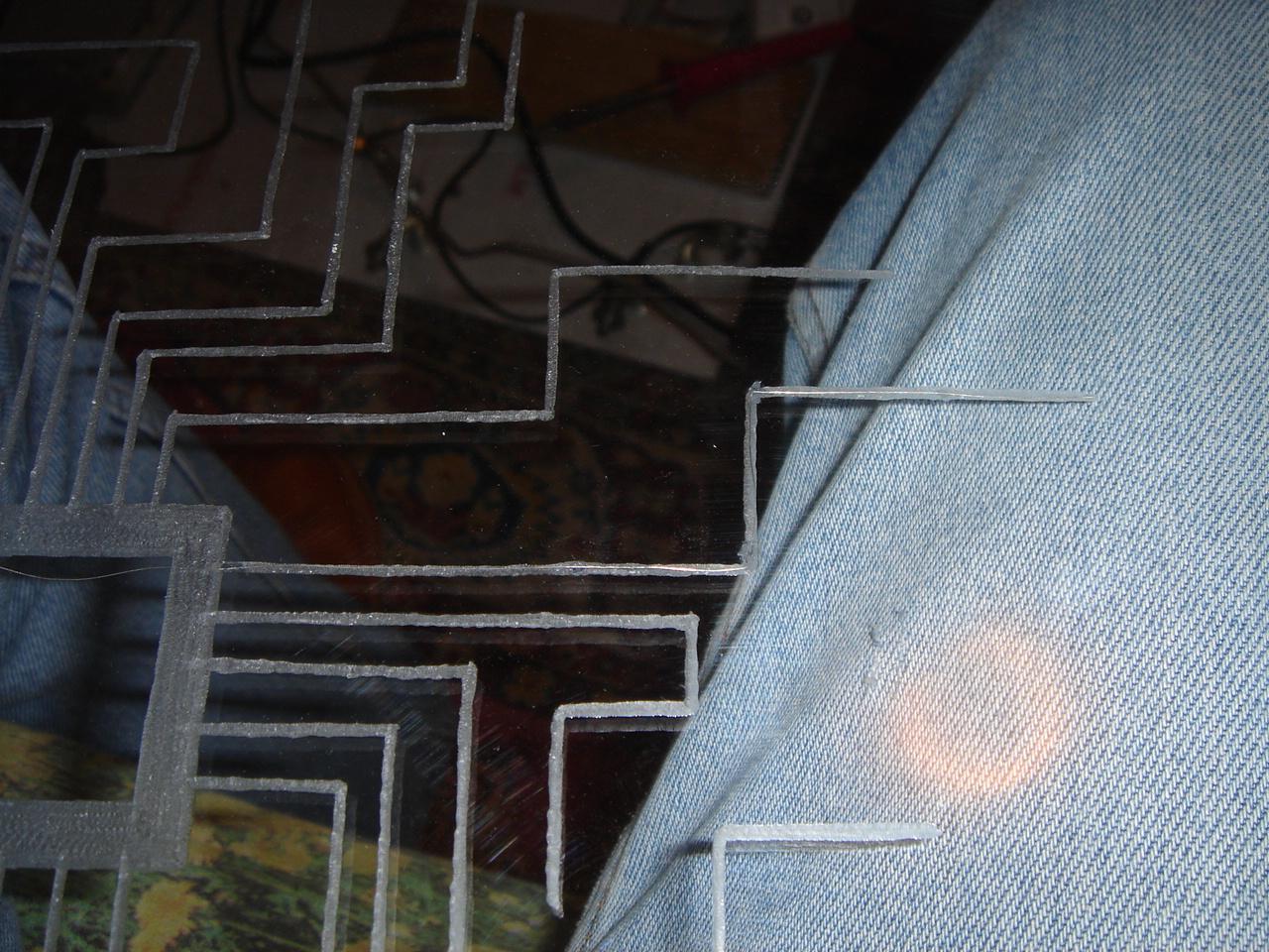
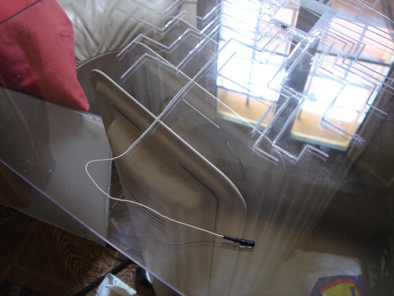
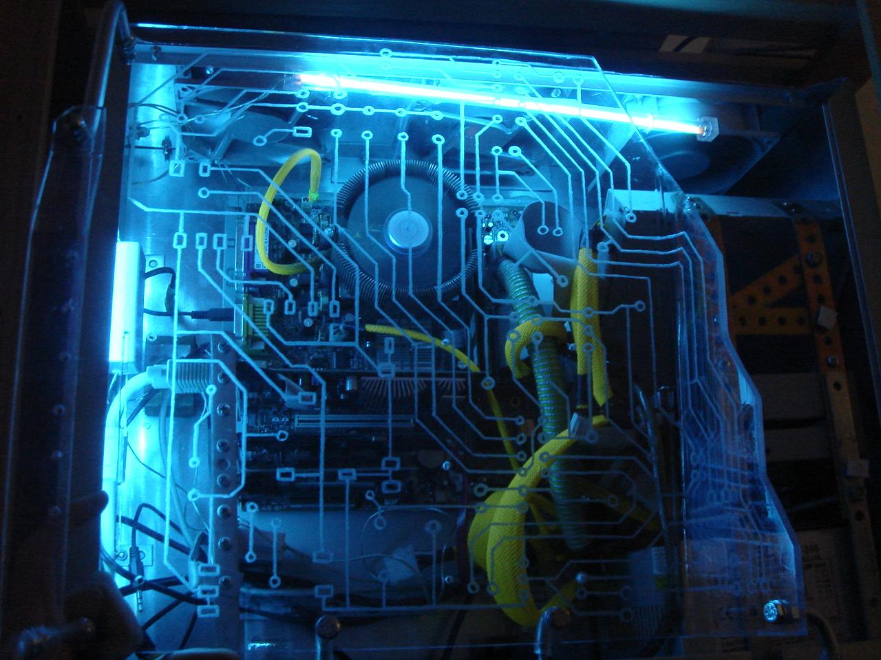
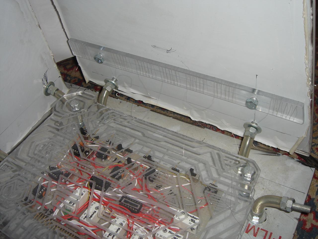
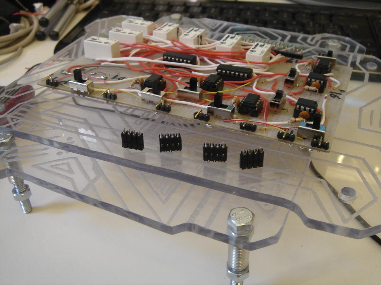
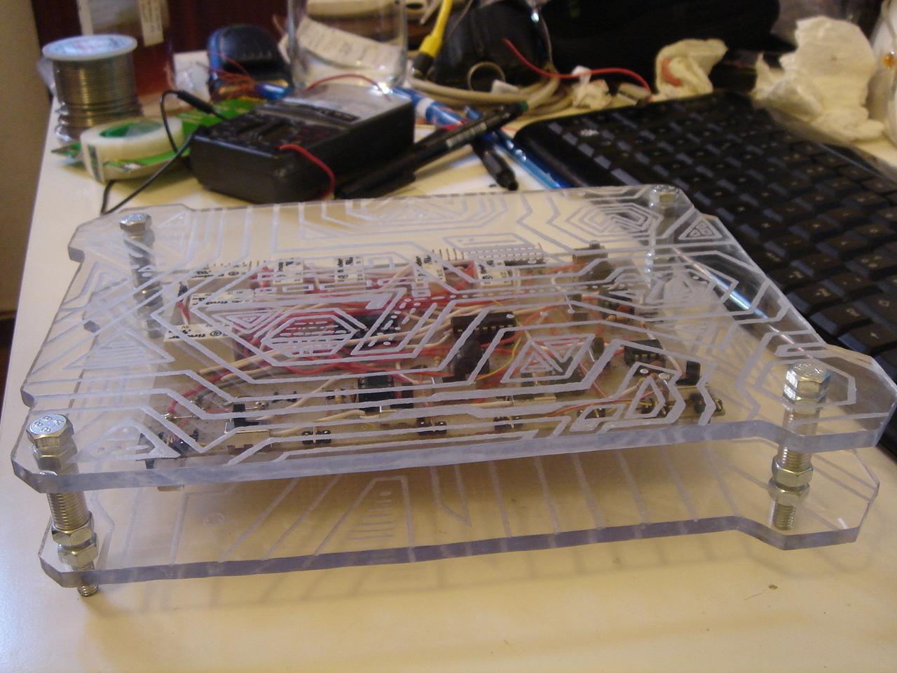
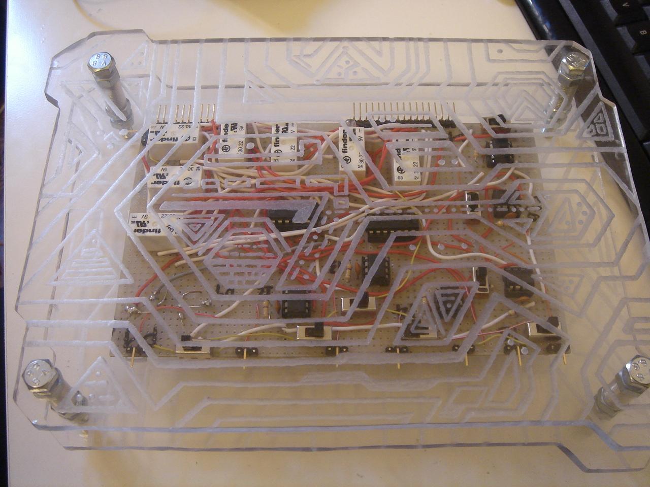
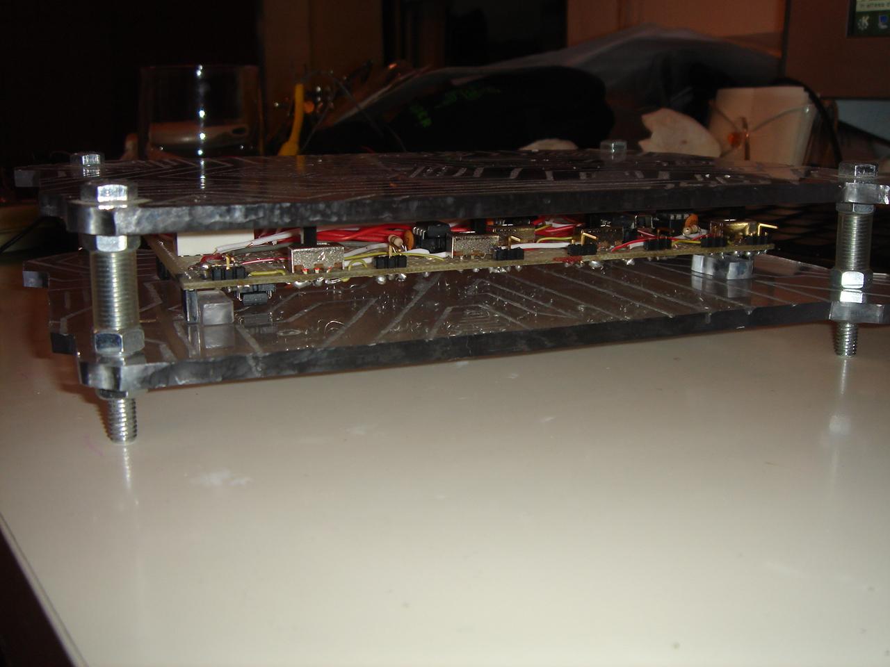
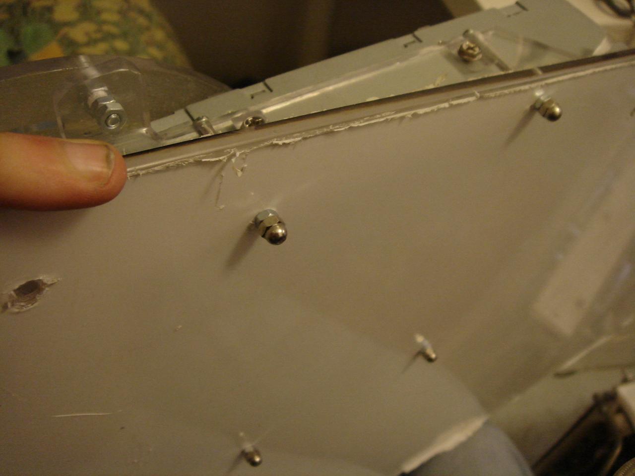
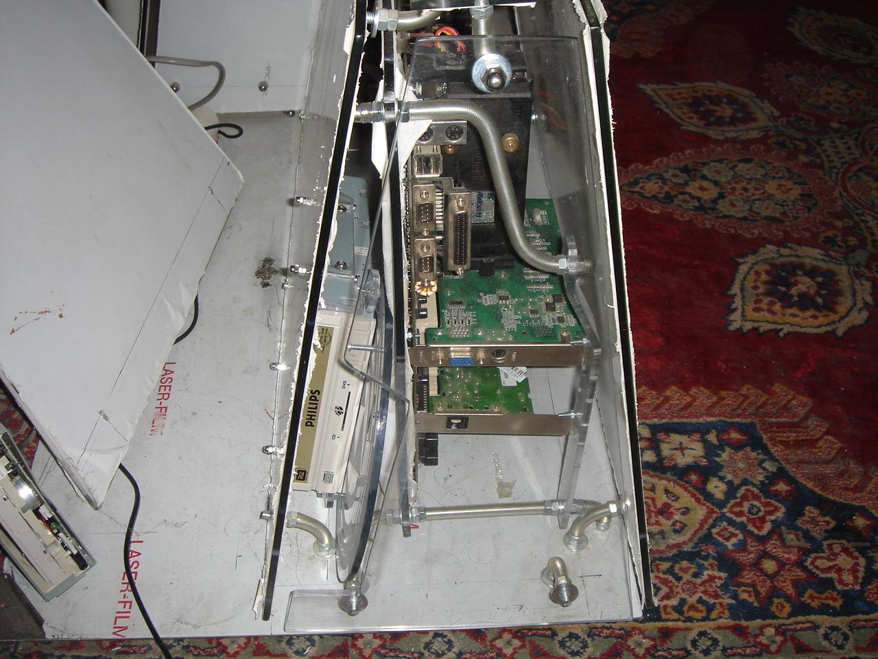
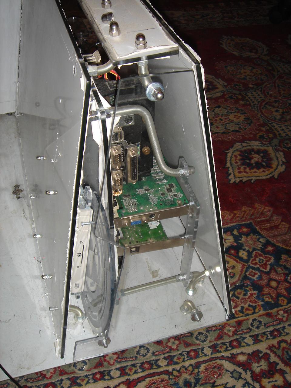
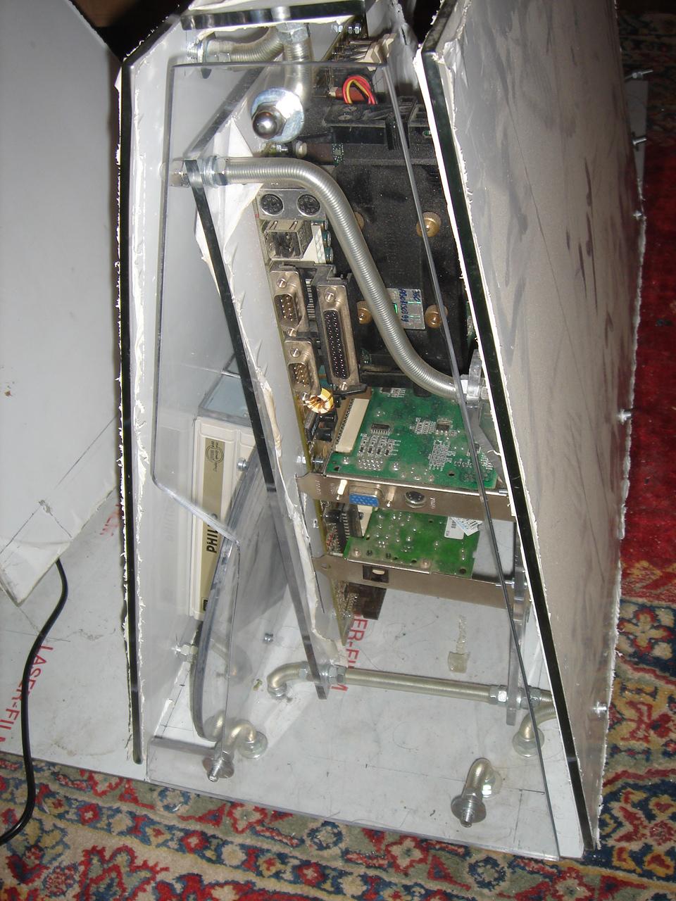
This is the result, as seen from the inside of the case:
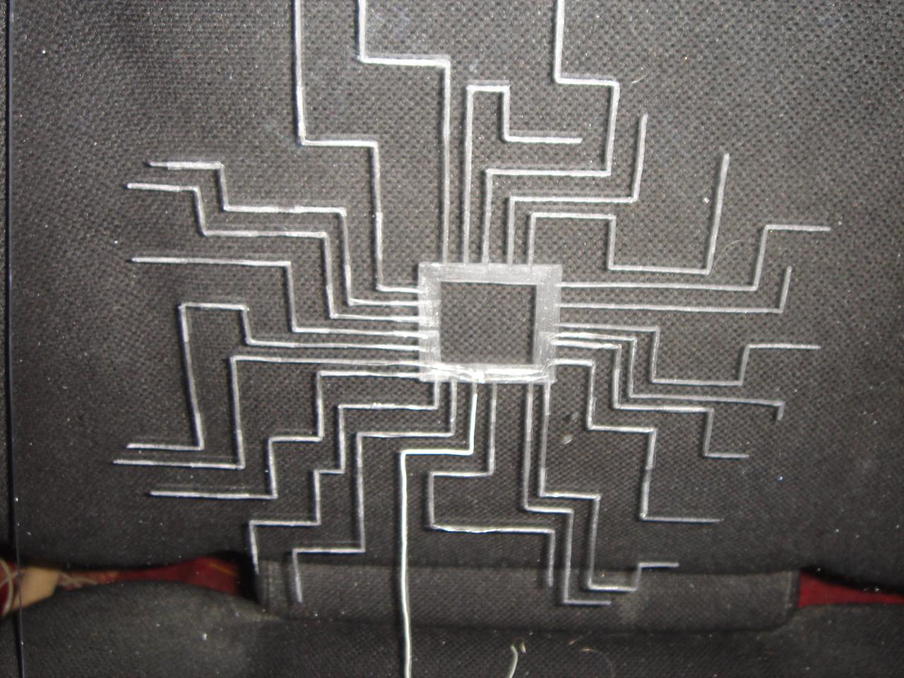
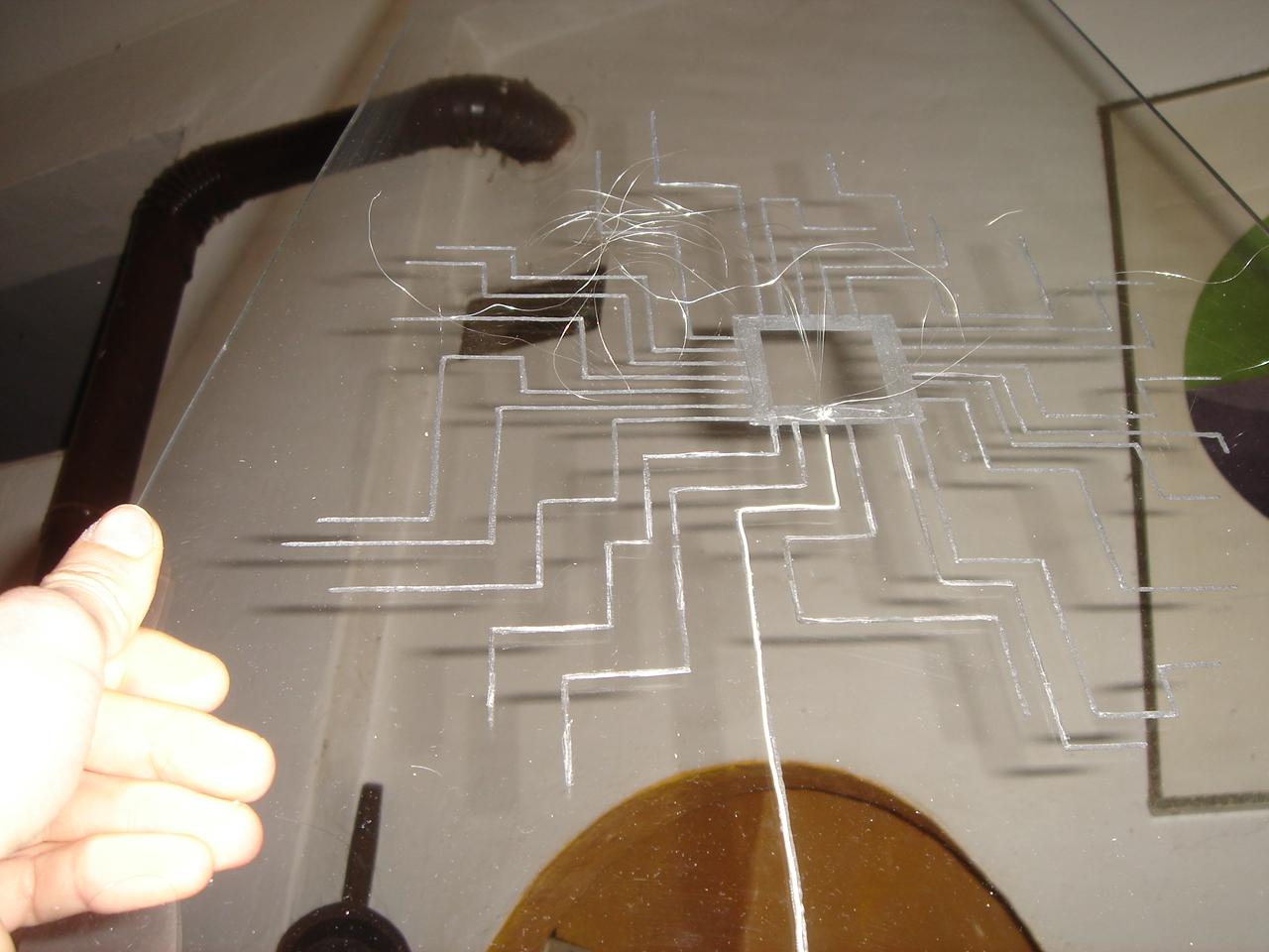
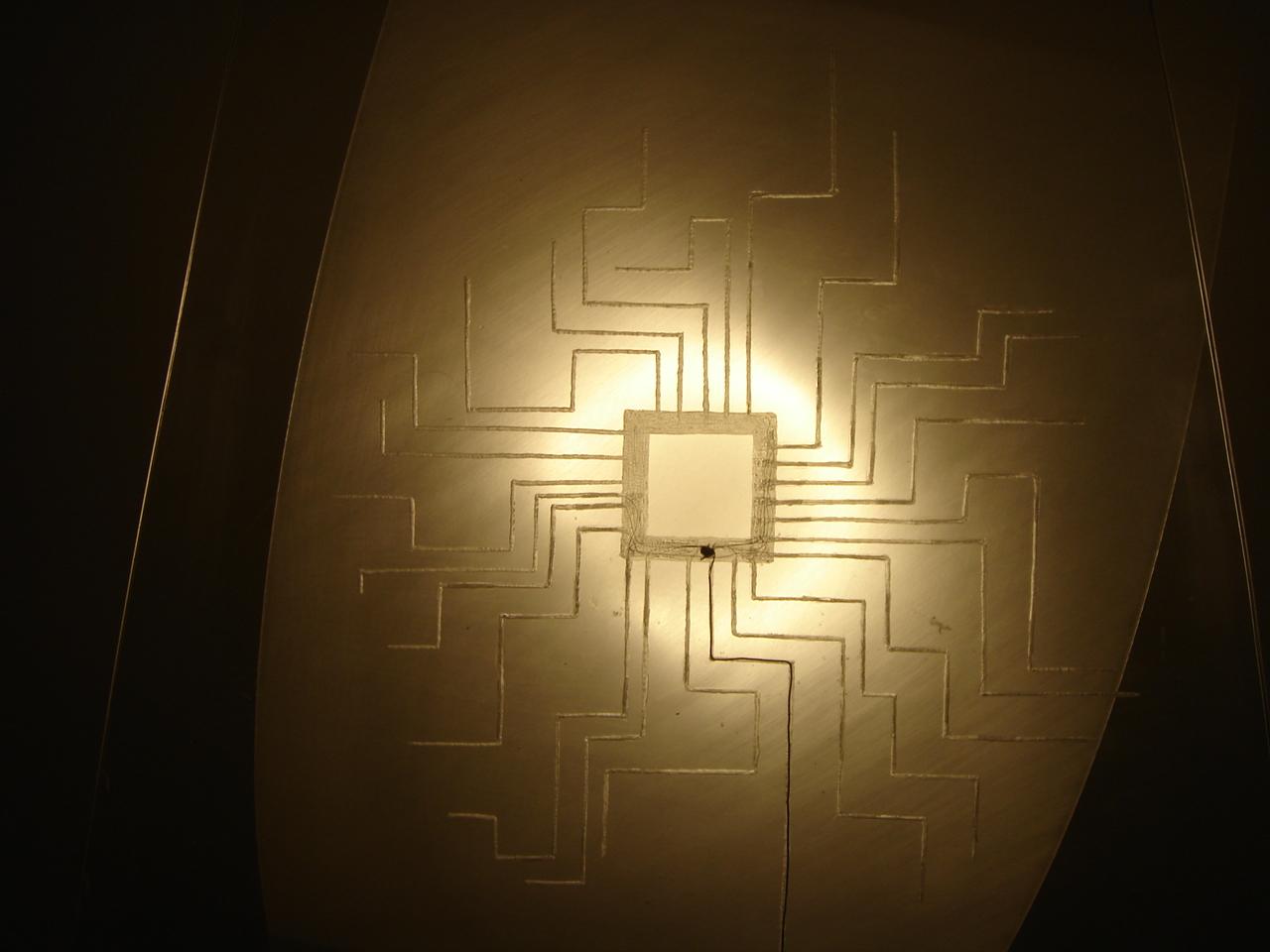
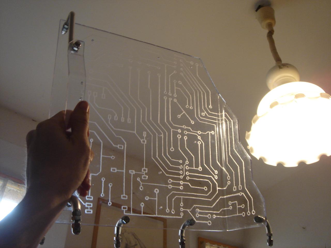
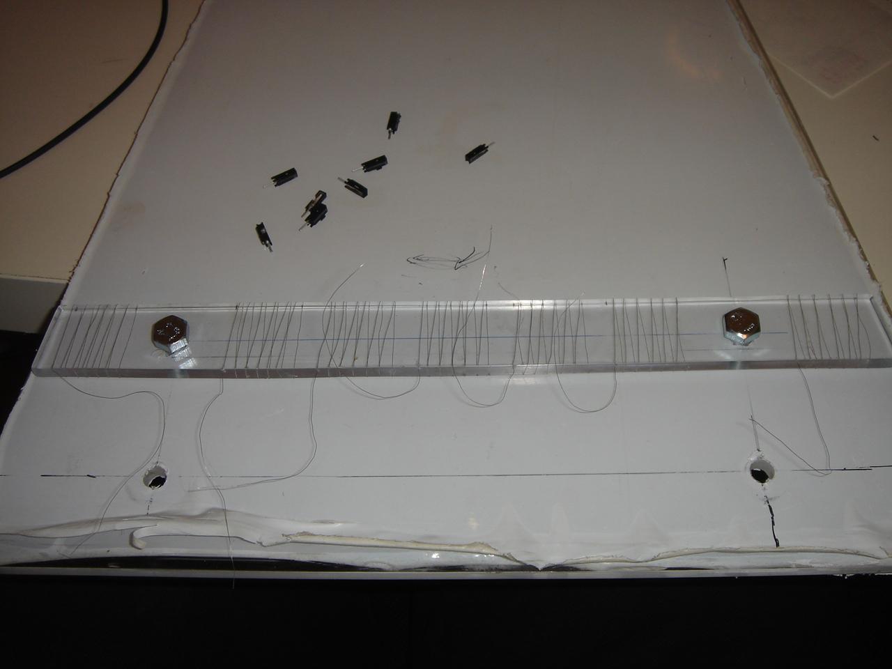
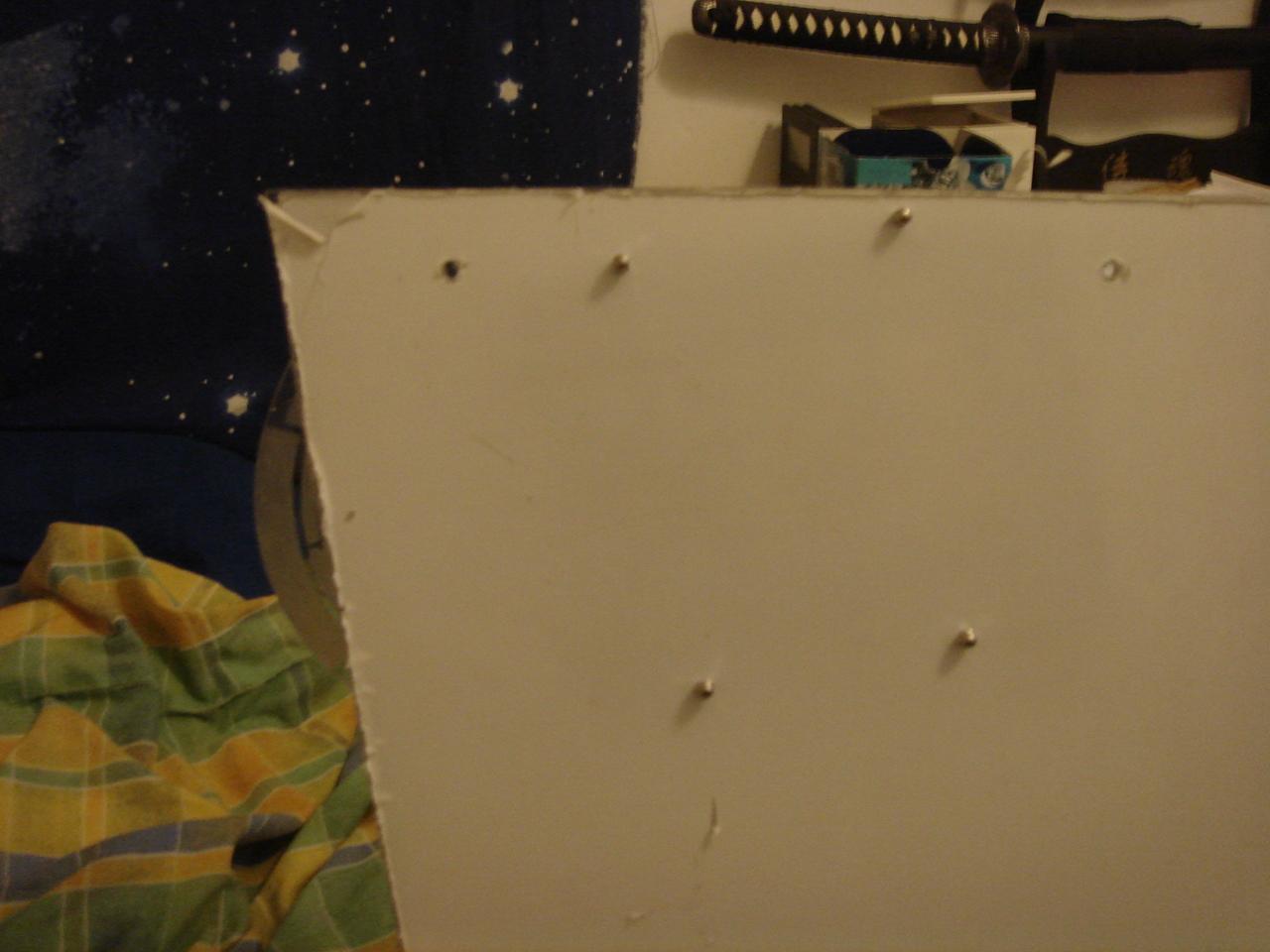
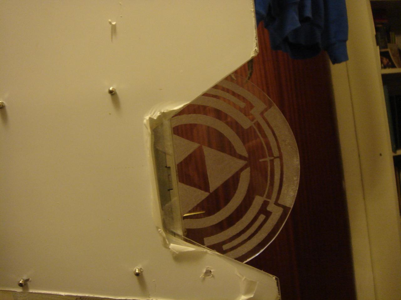
And this is the result seen from the outside (from the outside, the thin wires behind each engraved line are almost invisible, so it seems that the sensor is the engraving 😀 ):
Finally I soldered the big wire to a connector for the circuit:
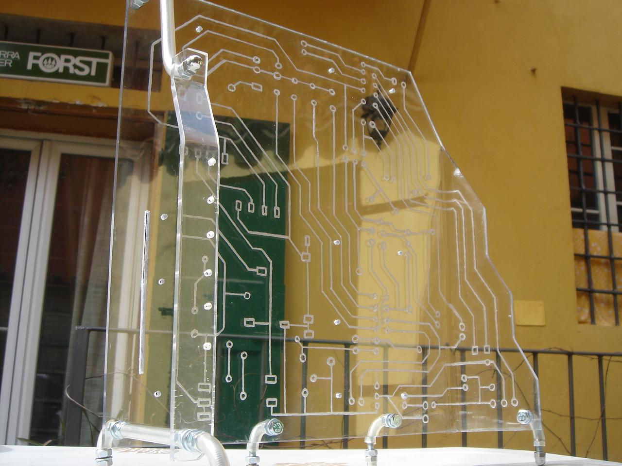
engraving of the proximity sensor panel
Now it’s the turn of the proximity sensor engraving…
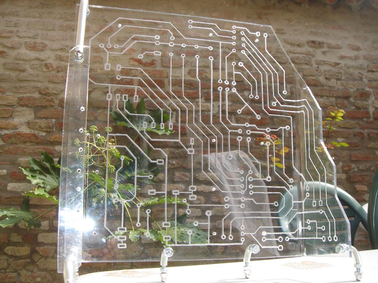
The proximity sensor is a radial net of thin copper wires, so my idea was to hide each wire behind a line of an engraving.
With this method, the proximity sensor is totally invisible, and it seems that the sensor IS the engraving.
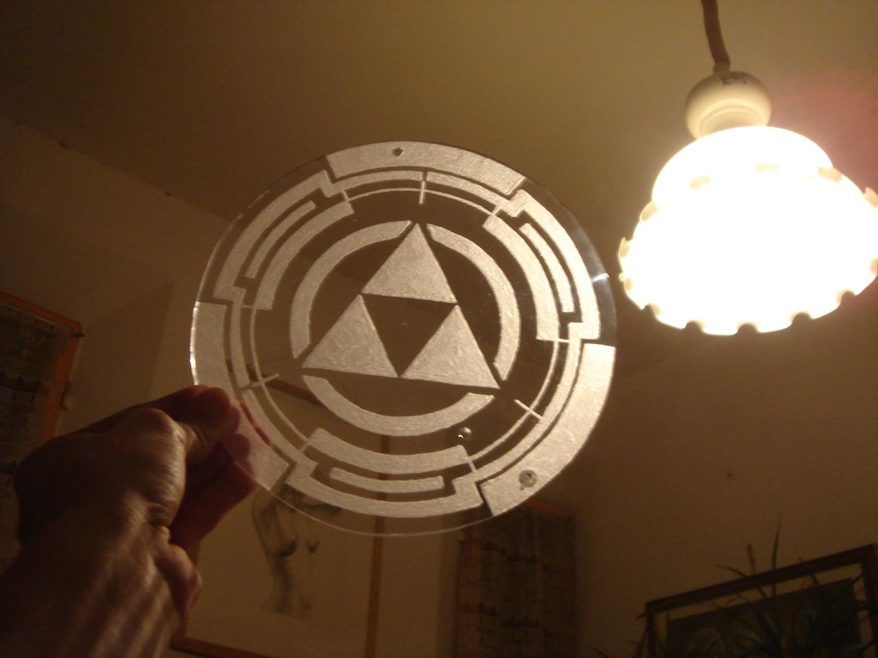
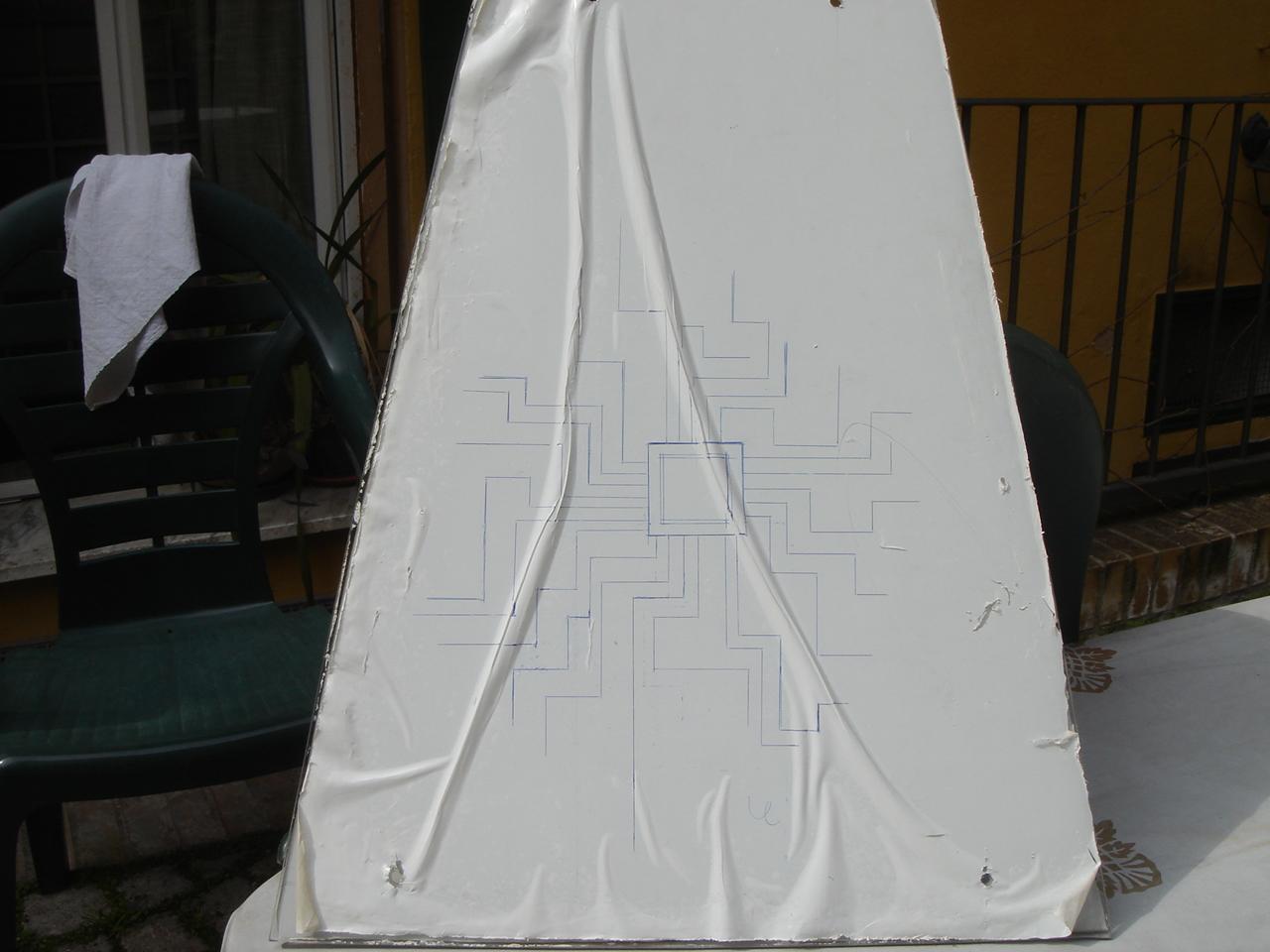
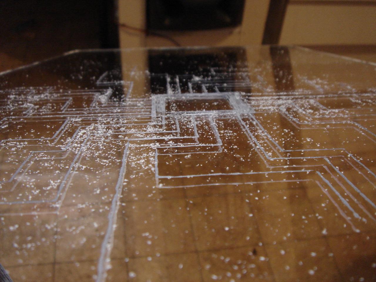
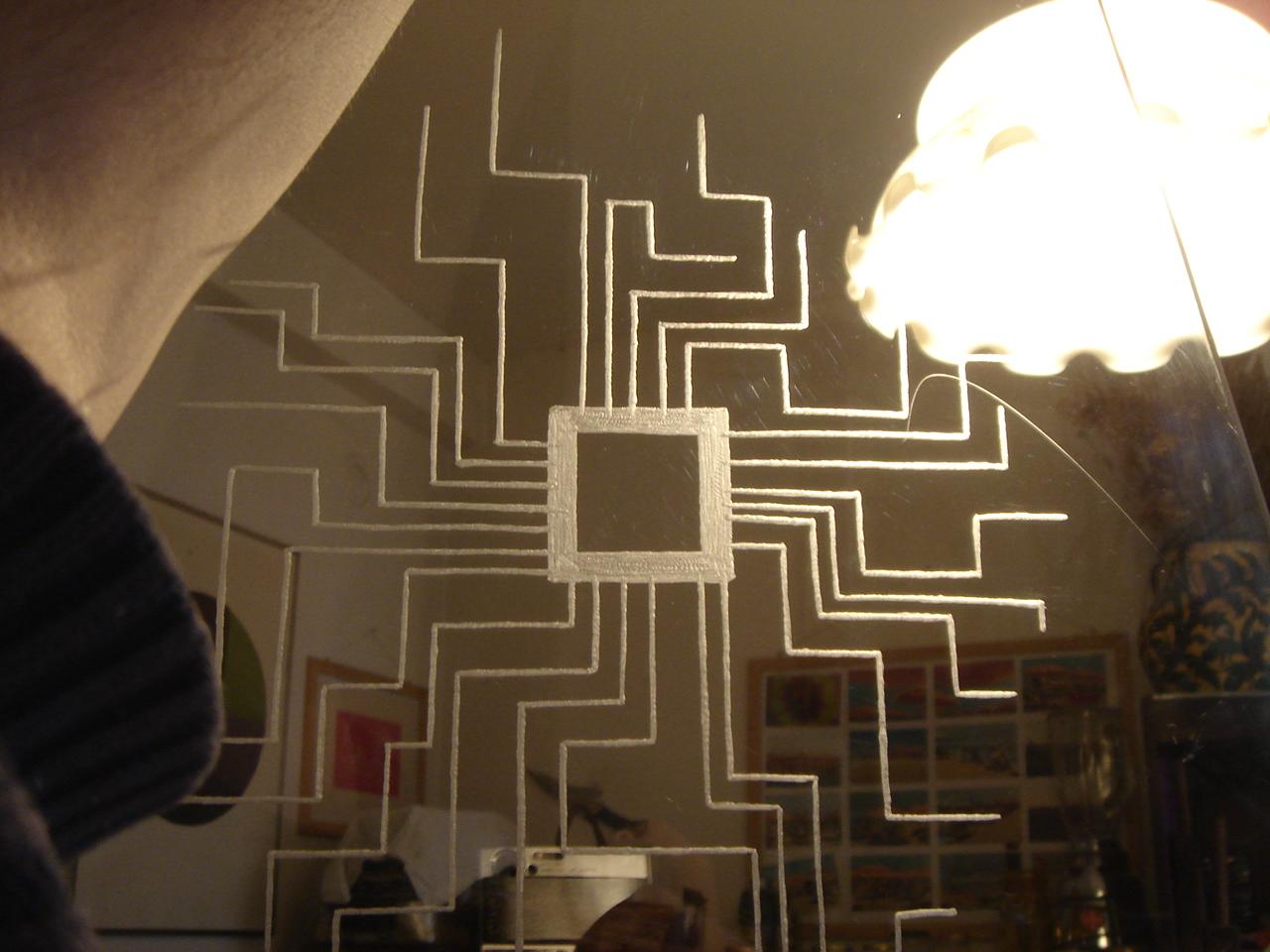
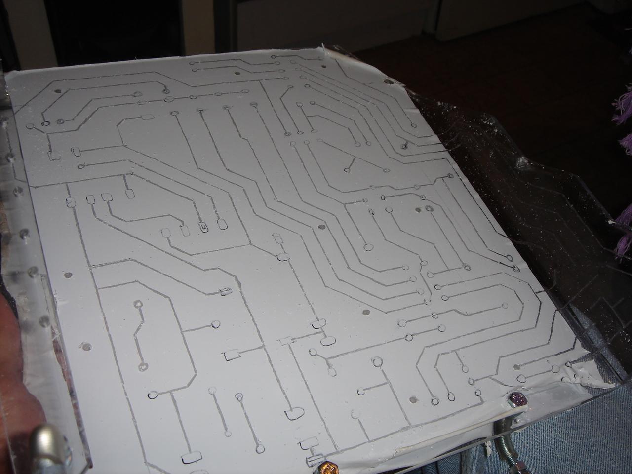
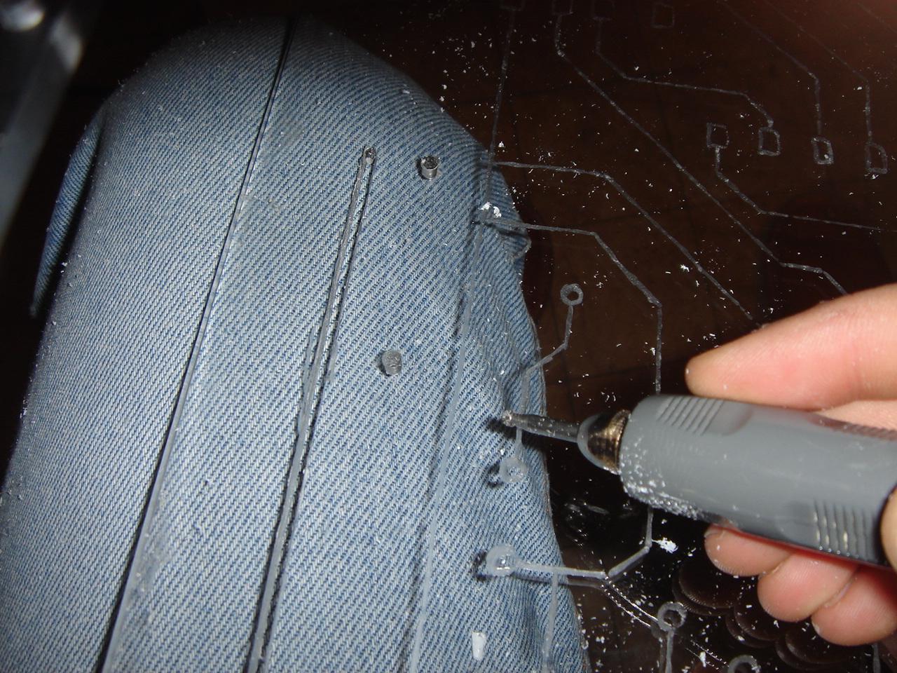
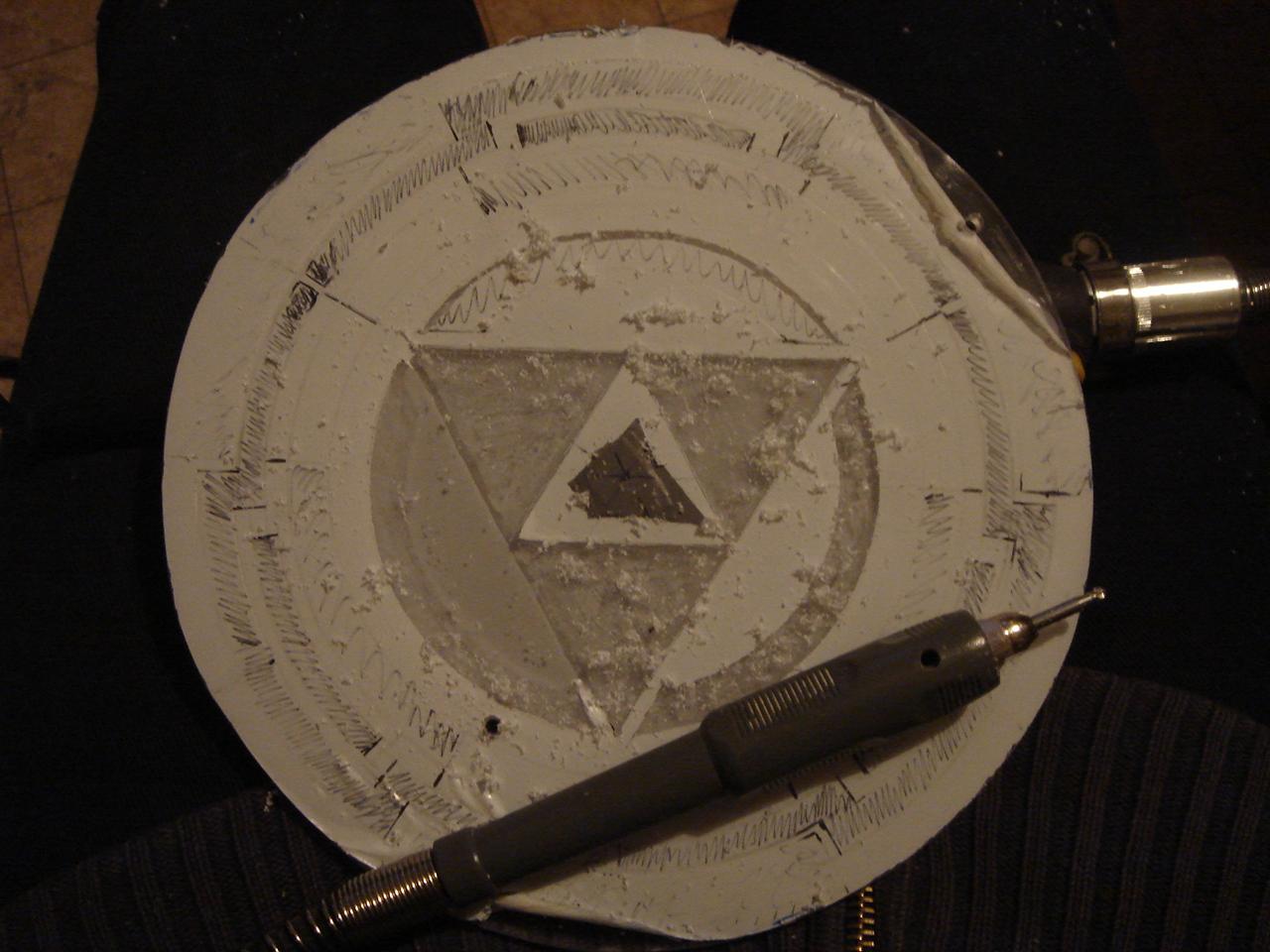
Drawing and first pass of the engraving:
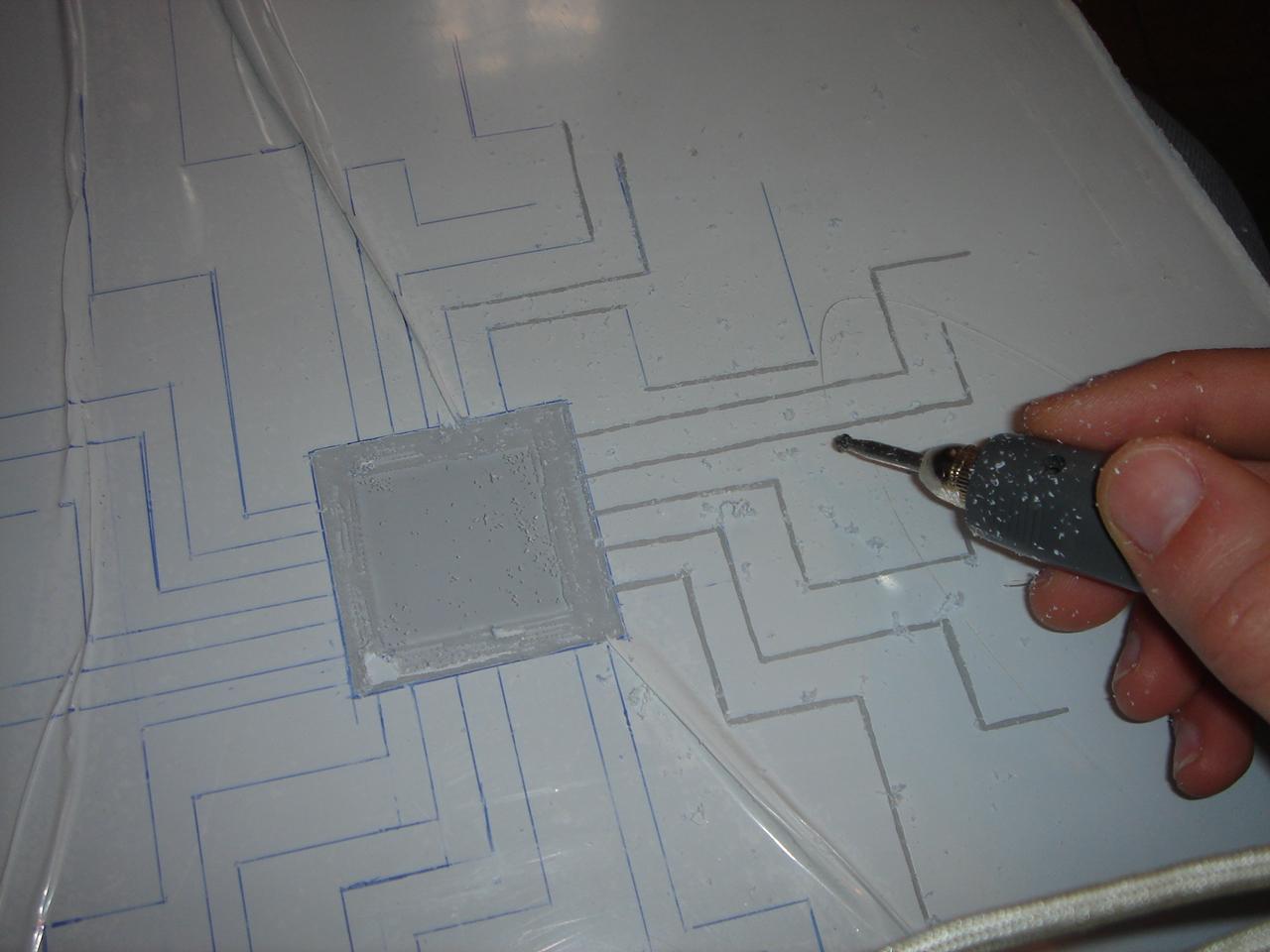
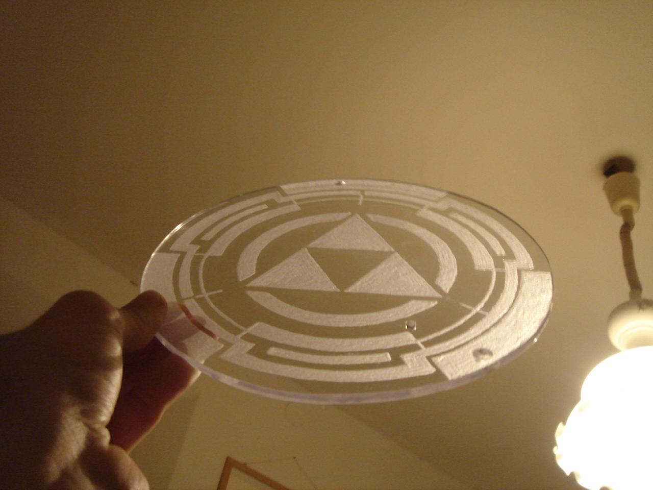
Second pass:
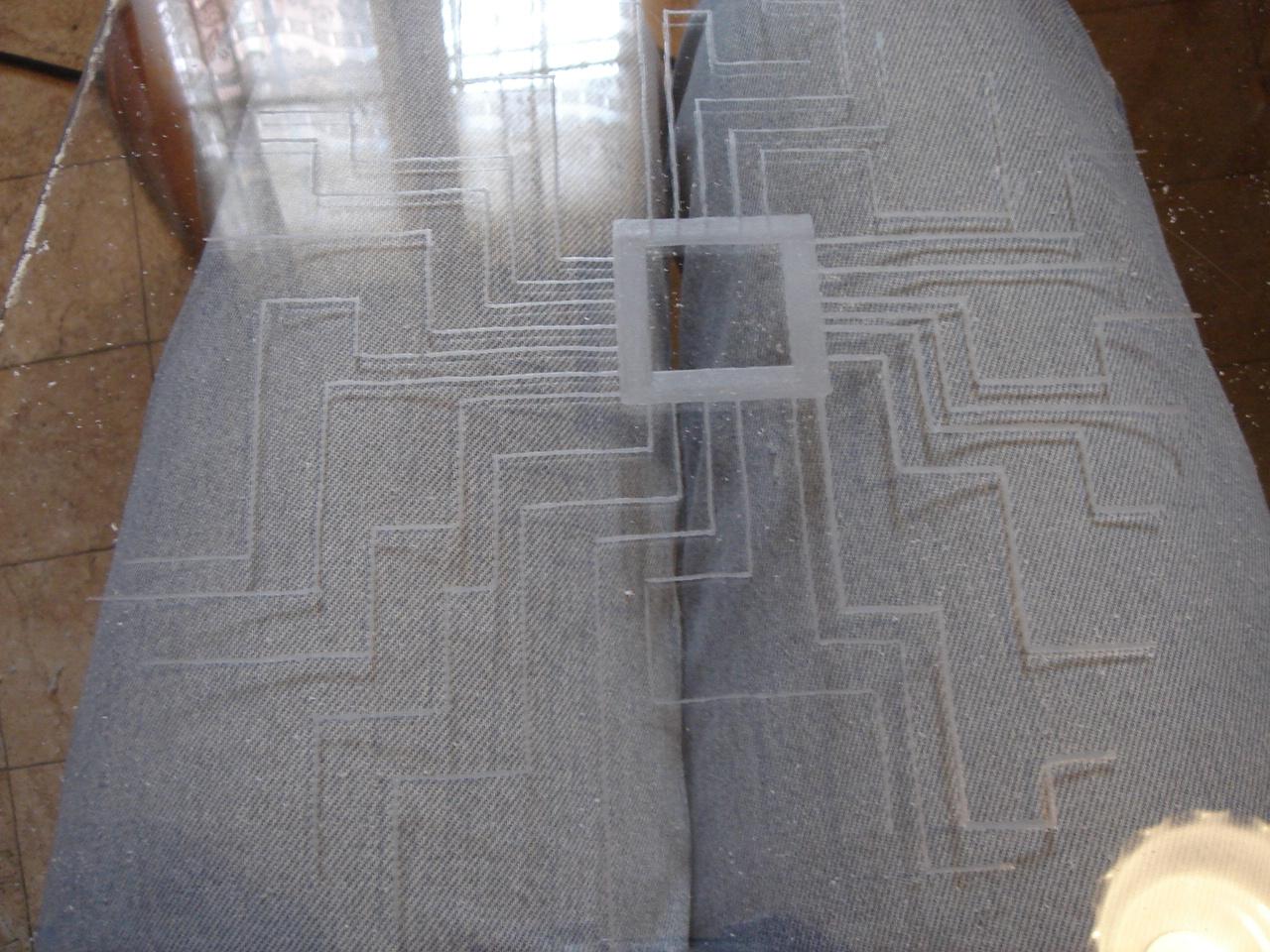
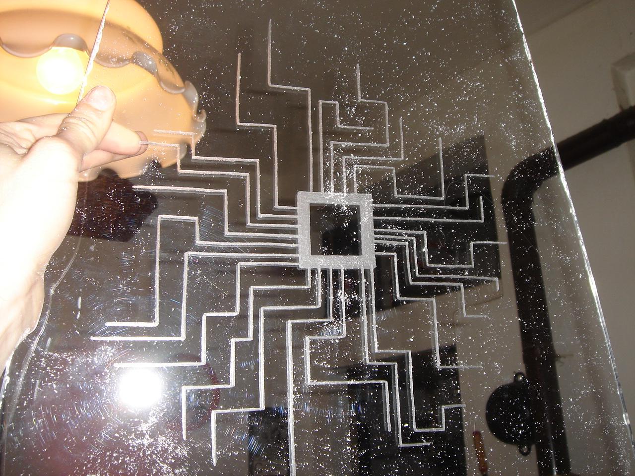
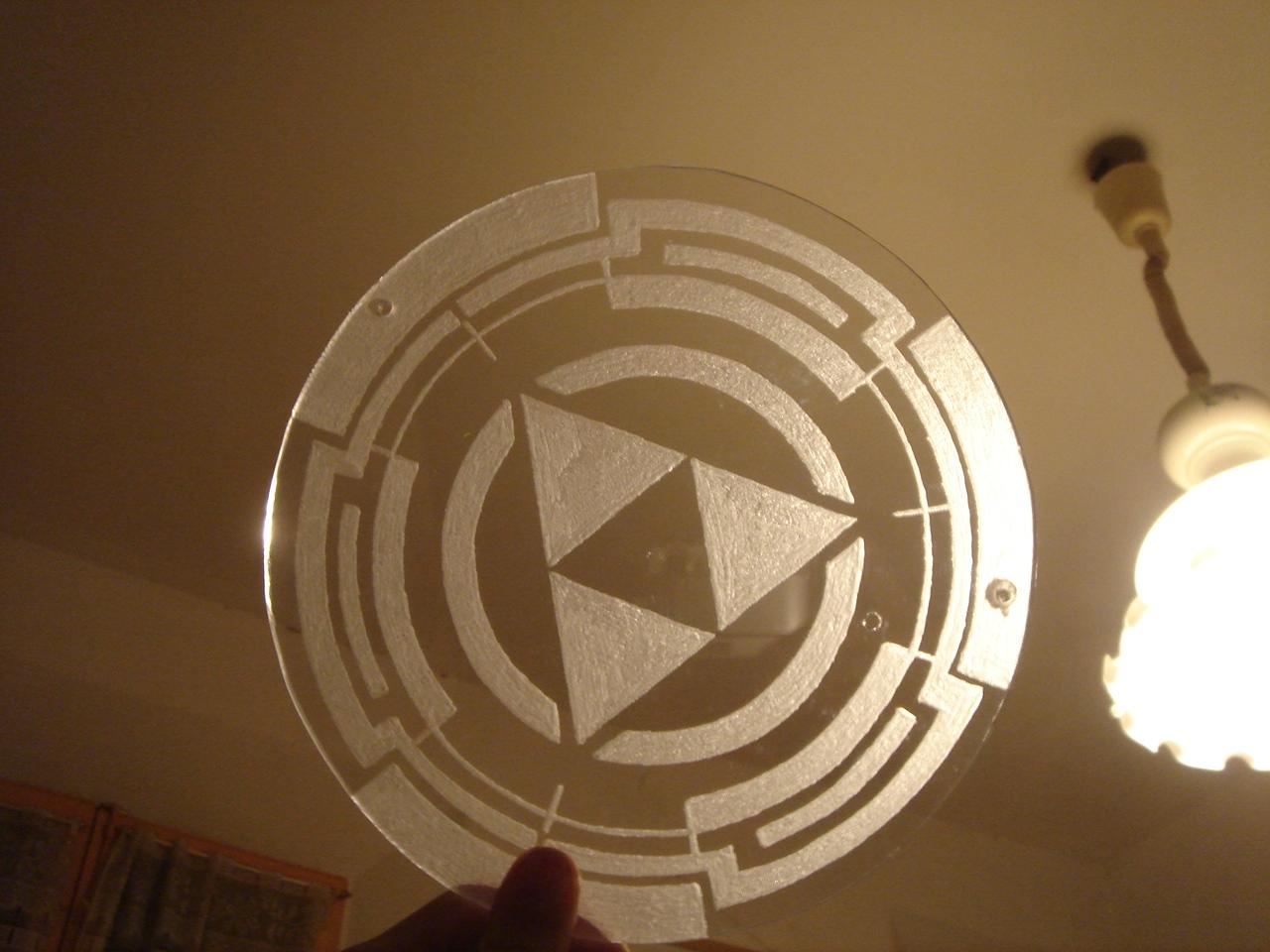
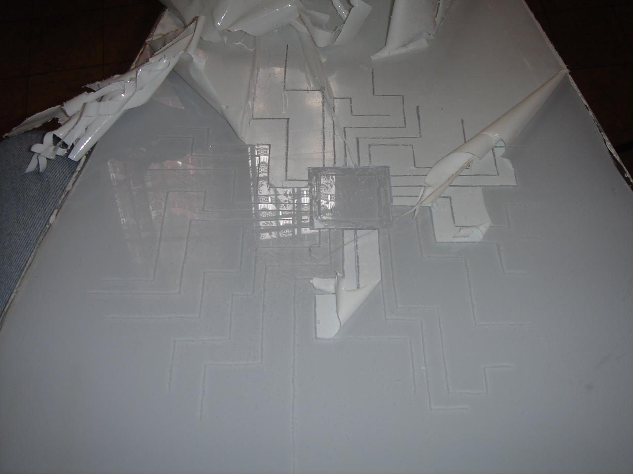
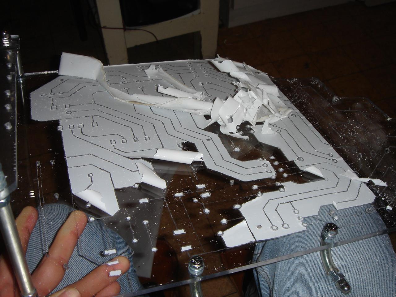
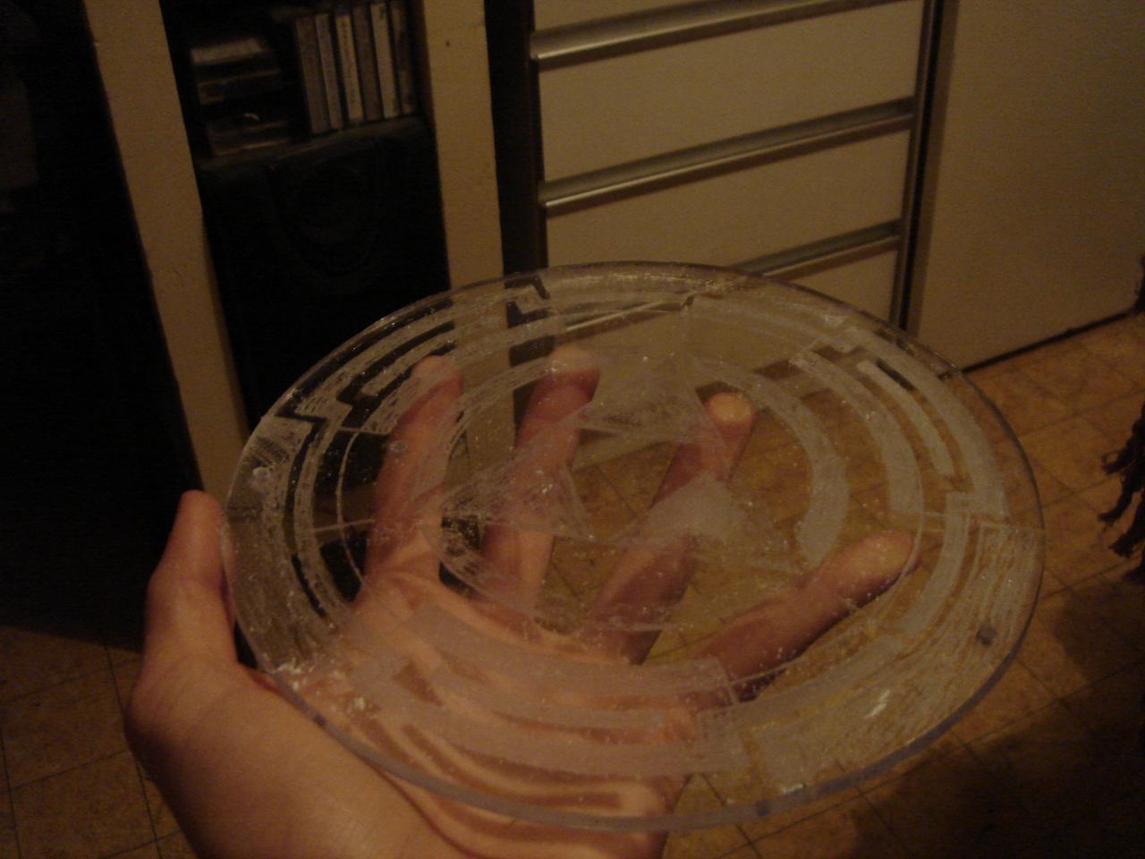
Washing the panel:
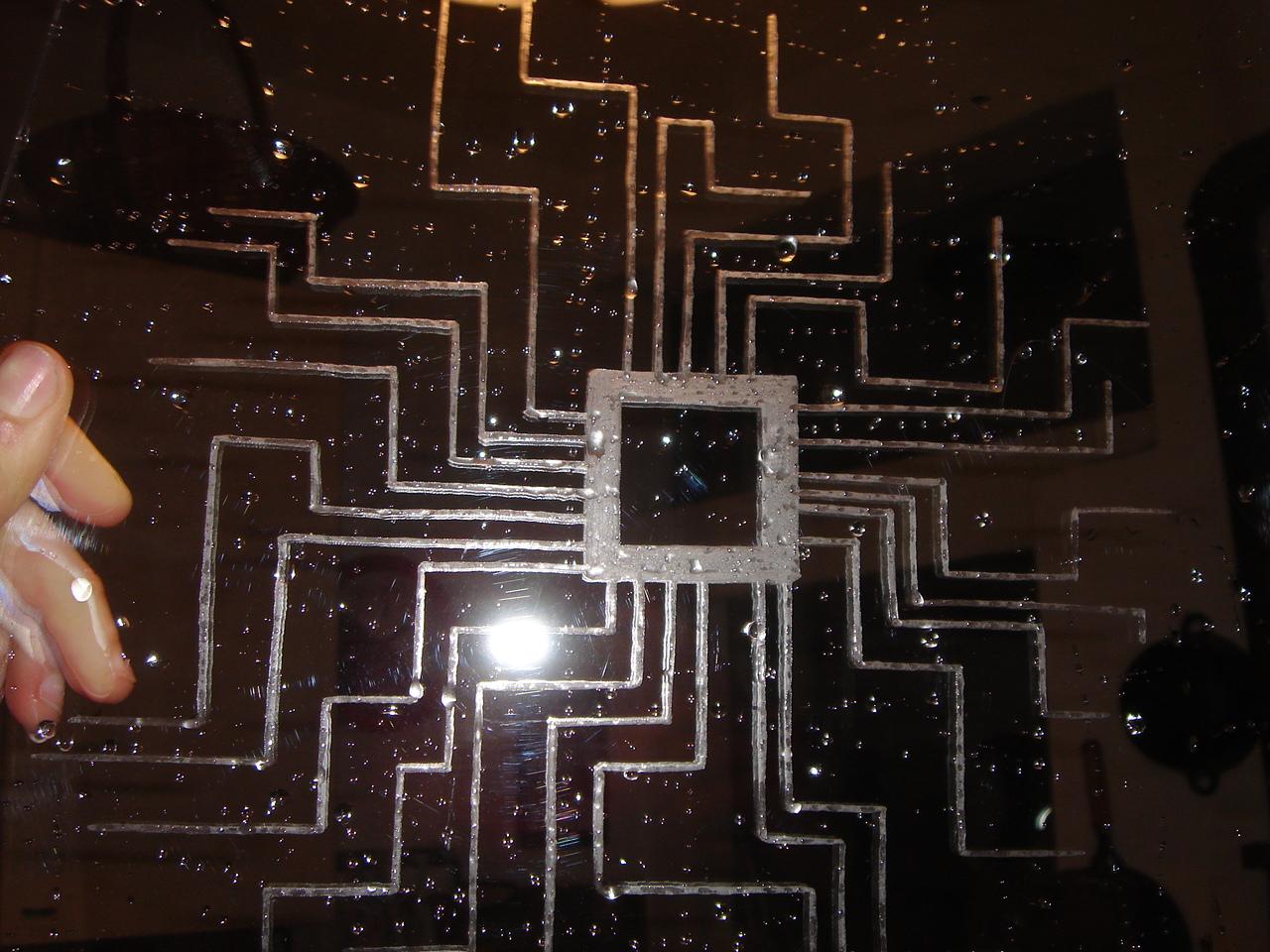
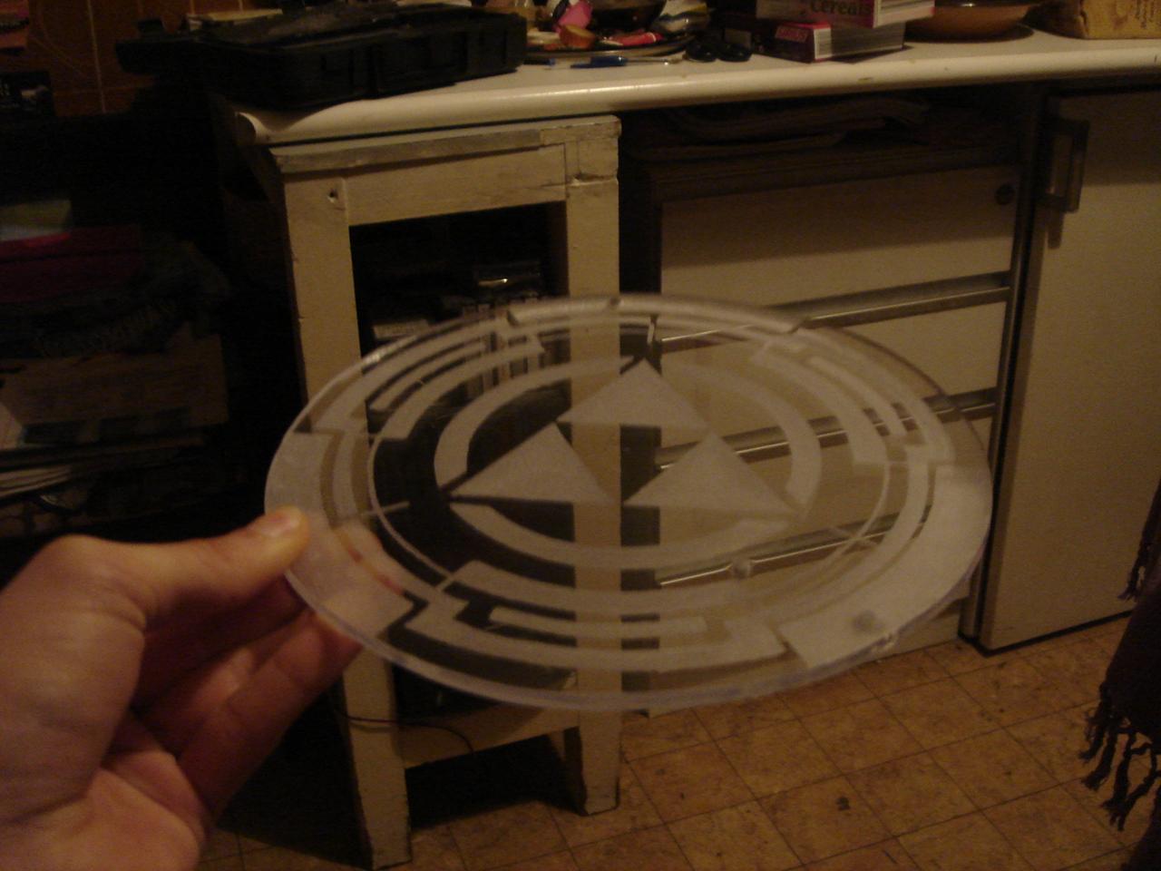
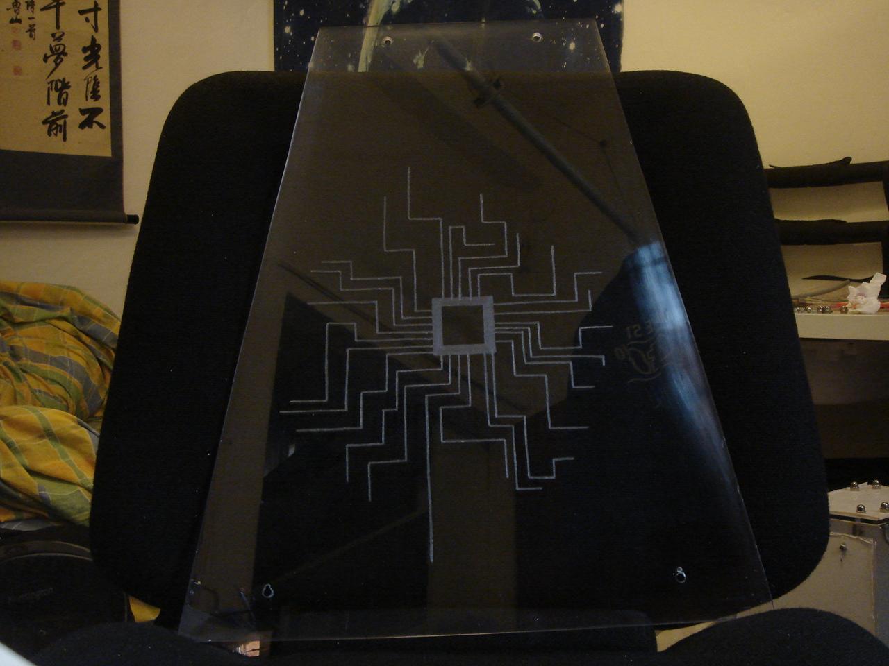
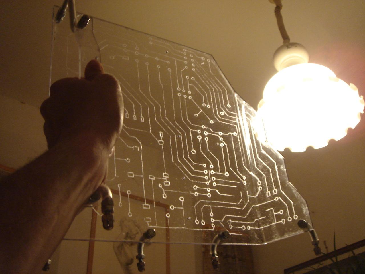
The final result:
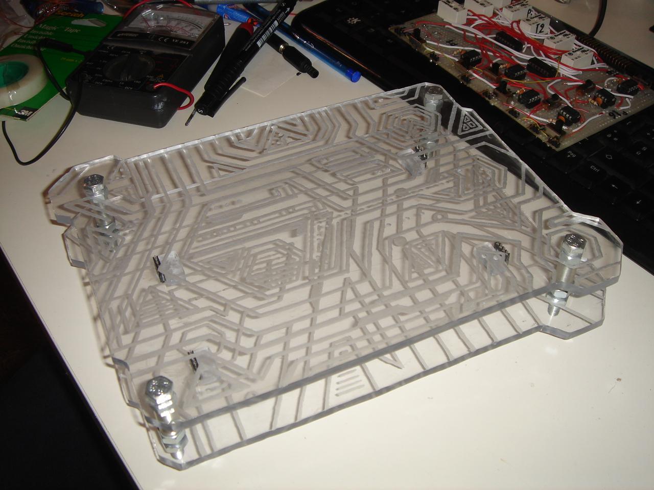
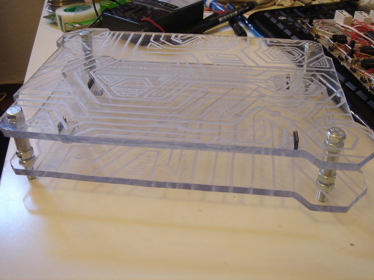
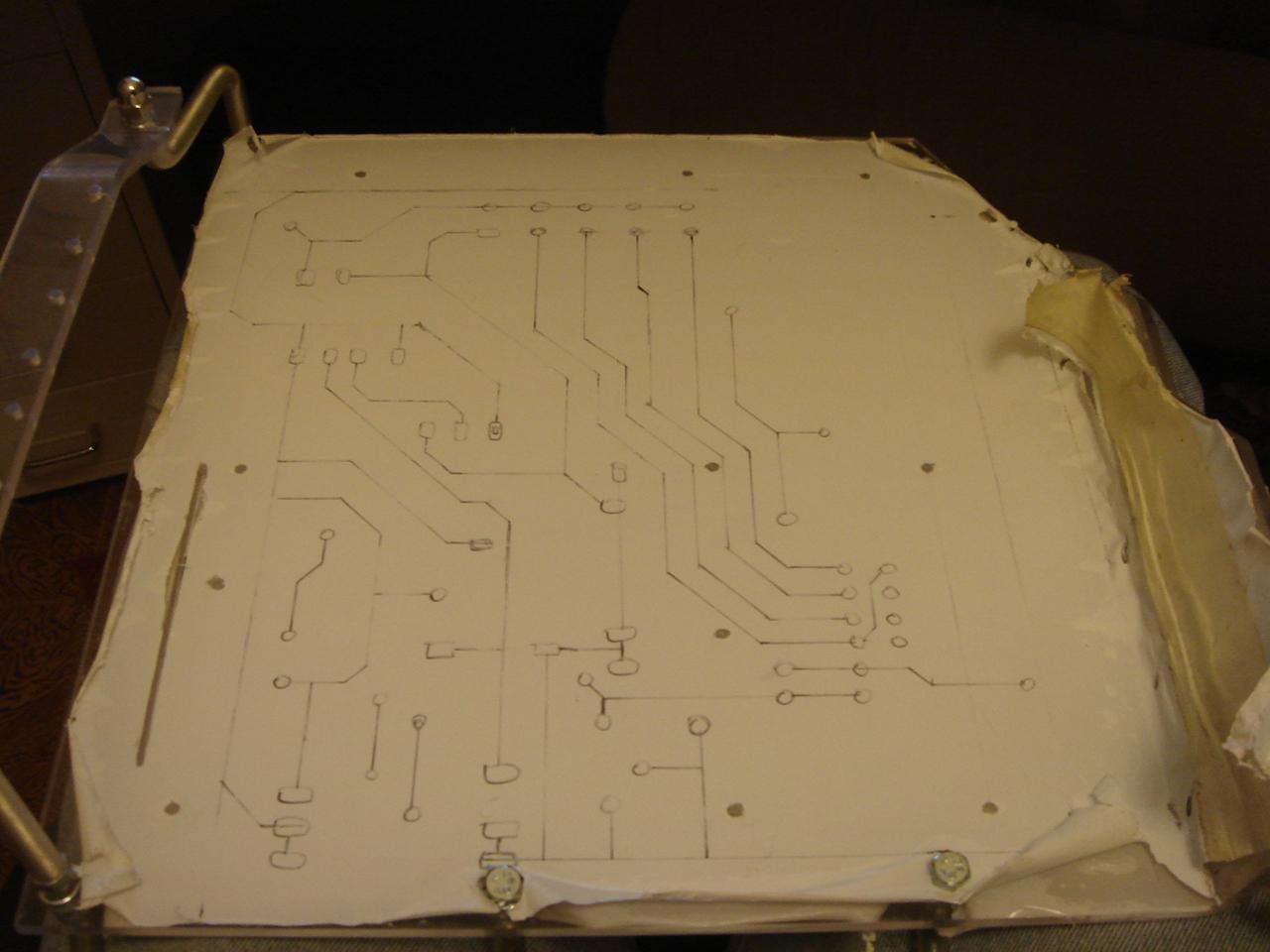
engraving the motherboard structure
At this point I was tired of soldering, so I finished to draw the fake circuit to be engraved on the motherboard structure. This is the result:

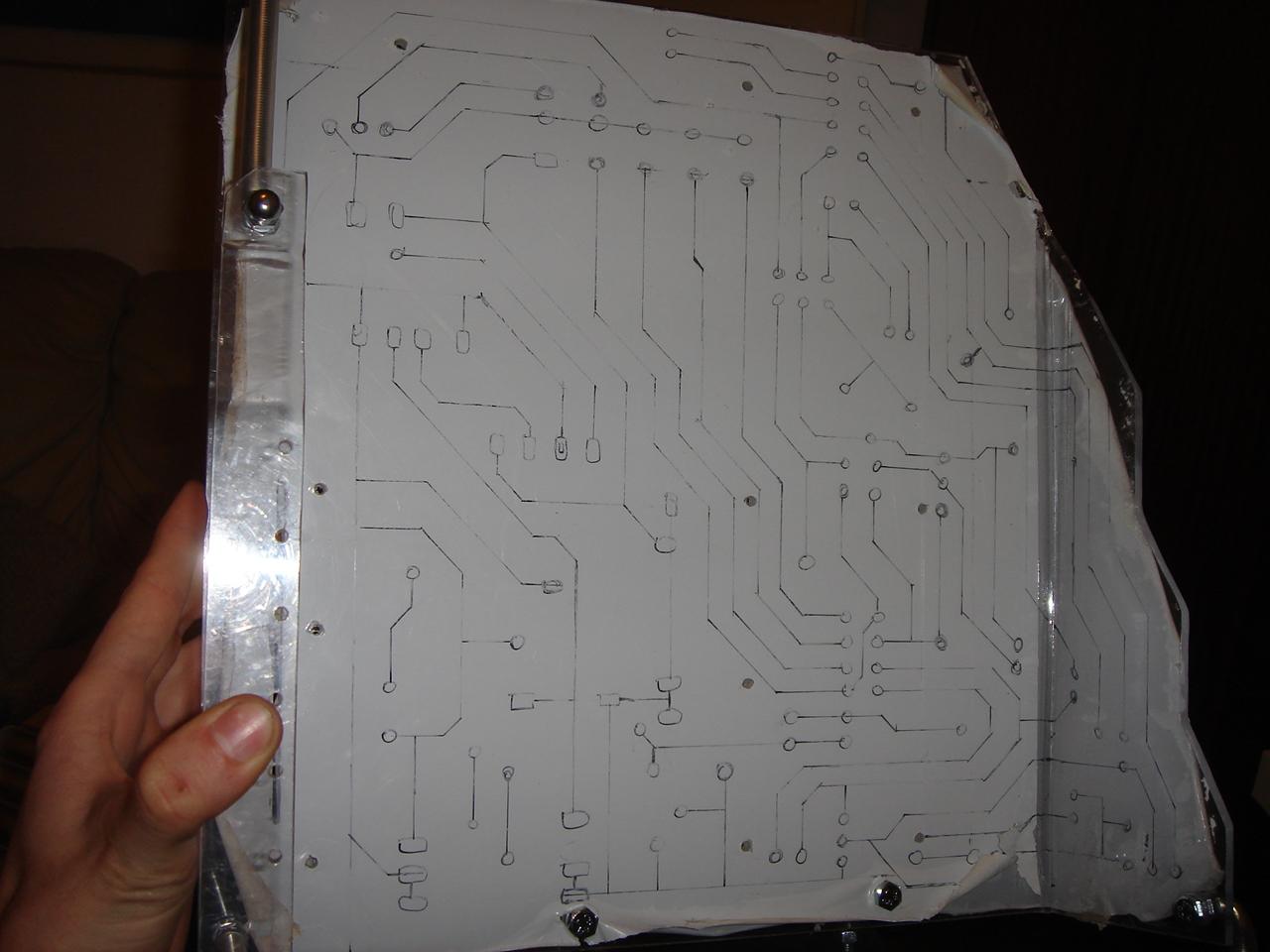
Then I engraved the drawing.
first pass:
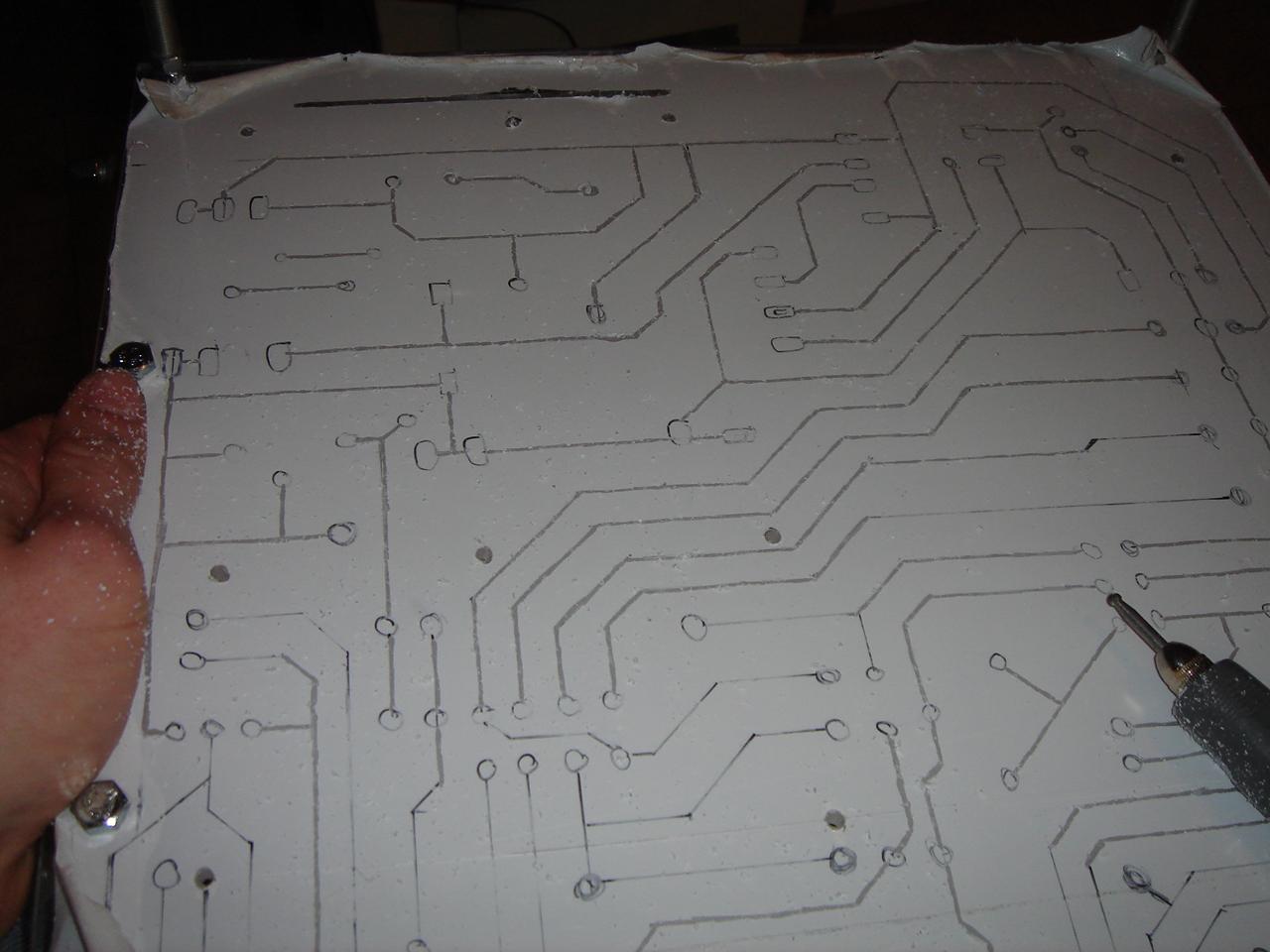
Second pass (this pass has been a lot longer than the first. The first took half an hour, and the second took 3-4 hours):
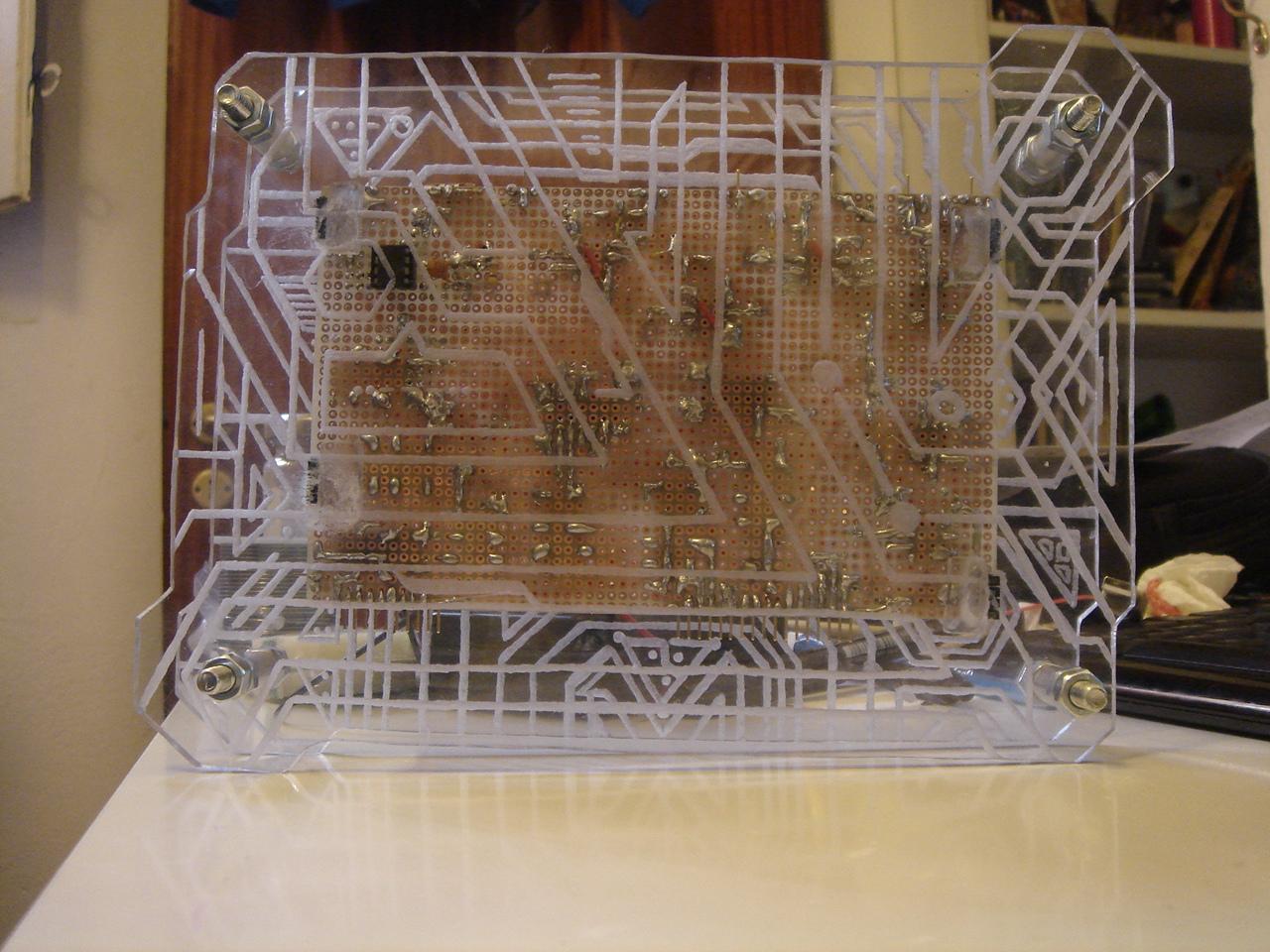
And this is the finished engraving:
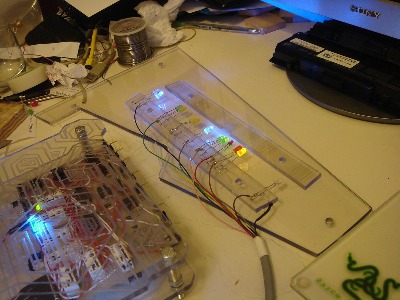
VIDEO and photos testing the touch sensors and their feedback LEDs
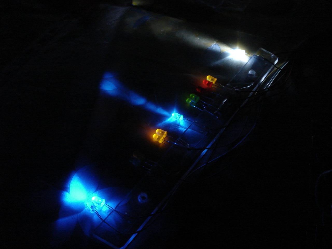
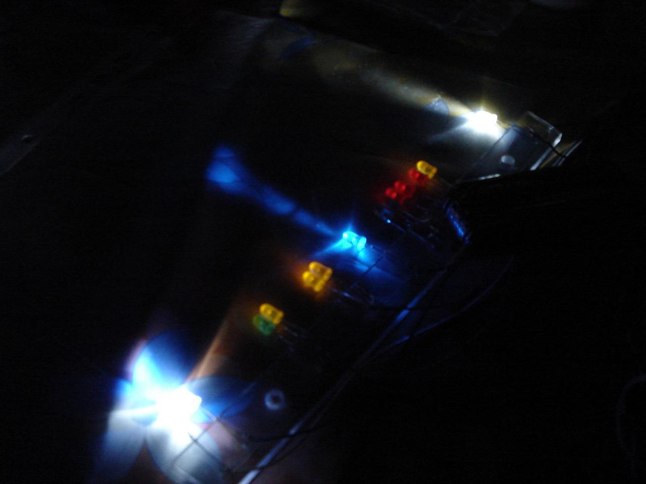
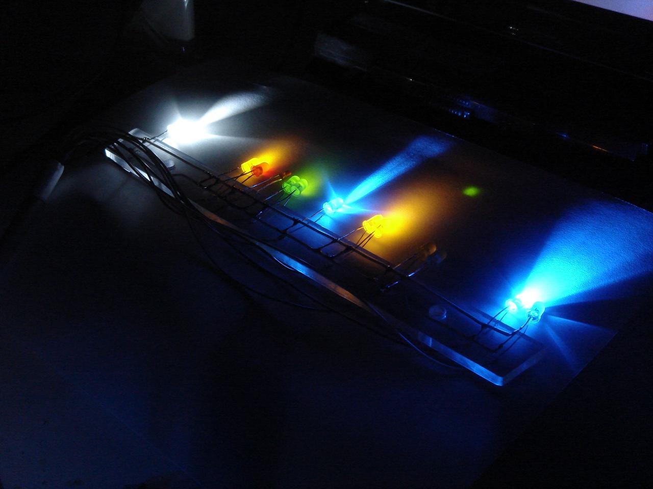
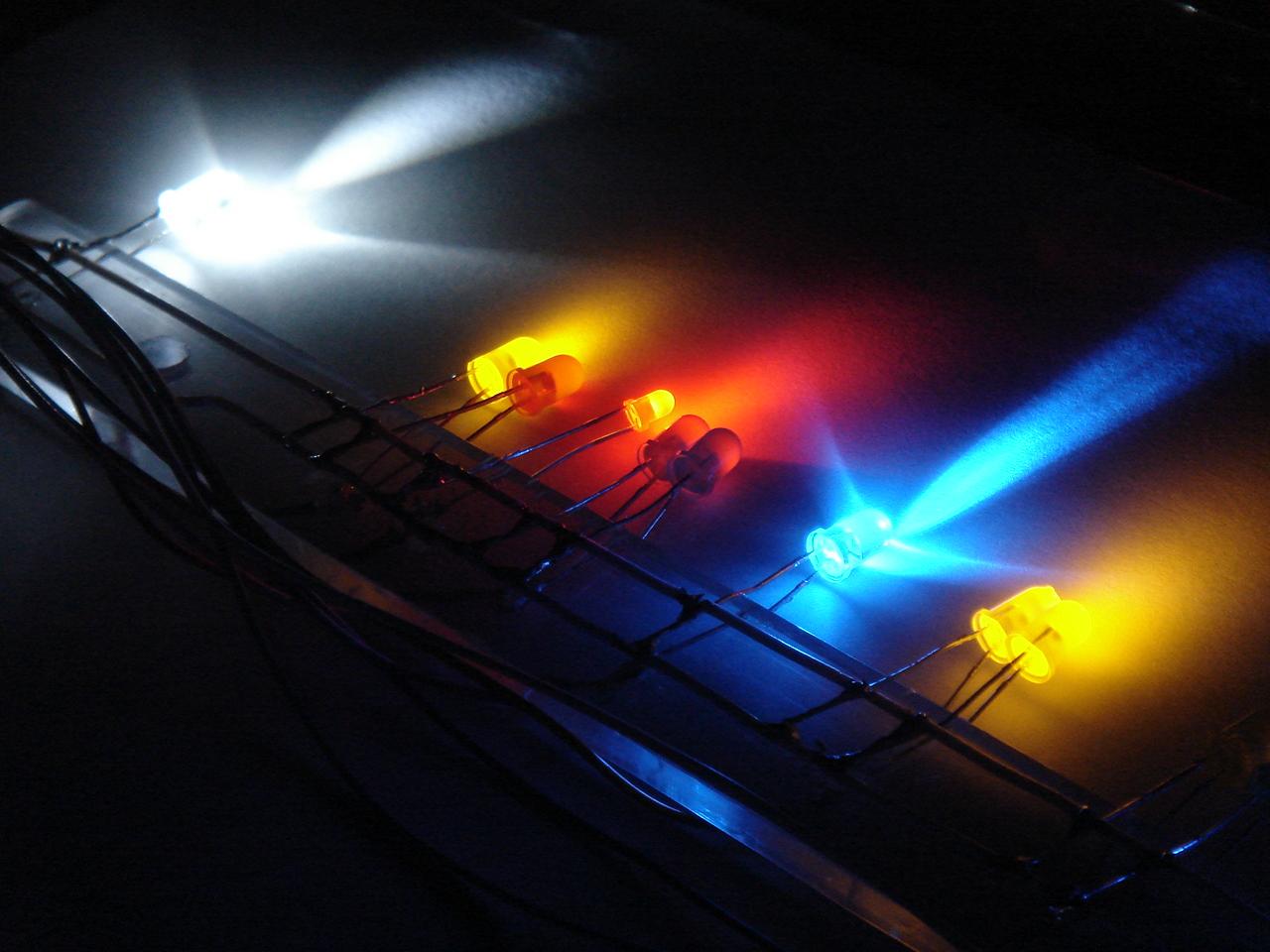
And now, this is a test of the sensors and their LEDs:
One of the sensor thin wires was broken, and I had to replace it:
I connect all the components of the sensors circuit:
I turn on the circuit, and…
…this is the video of the test!
(note that the sensors bar is below the policarbonate panel, so the sensors detect the fingers at a 5mm distance through the polycarbonate panel)
In order, I press:
– power switch (the white led, only for the press duration. The adjacent blue led is the power led that is always on when the PC is on)
– reset switch (green-yellow leds)
– mysterious device on/off (yellow leds)
– proximity sensor on/off (blue led)
– 5/12v fans speed (red led for 12v or green leds for 5v)
– audio on/off (red-yellow leds)
– lighting on/off (white led)
I soldered the single connectors to the sensors thin wires: it’s something I have not done until now because I was too scared to break them, these wires are very fragile…
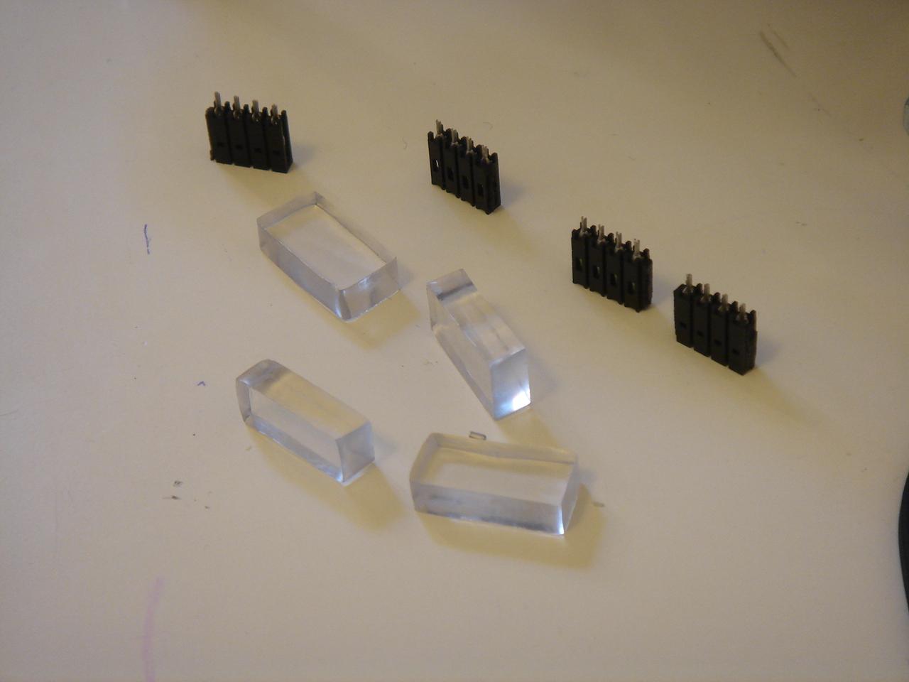
the sensors before this operation:
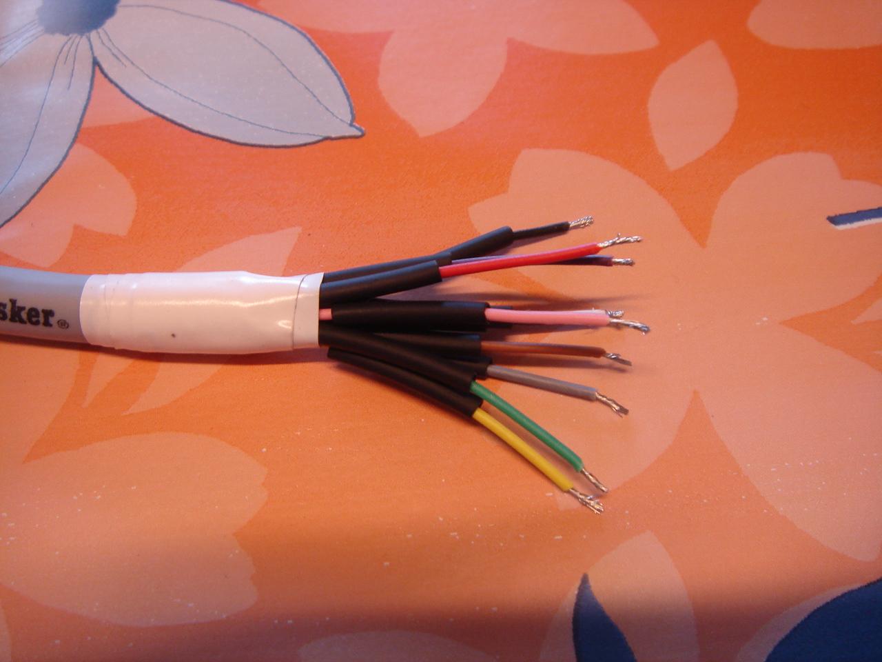
I cut the sensor wires at the correct length:
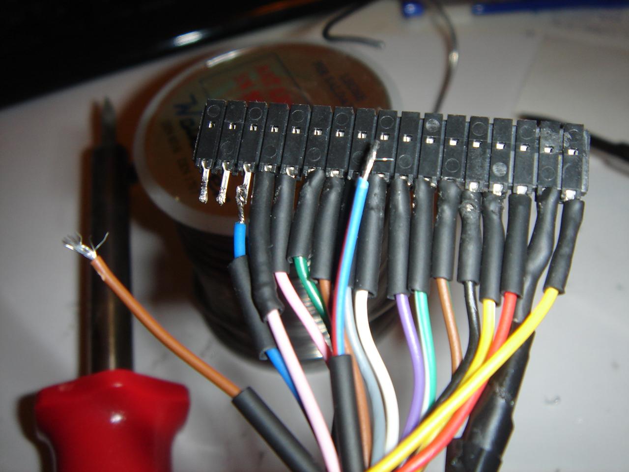
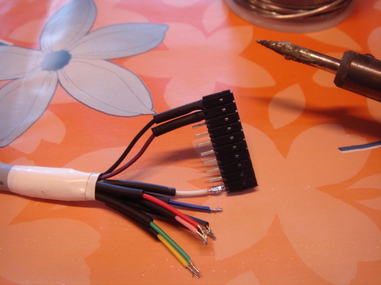
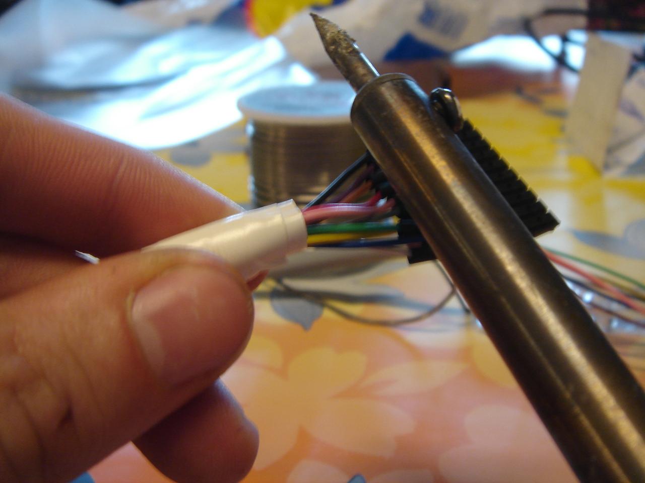
I start soldering the wires to the connectors:
…and done, luckily without any broken wire:

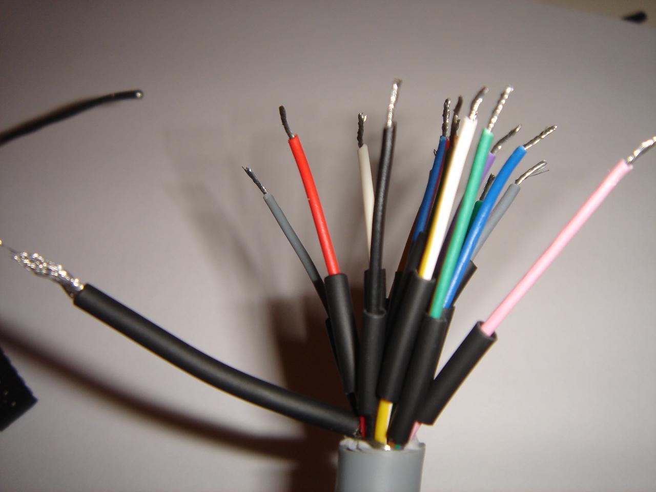
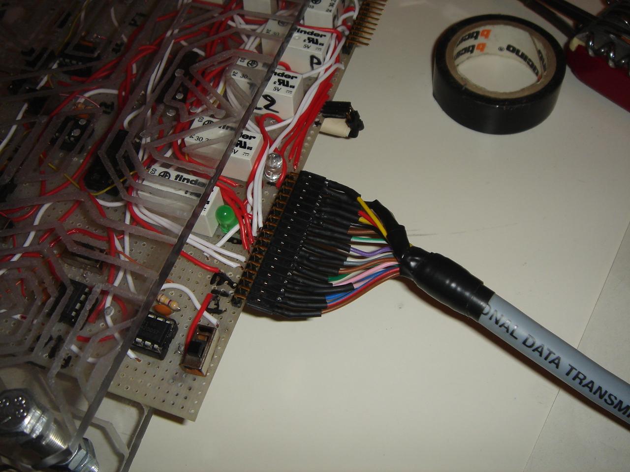
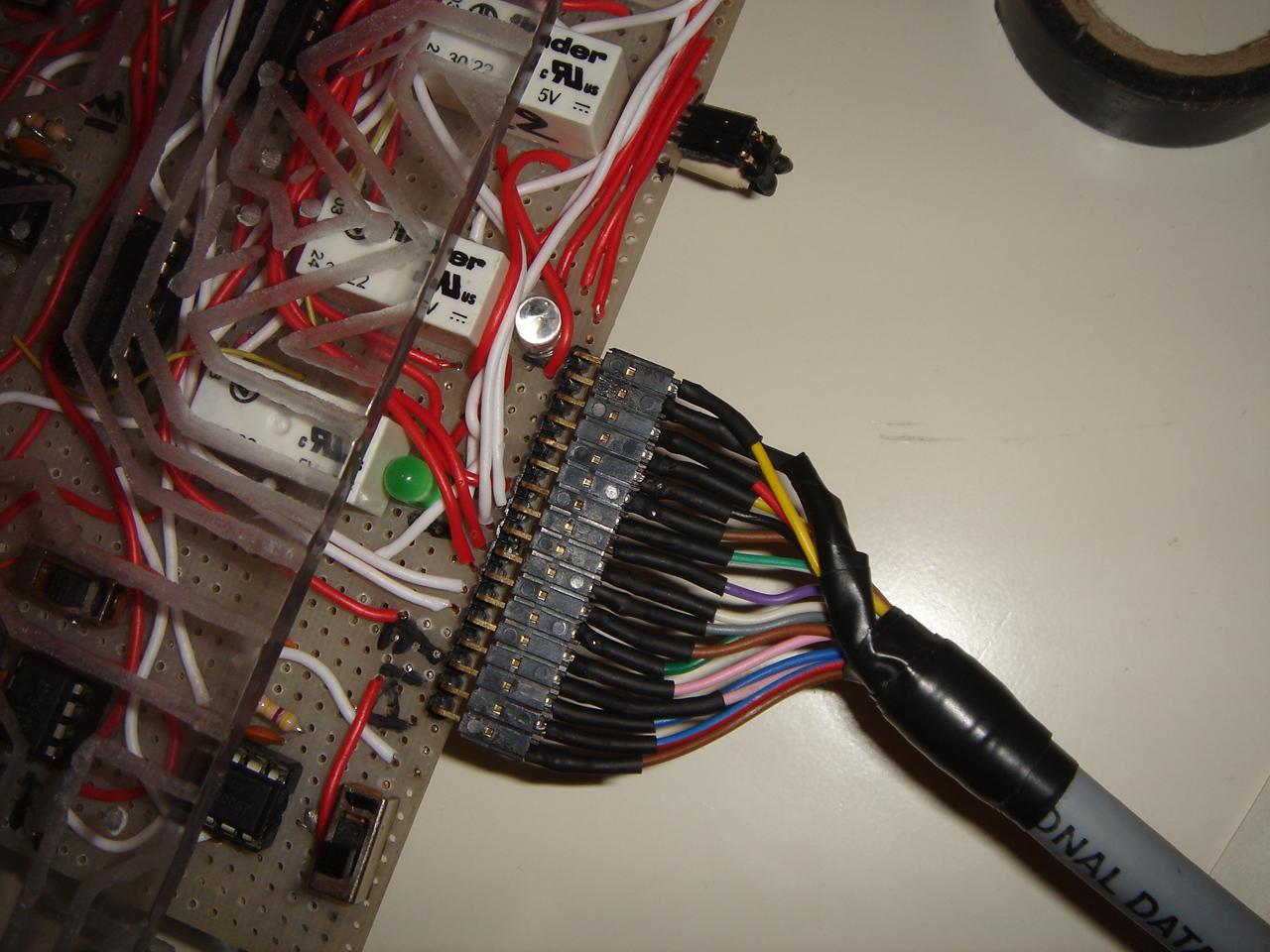
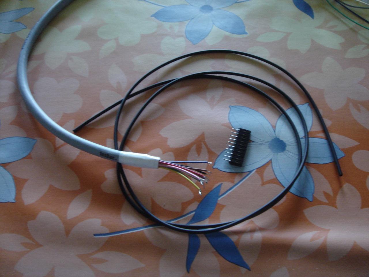
Then I soldered the 16-pole cable to the circuit connector (the bigger black wire in the pic is the metallic shielding of the cable, which I use as another wire because I needed 17 wires and not 16):
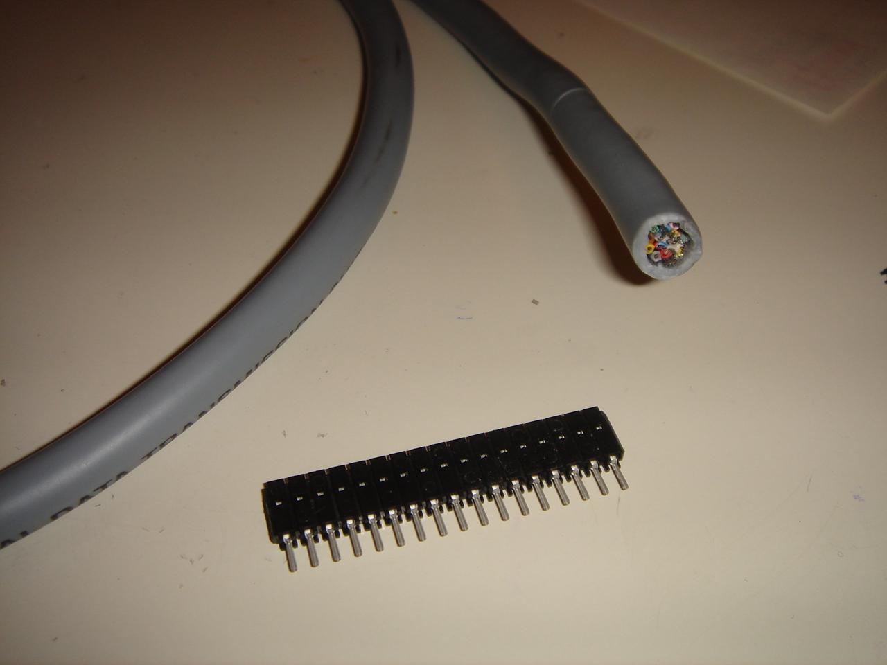
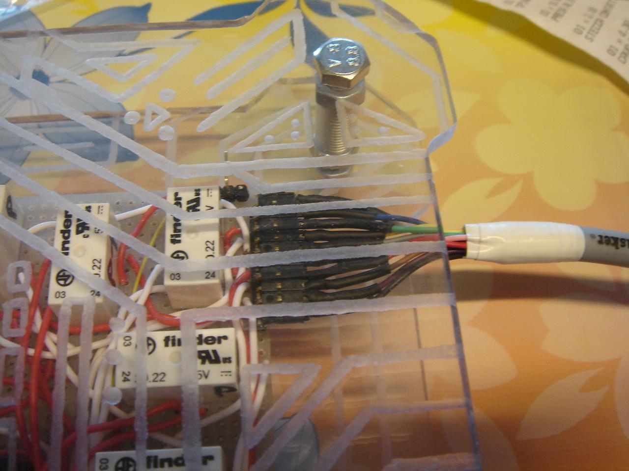
And this is the cable connected to the circuit:
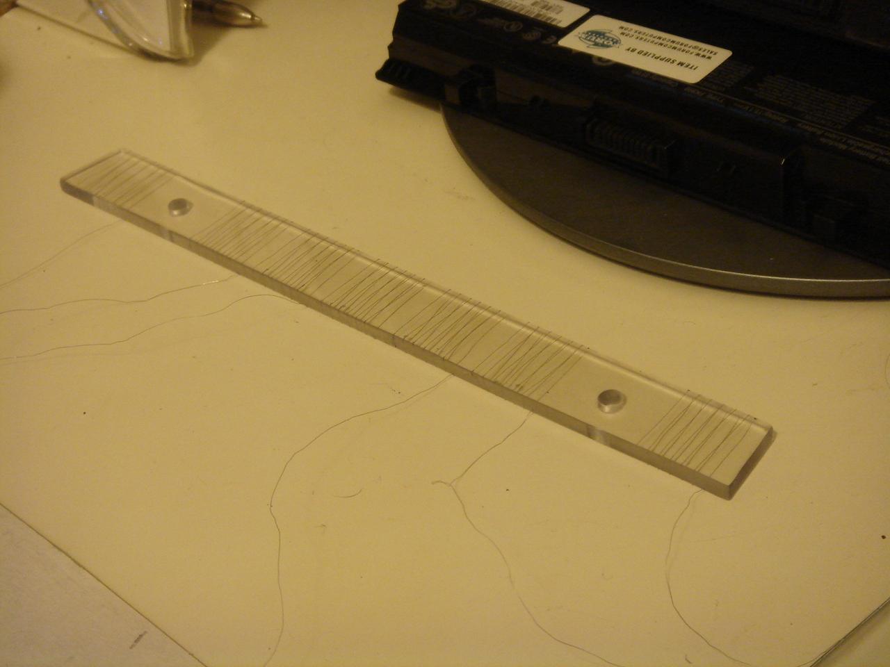
feedback LEDs bar for the touch sensors
Then I made the structure for the feedback LEDs, which will be placed under the touch sensors bar.
I needed a bar of polycarbonate like the one of the touch sensors:
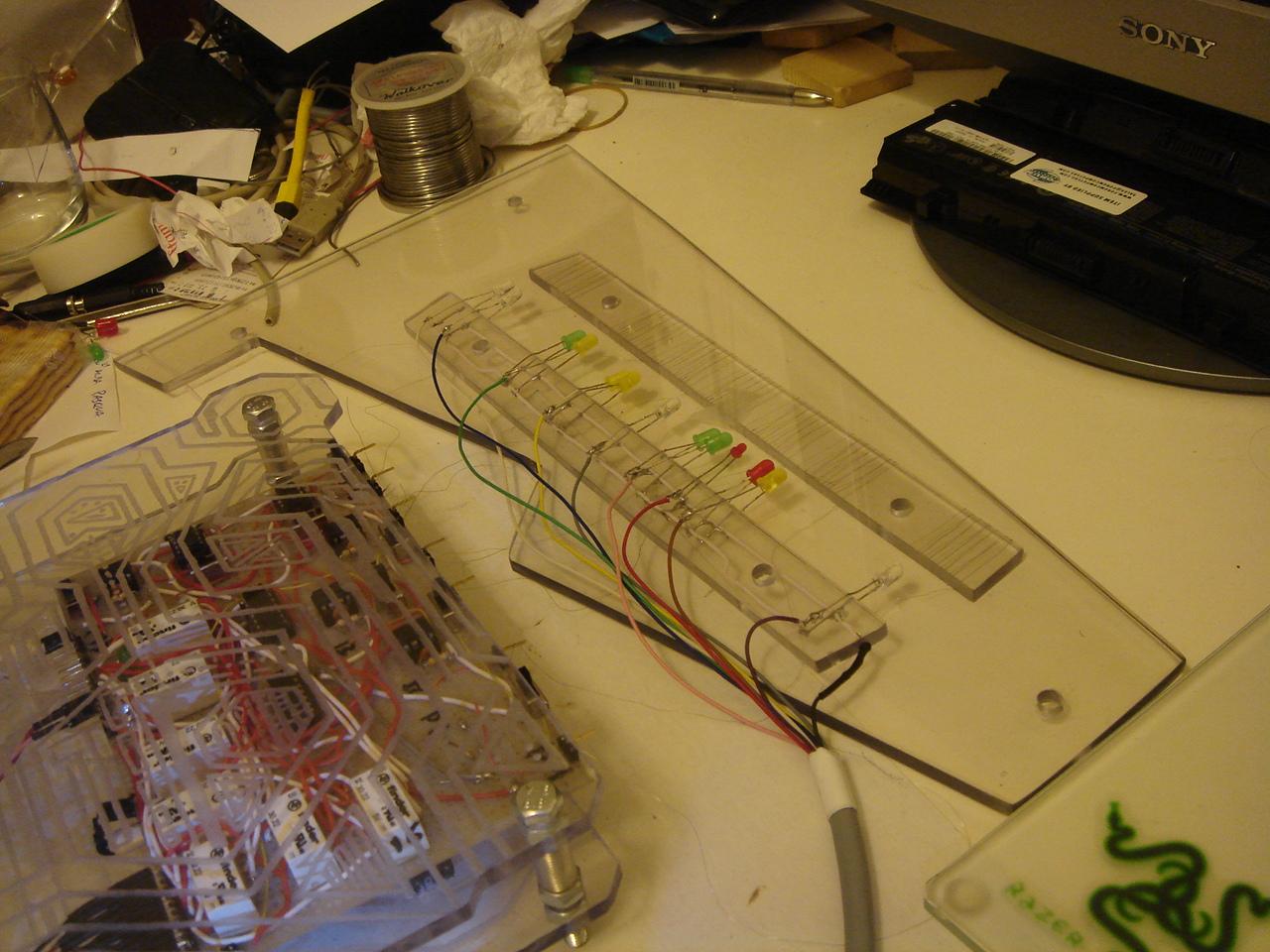
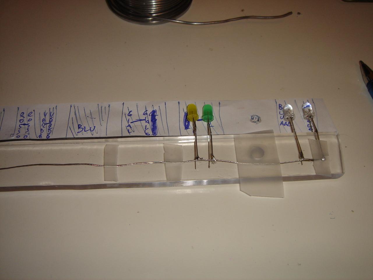
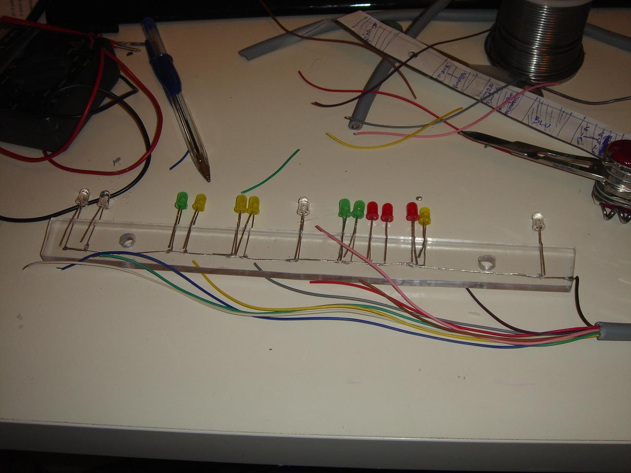
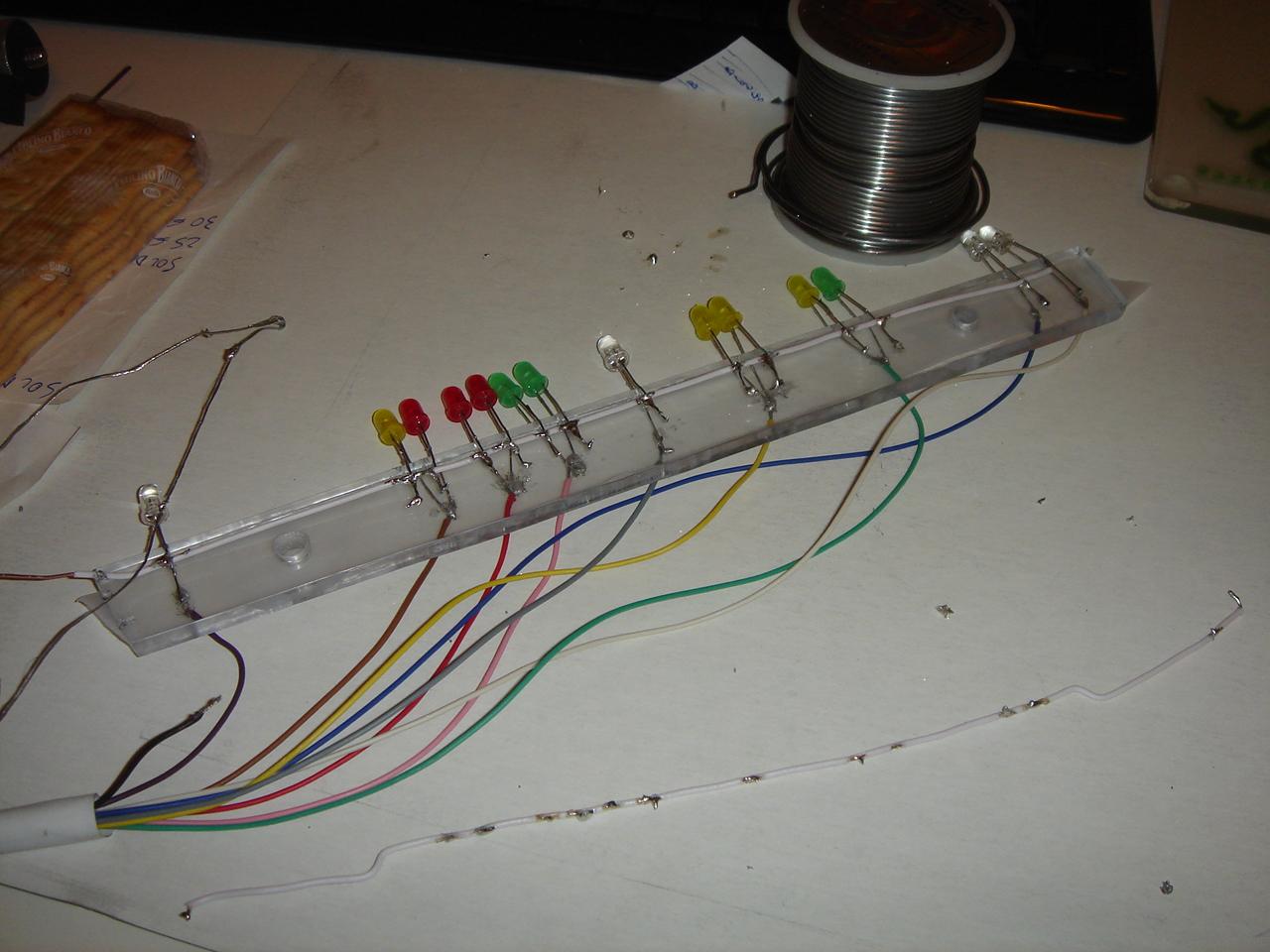
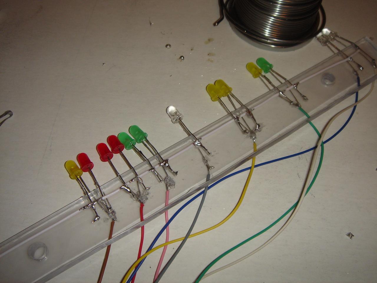
Then I decided the colors for the various functions, and I started soldering the LEDs on the polycarbonate bar:
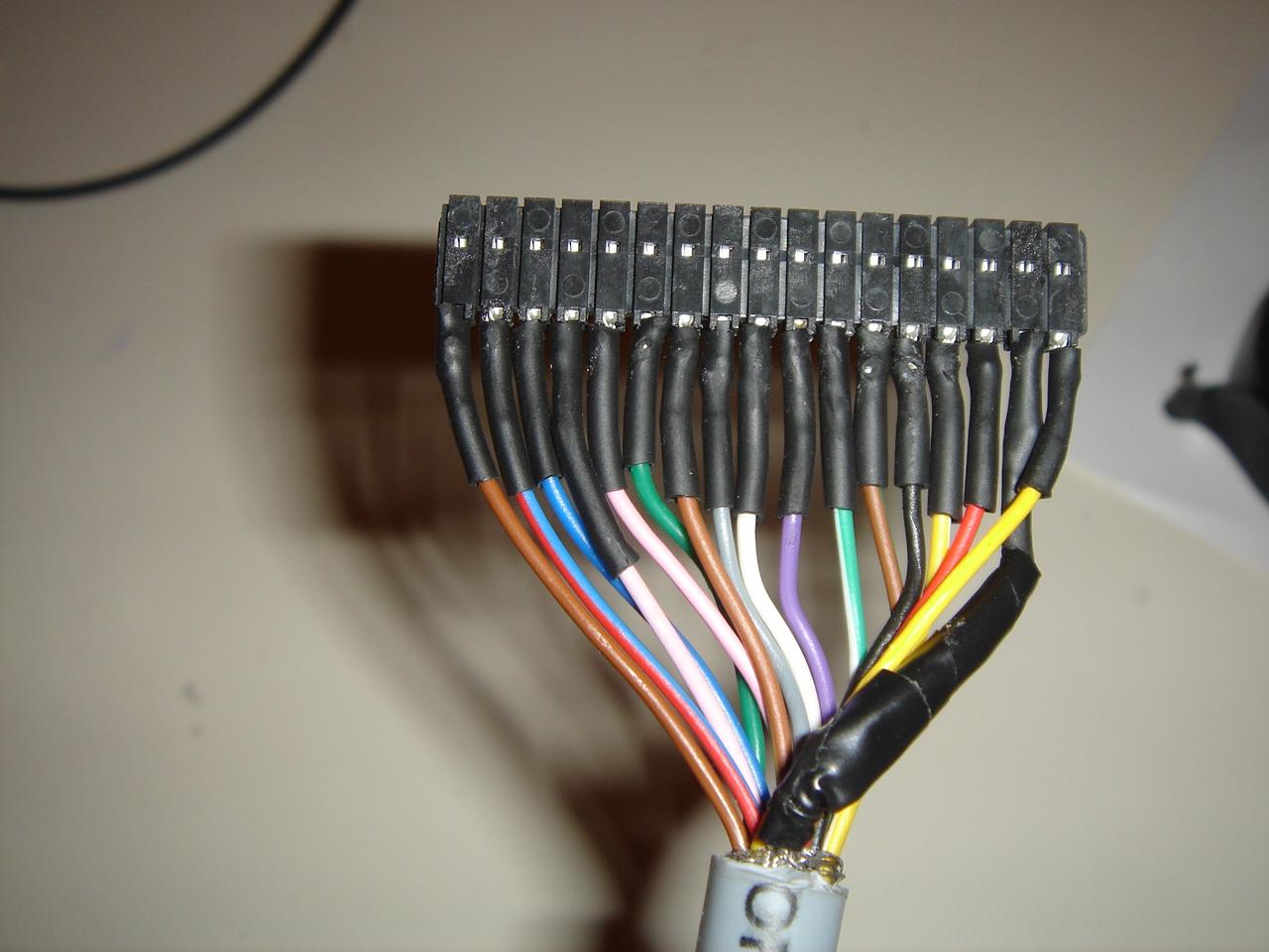
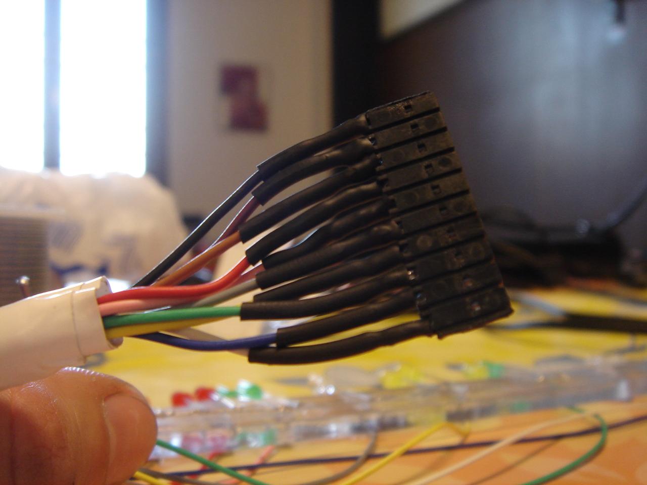
On the other side of the cables I soldered the 10-pin connector:
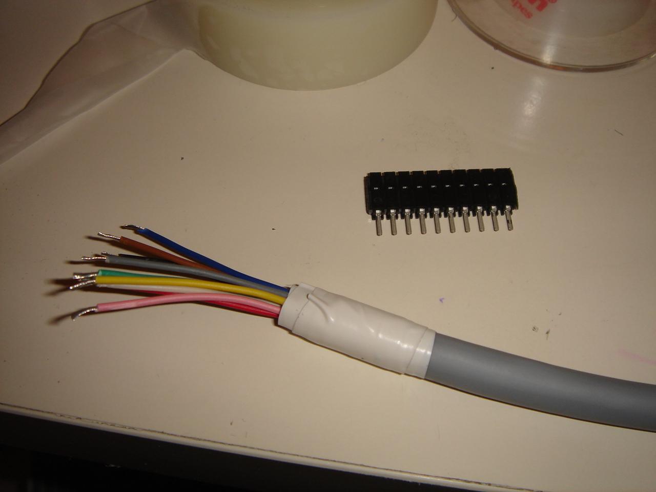
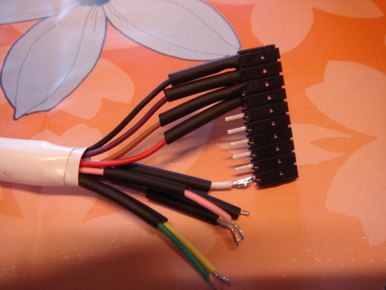
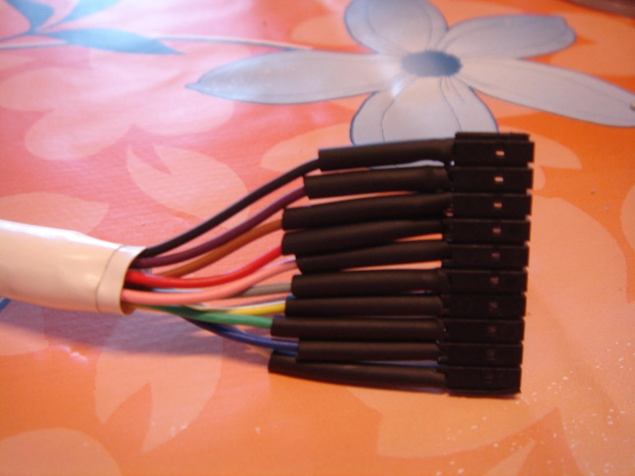
then I isolated the wires with heat-shrink sleeve:
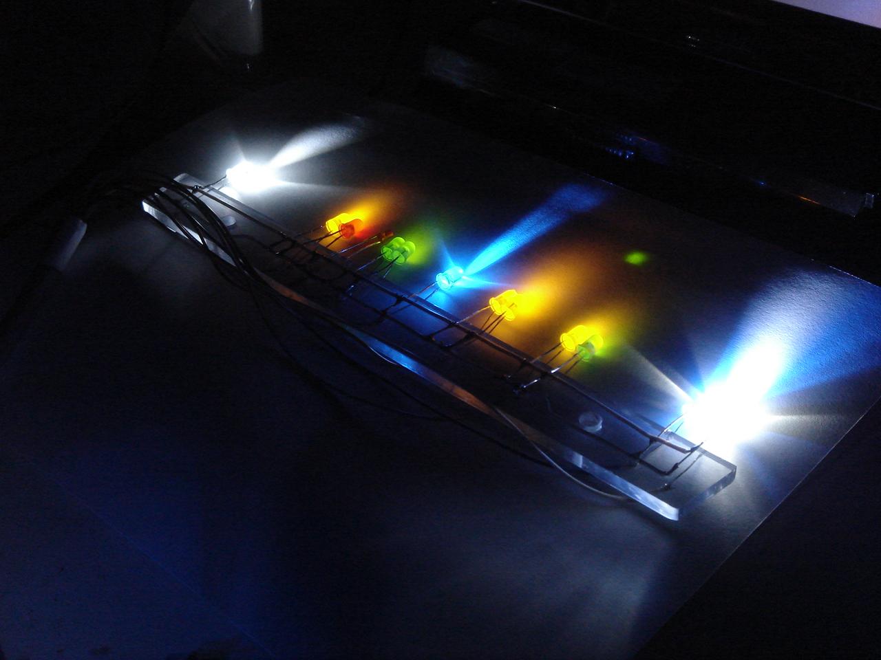
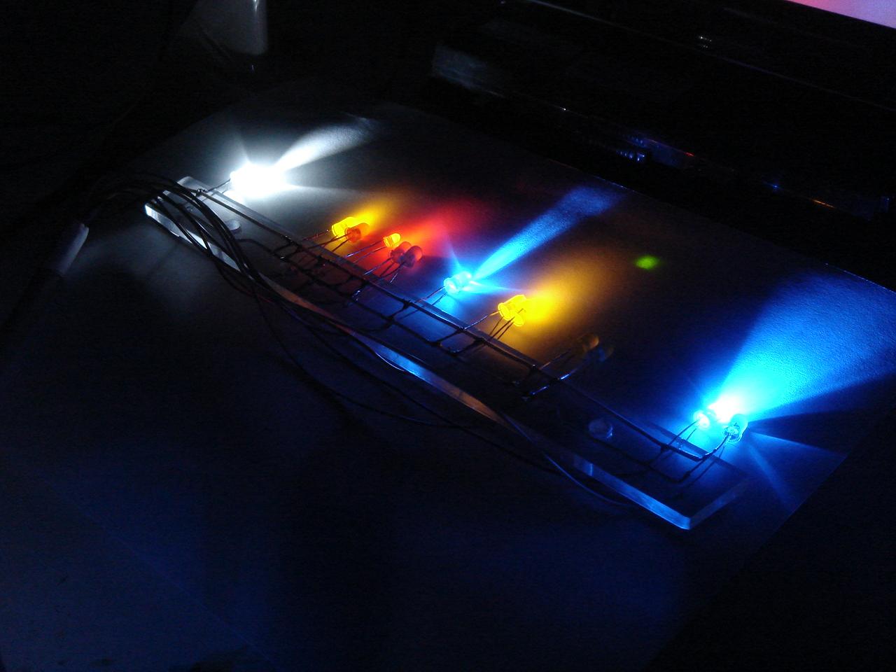
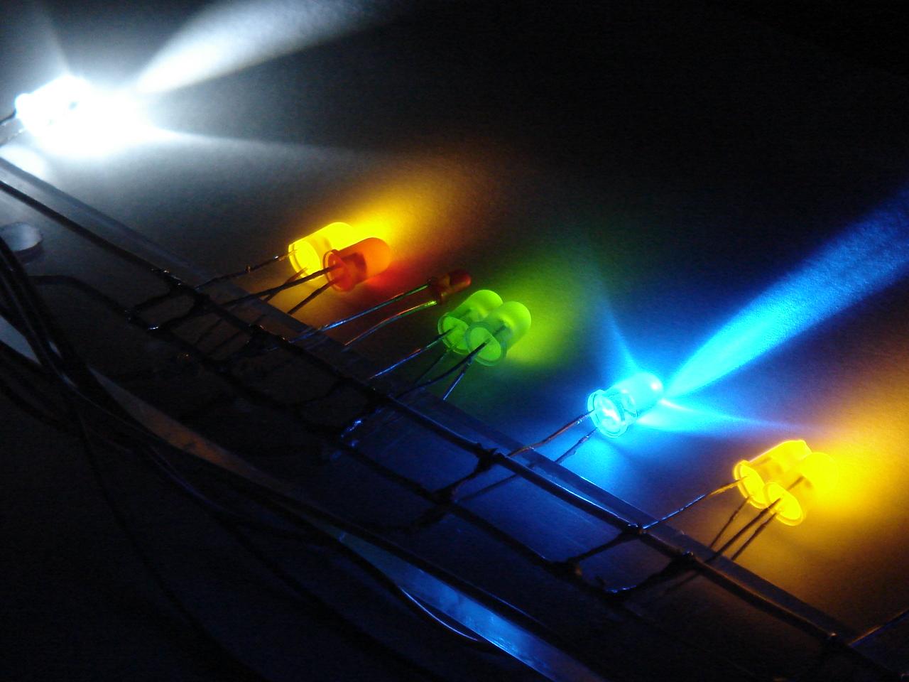
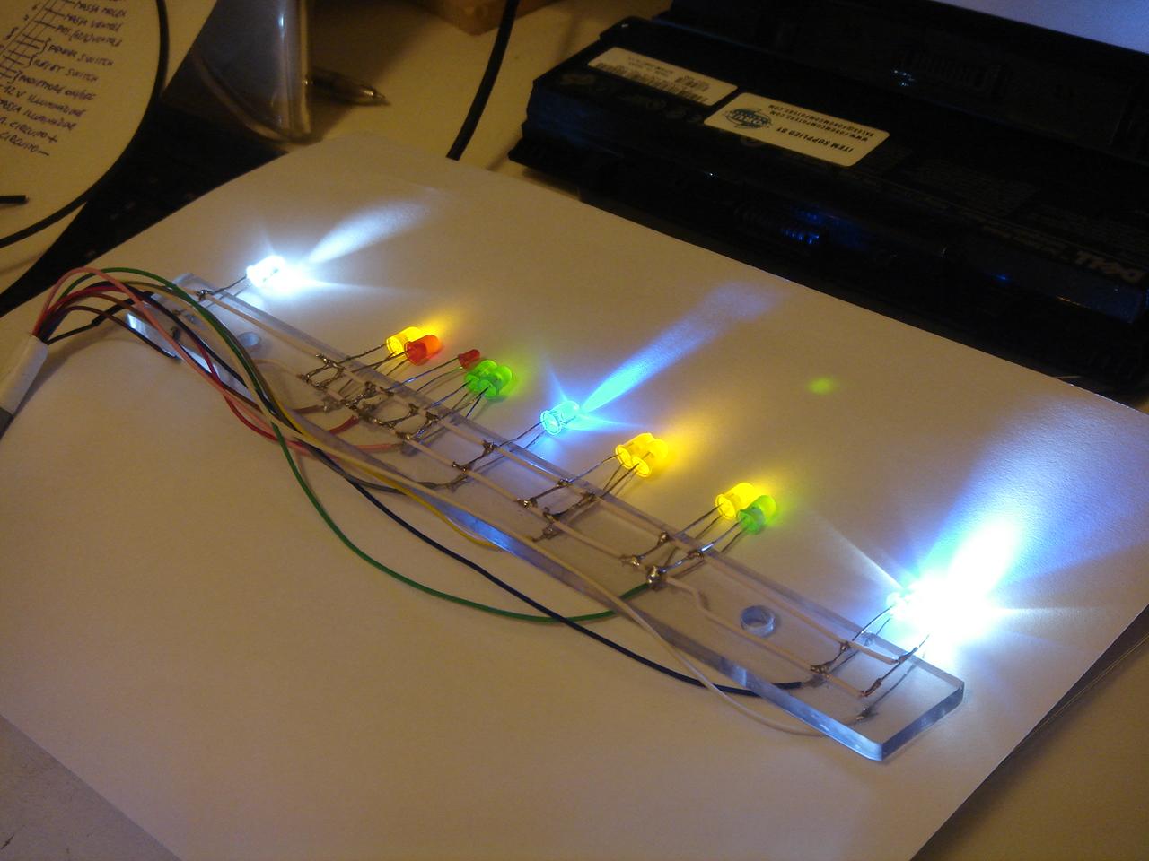
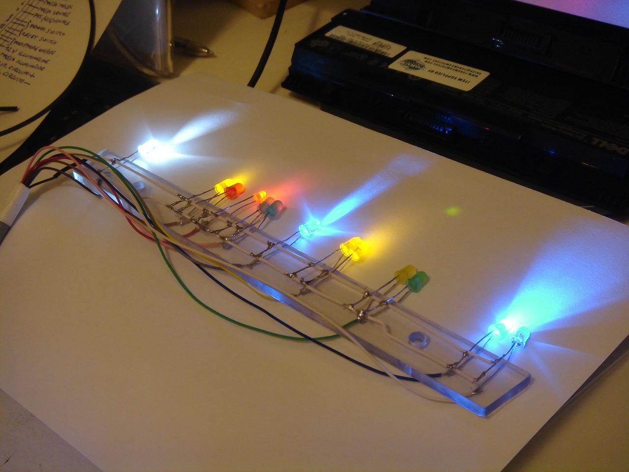
A LED test:
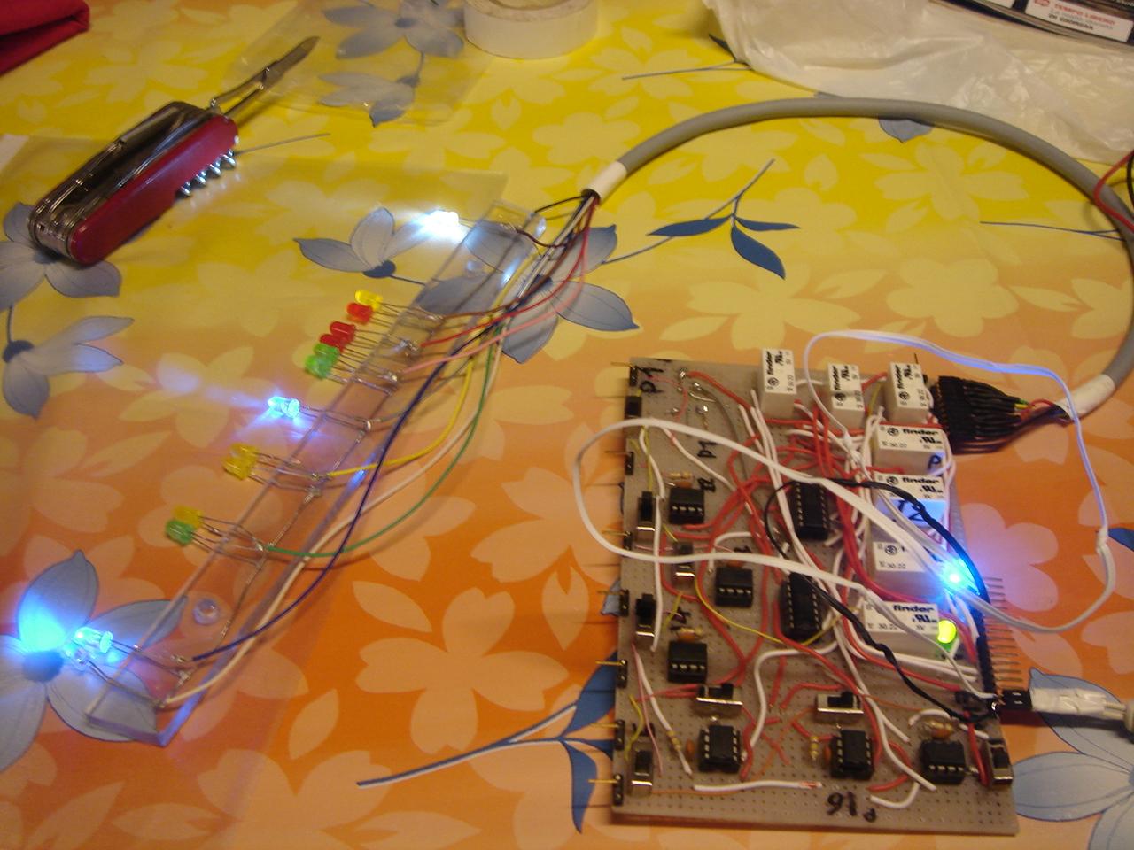
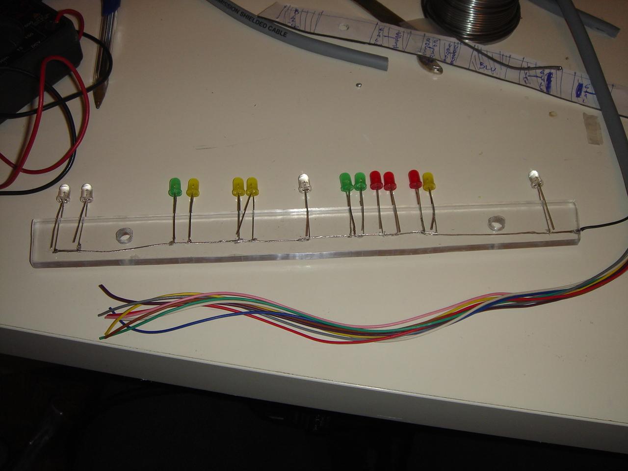
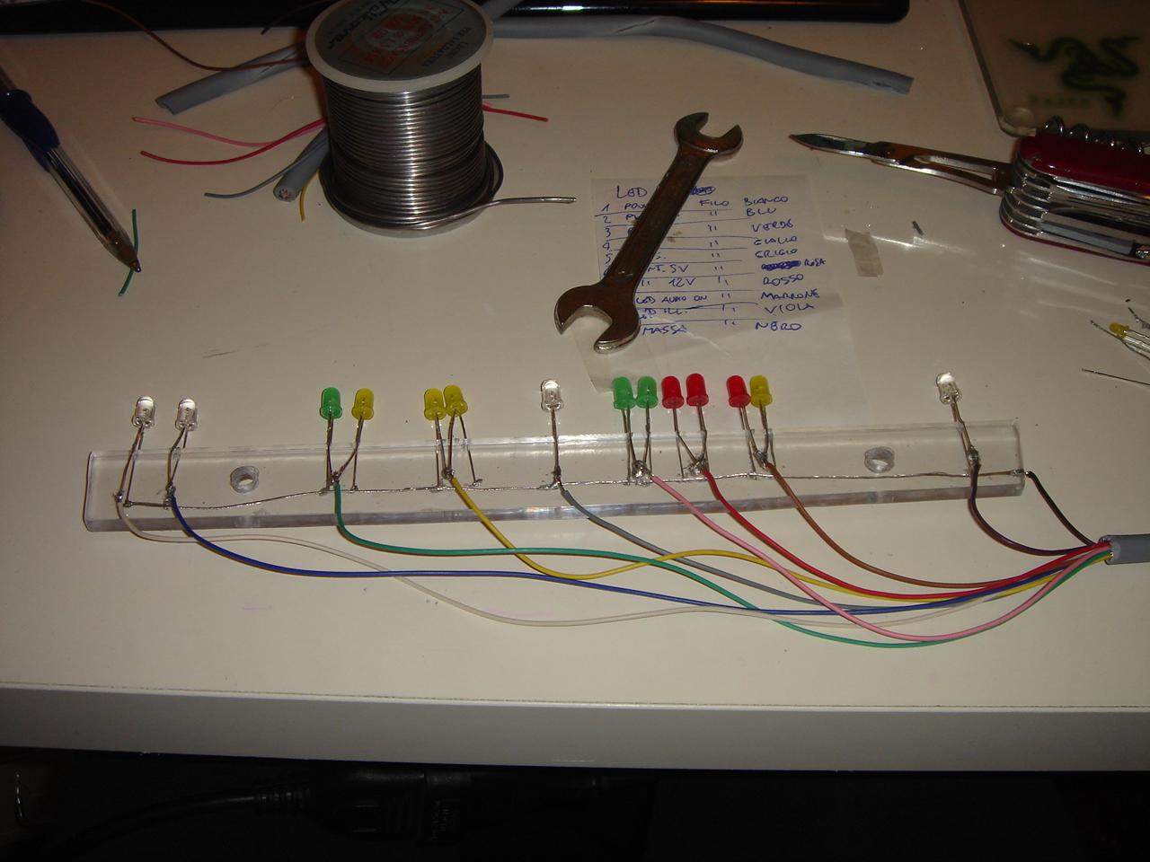
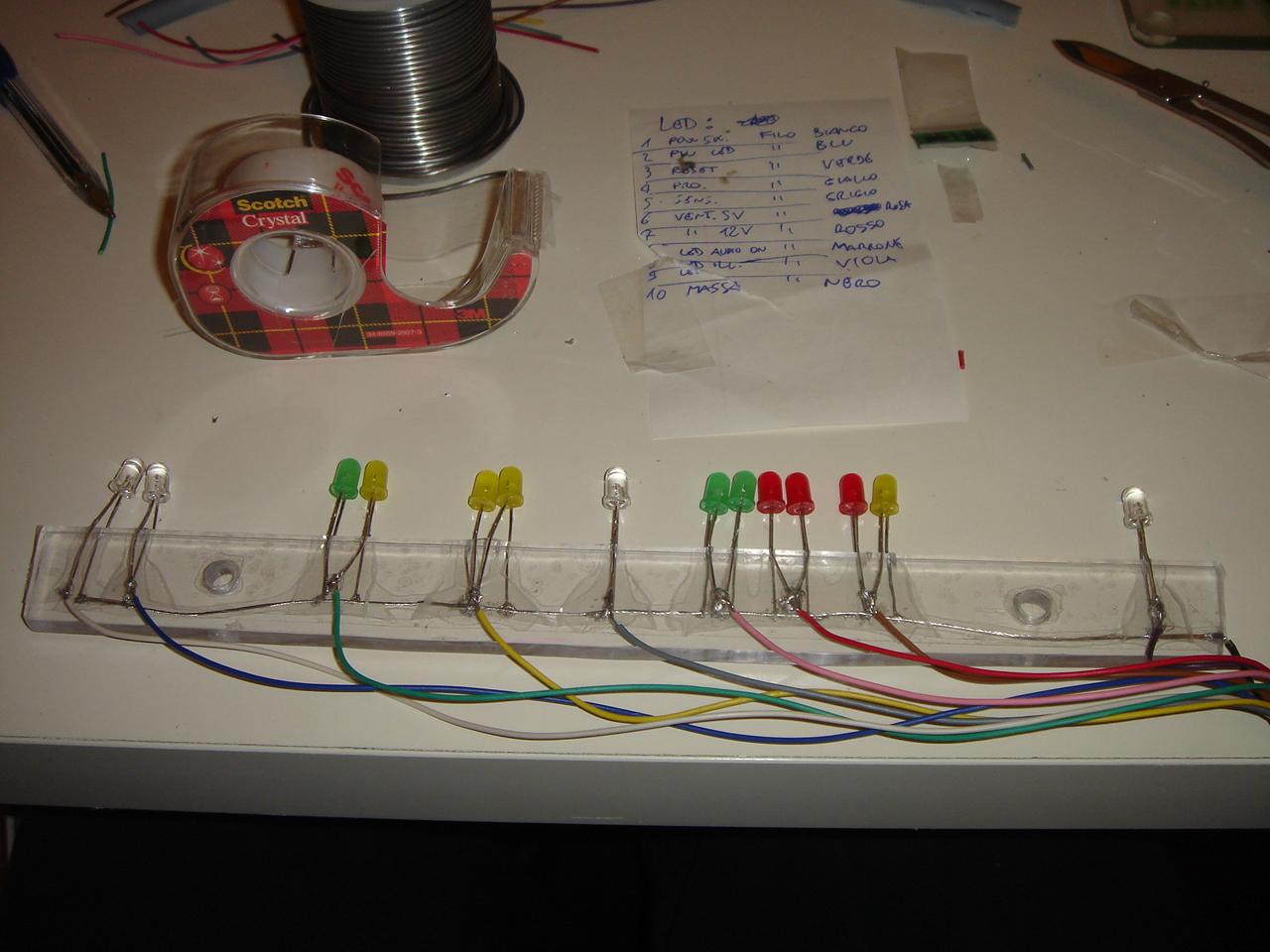
I was not satisfied with the result, so I modified the bar of the LEDs: I removed the wire that joined all the LED cathodes, and I replaced it with two rigid wires, made from a single thick copper wire, instead of a braid of thin copper fibers.
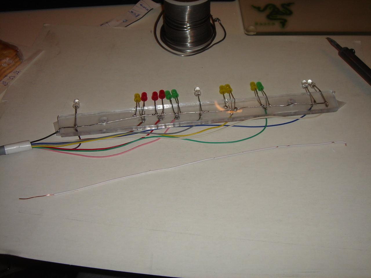
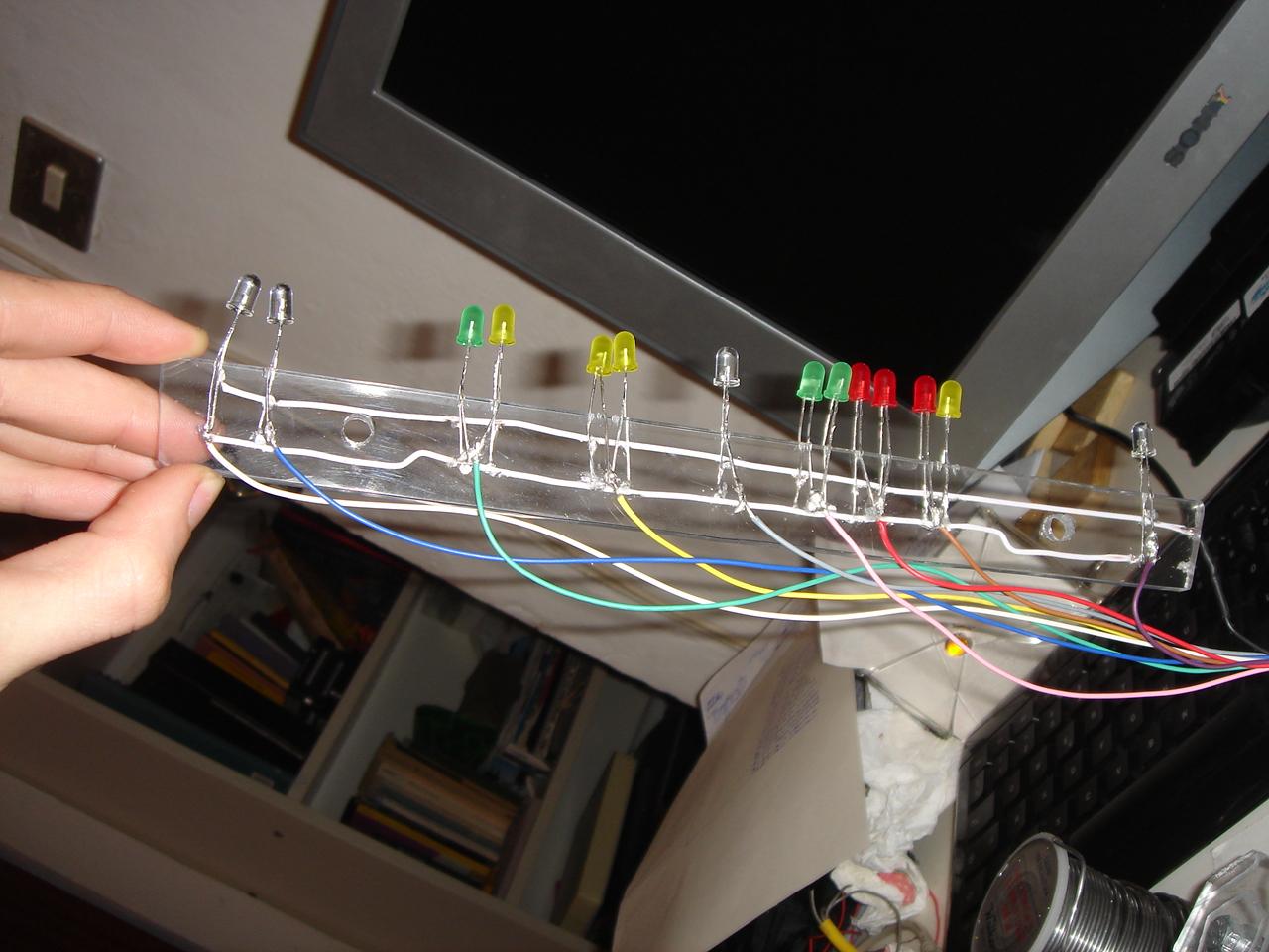
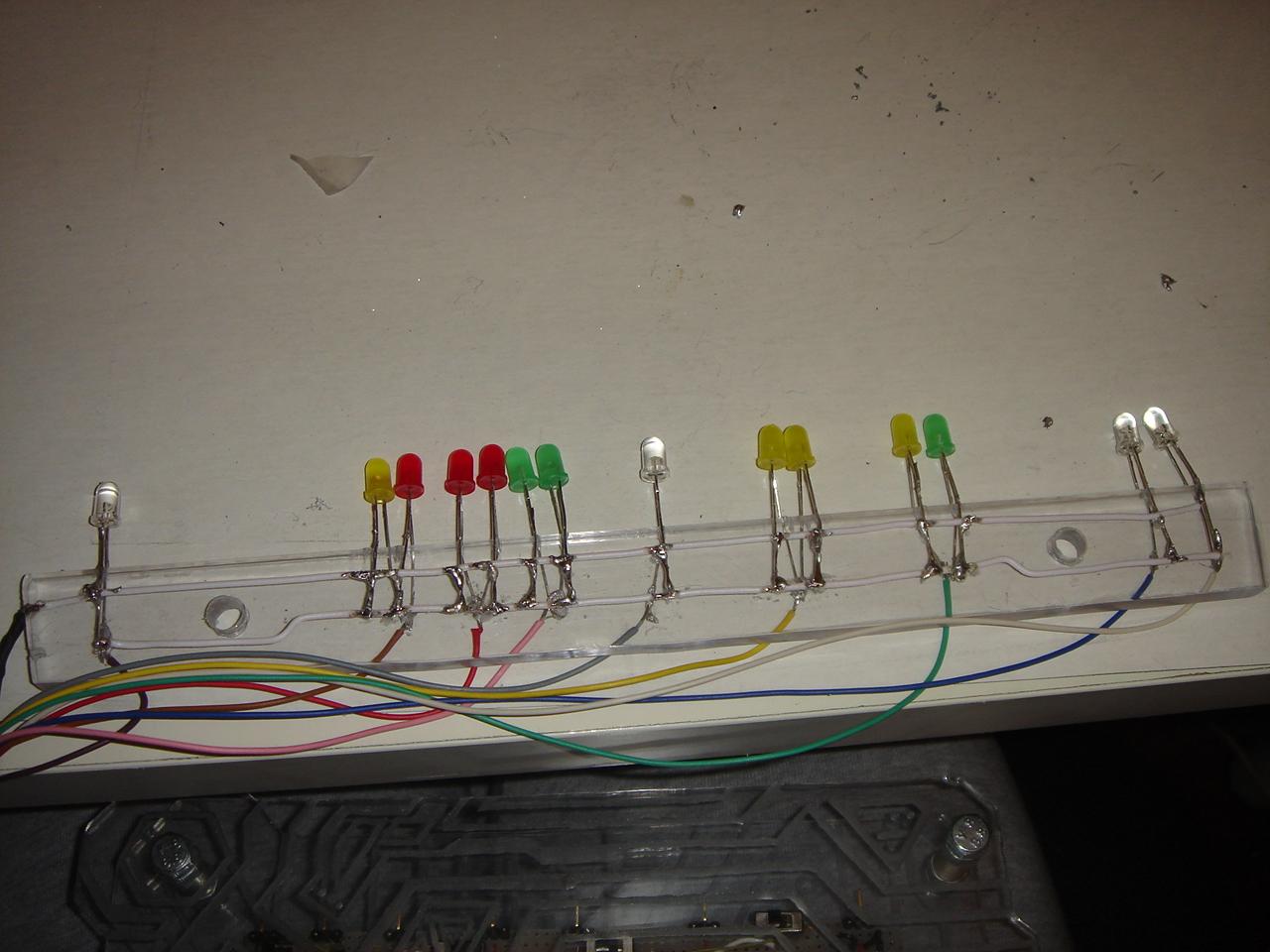
Also I replaced some LEDs that were less bright than the others, and this is the result (compared to the previous pics, you can see how the lighting of the LEDs is more homogeneous, while previously the light of the low brightness-LEDs was too weak):
completing the touch sensors circuit
The touch sensors part of the circuit was already completed, but in the circuit there wasn’t all the parts that link the relays to the various devices of the case (the diagram shown above), so i completed this part of the circuit.
These are the functions of the 7 touch sensors:
– power on
– reset
– “mysterious device” on/off
– proximity sensor on/off
– 5/12v fans speed
– audio on/off
– lighting on/off
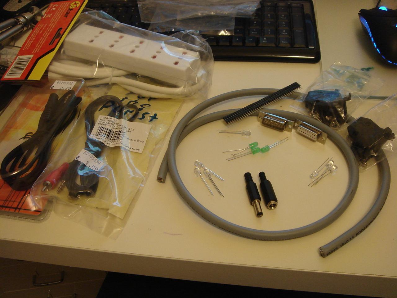
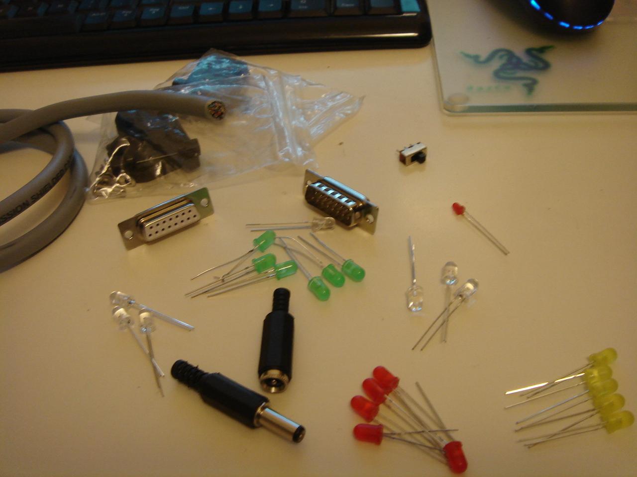
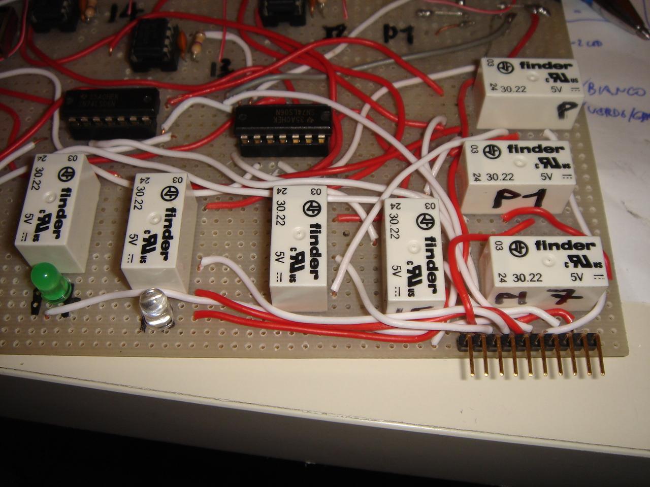
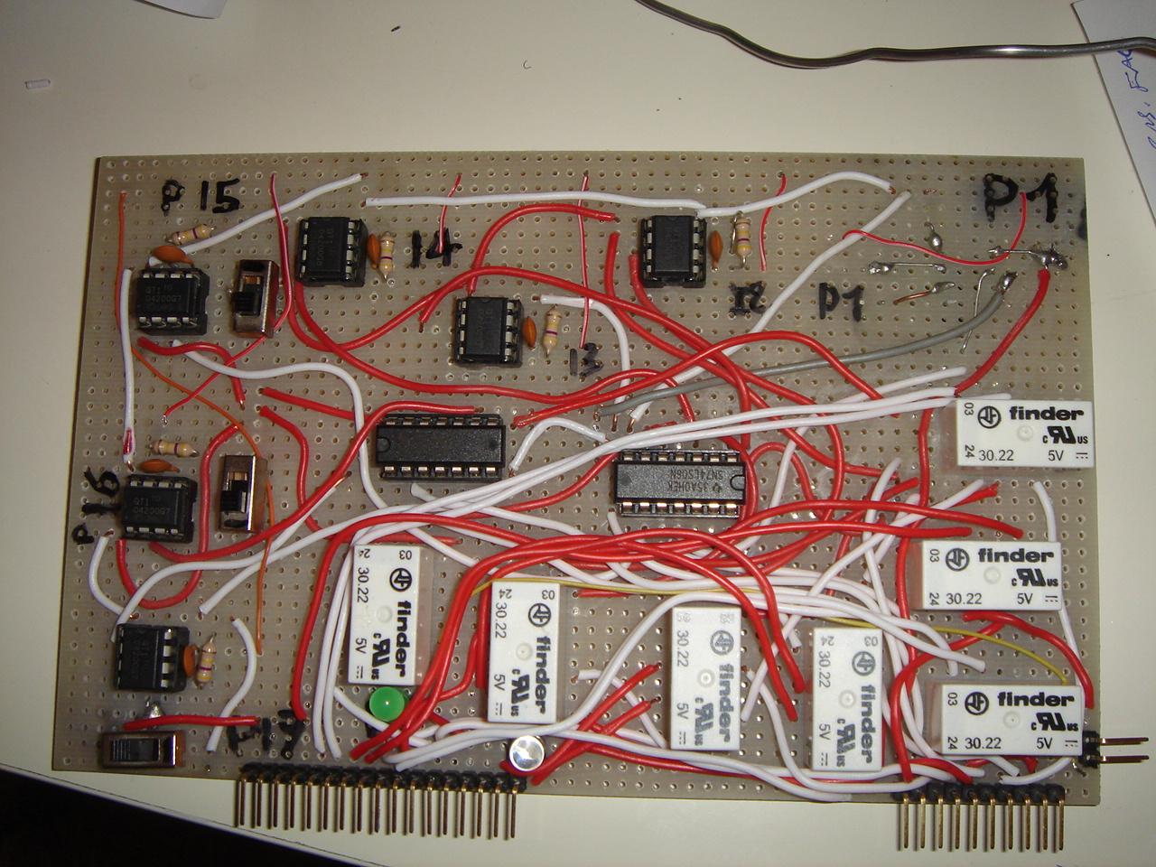
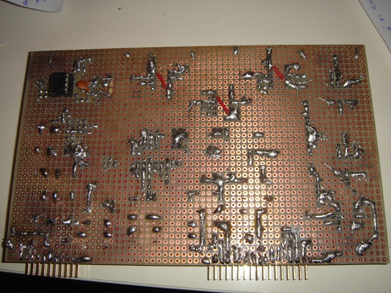
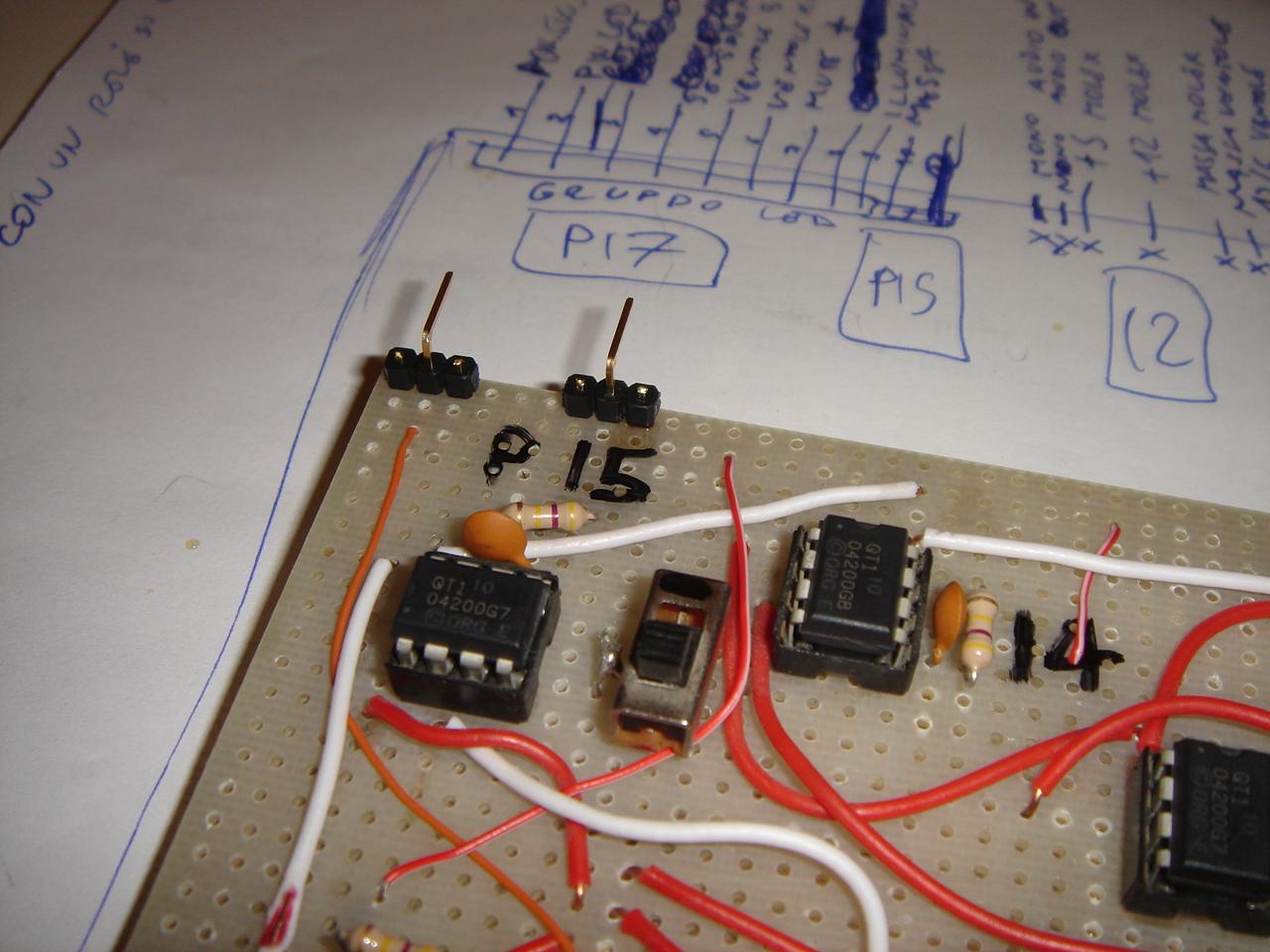
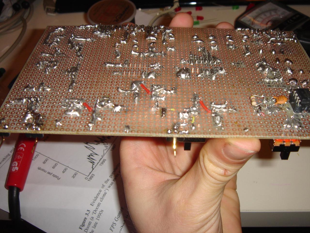
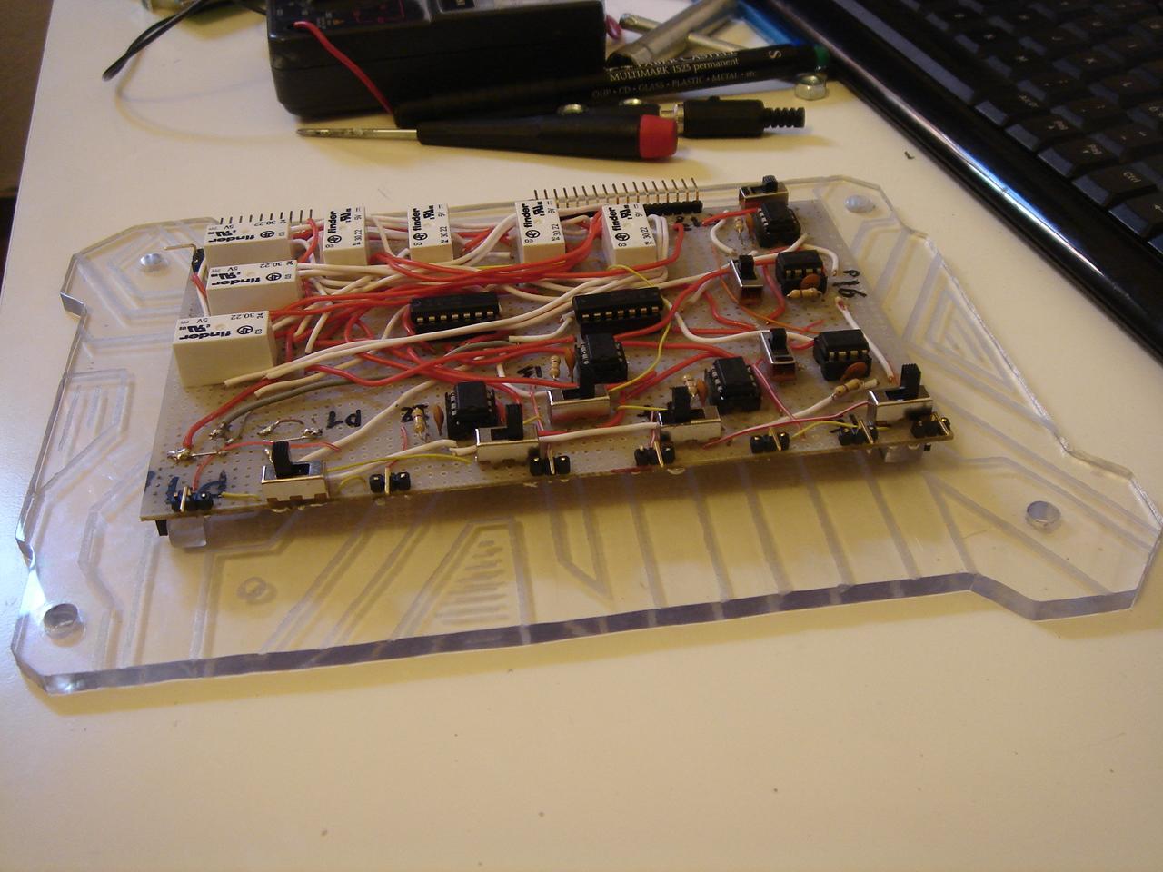
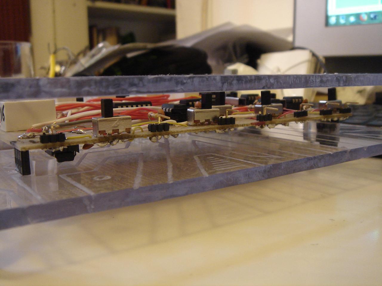
I bought some components, and I had left the circuit in this state:
I have done some tests for the proximity sensor (which is simply a touch sensor like the others, but with a bigger area)
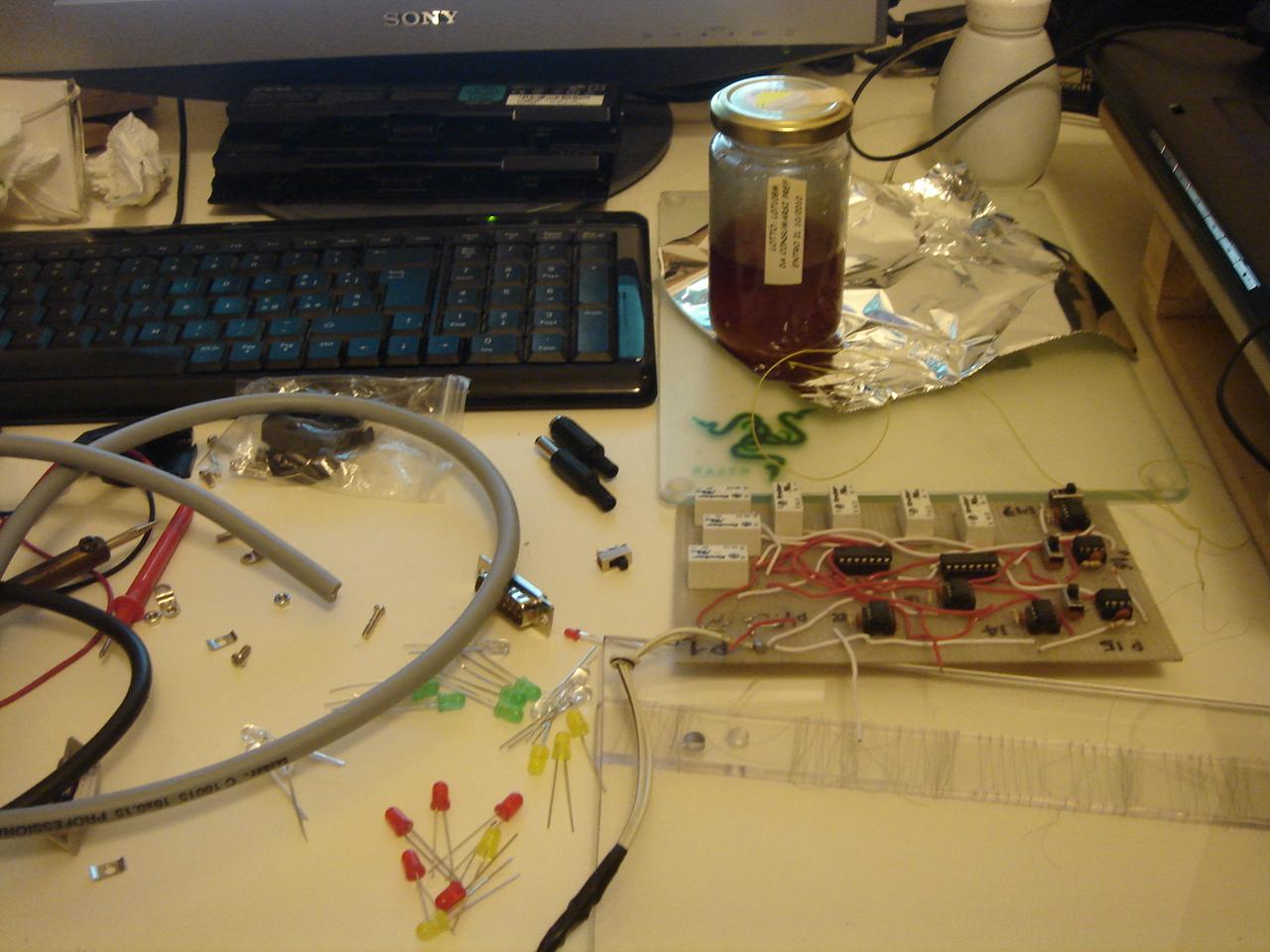
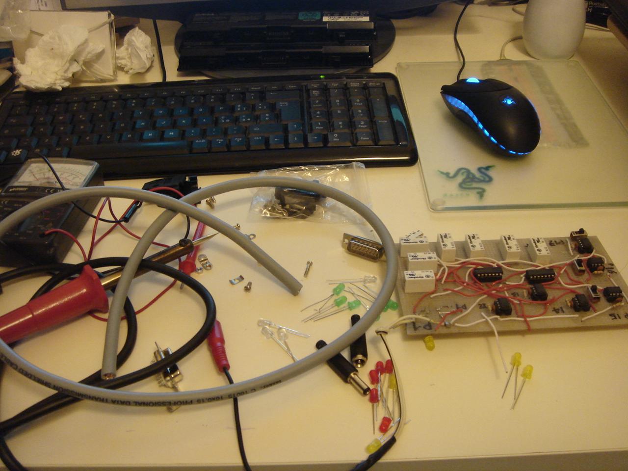
a photo of my electronic lab:

…and one of my workshop:
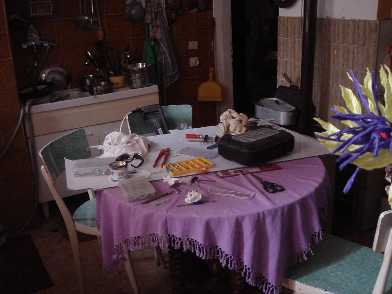
…very, very professional 😀 😀 😀
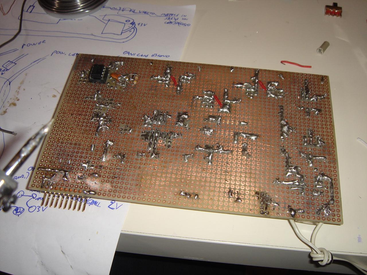
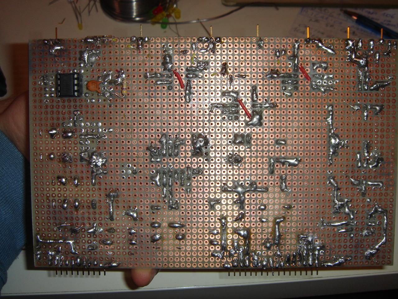
and now I start by soldering the part that manages the feedback LEDs for the sensors:
Then, i soldered the contacts socket for all the connections with the devices.
(to reduce the number of cables, I took a 10-wires cable for the feedback LEDs, and a 17-wires cable for the devices, so only two big cables will be connected to the circuit, hiding the fact that the circuit needs 17 connections with the components of the case, and 10 with the feedback LEDs).

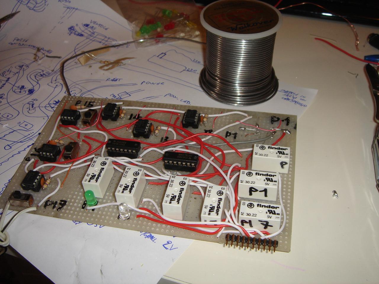
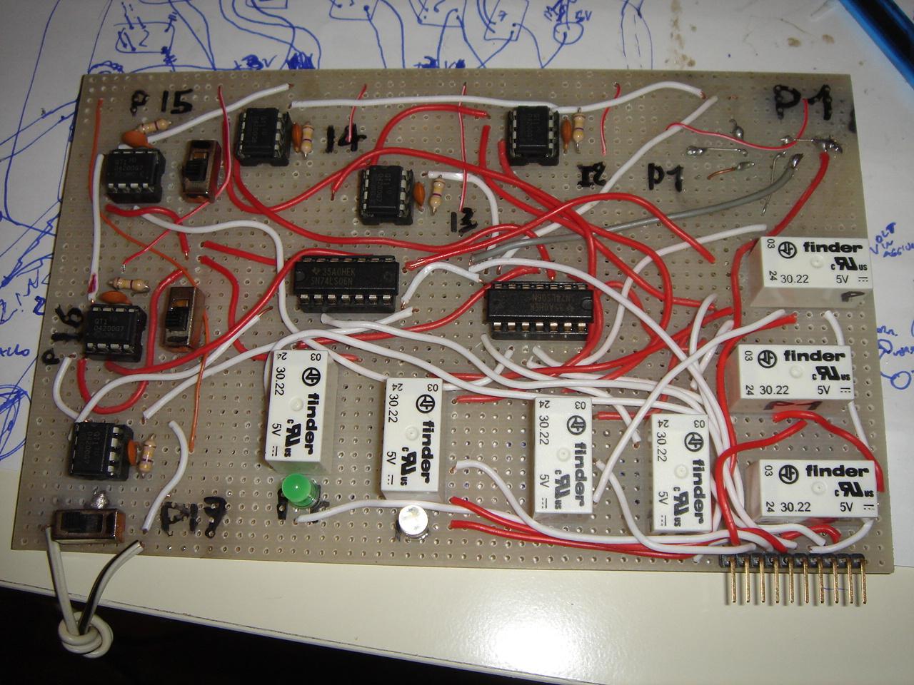
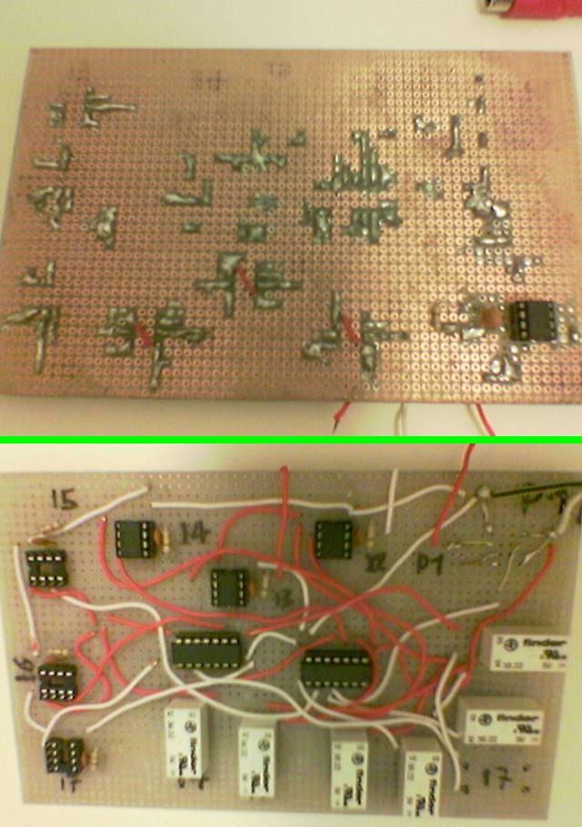
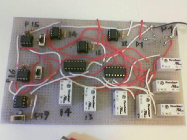
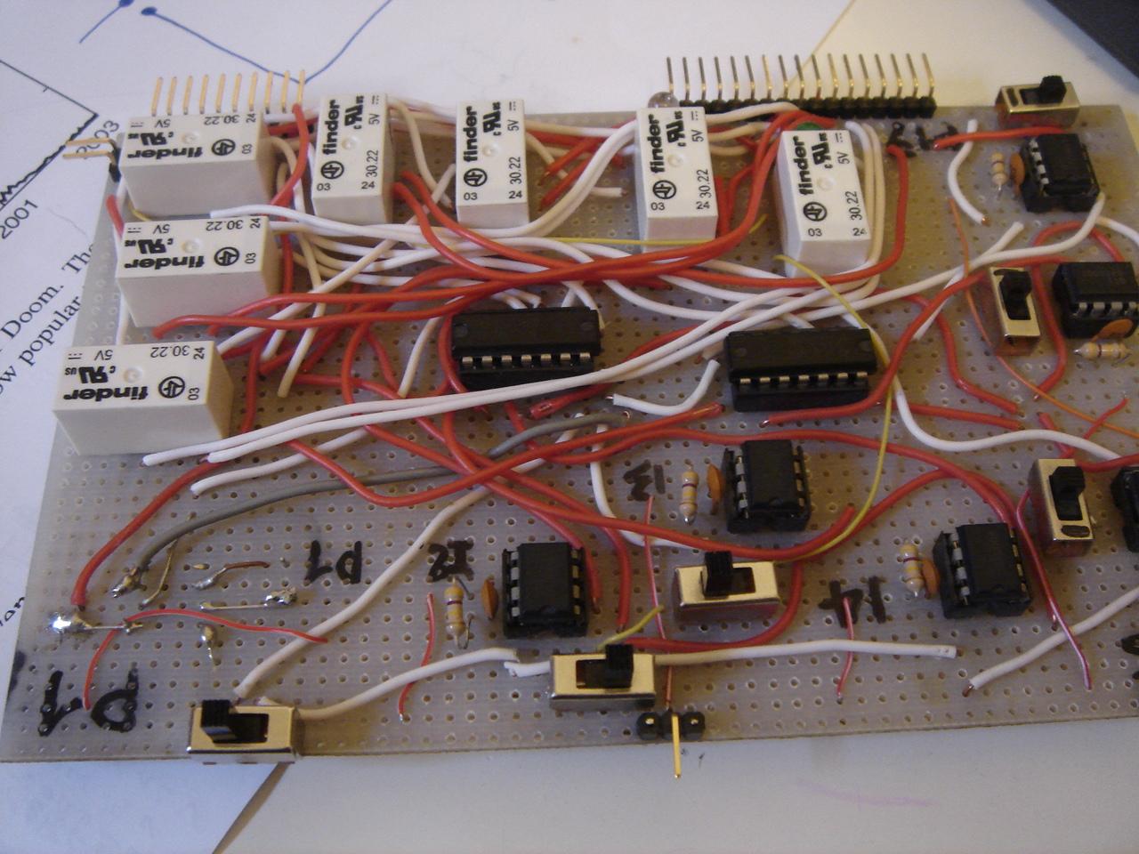
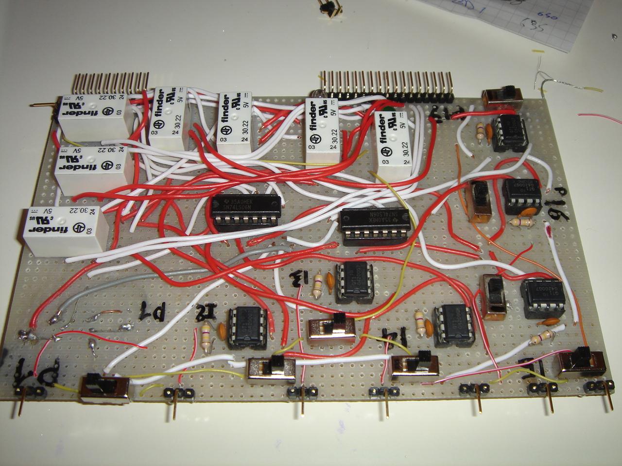
The wires have increased a lot. For a comparison, this was the circuit before this last job:
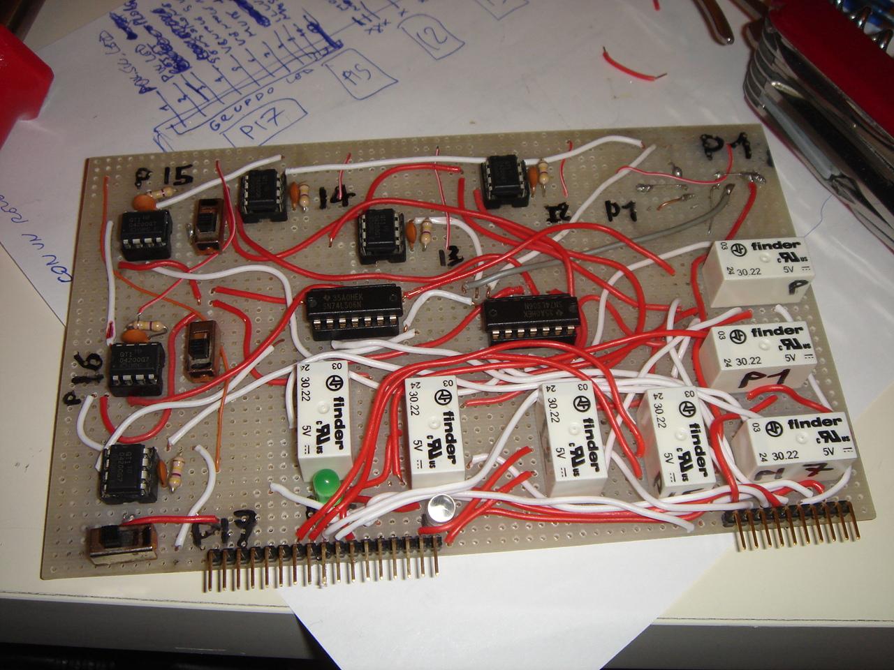
Then I started to solder the single contacts for the touch sensors and for the proximity sensor.
The proximity sensor will be on the left side wall of the case, and detects the proximity of the hand (at 2-3cm of distance) instead of the touch of the finger.
It can be activated and deactivated by one of the touch sensors.
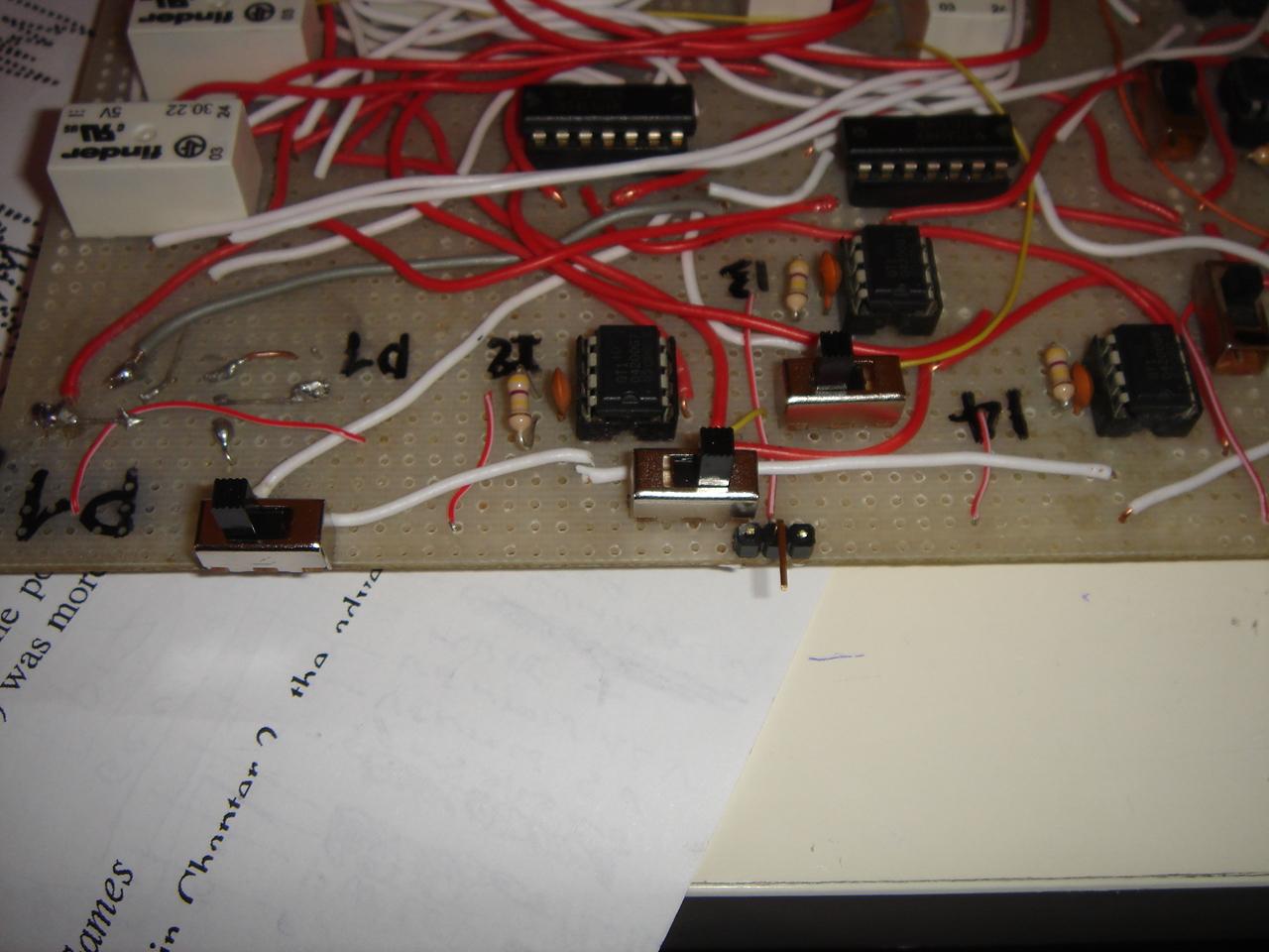
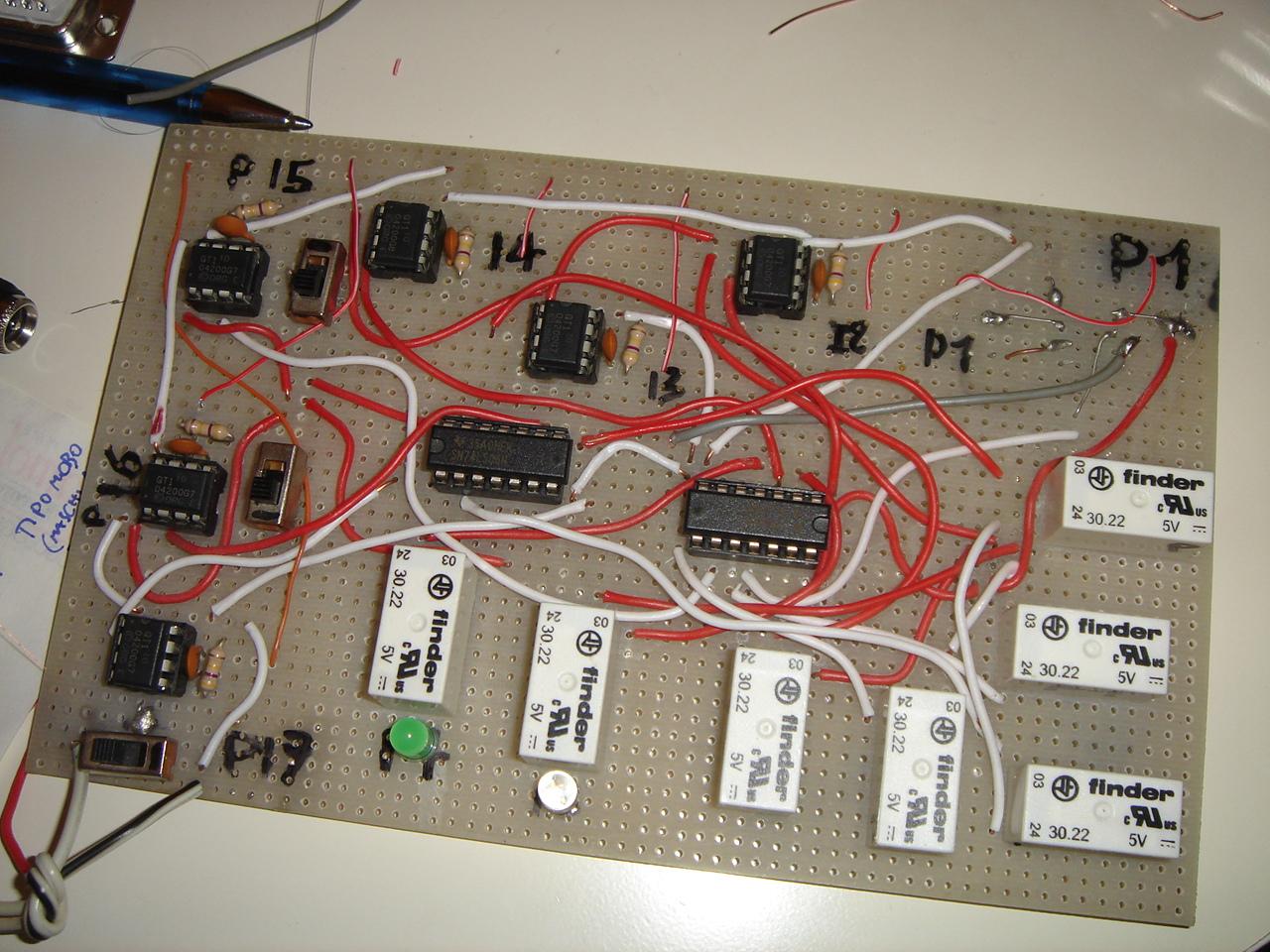
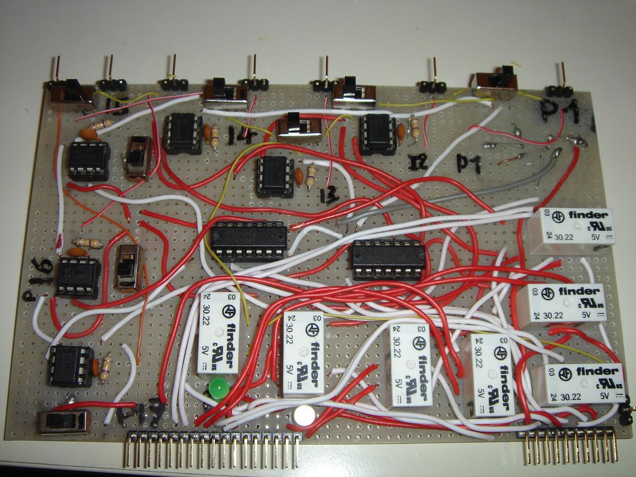
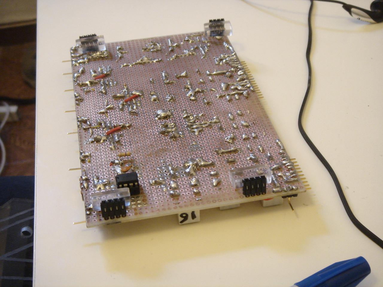
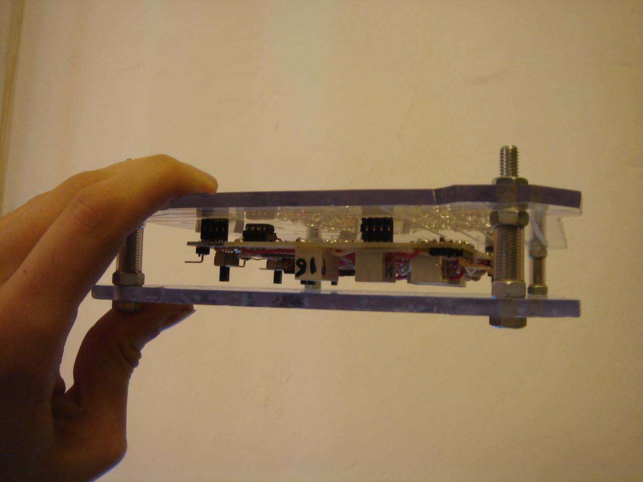
And this is the completed circuit!
Then I have done a quick job: the supports that keep in place the circuit in the circuit encasing:
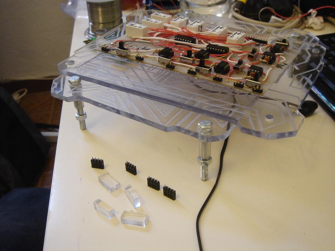
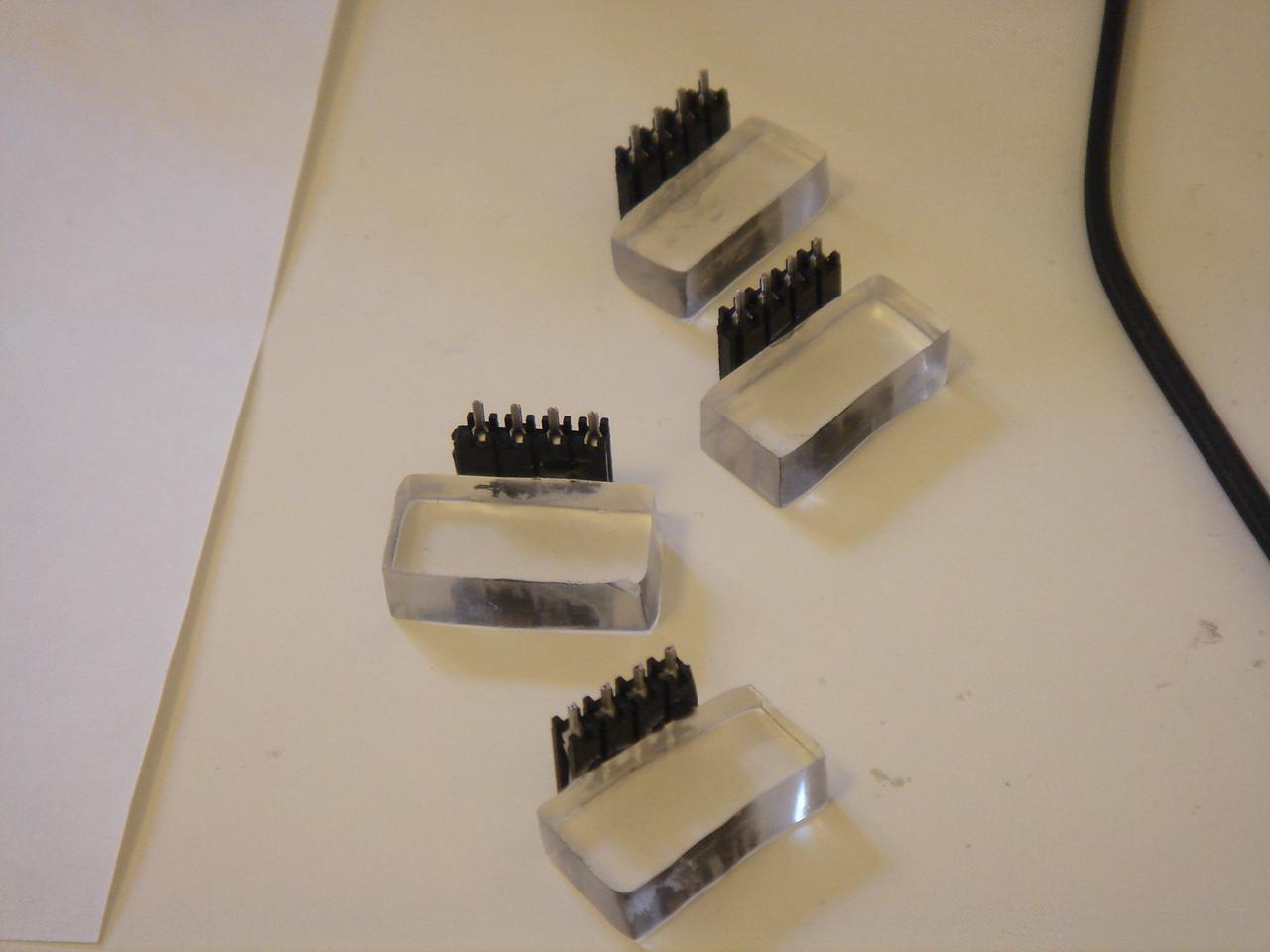
These supports are glued on the base of the encasing:
Now I must proceed with a support for the feedback LEDs, and a cable that connects the circuit with all the devices in the case.
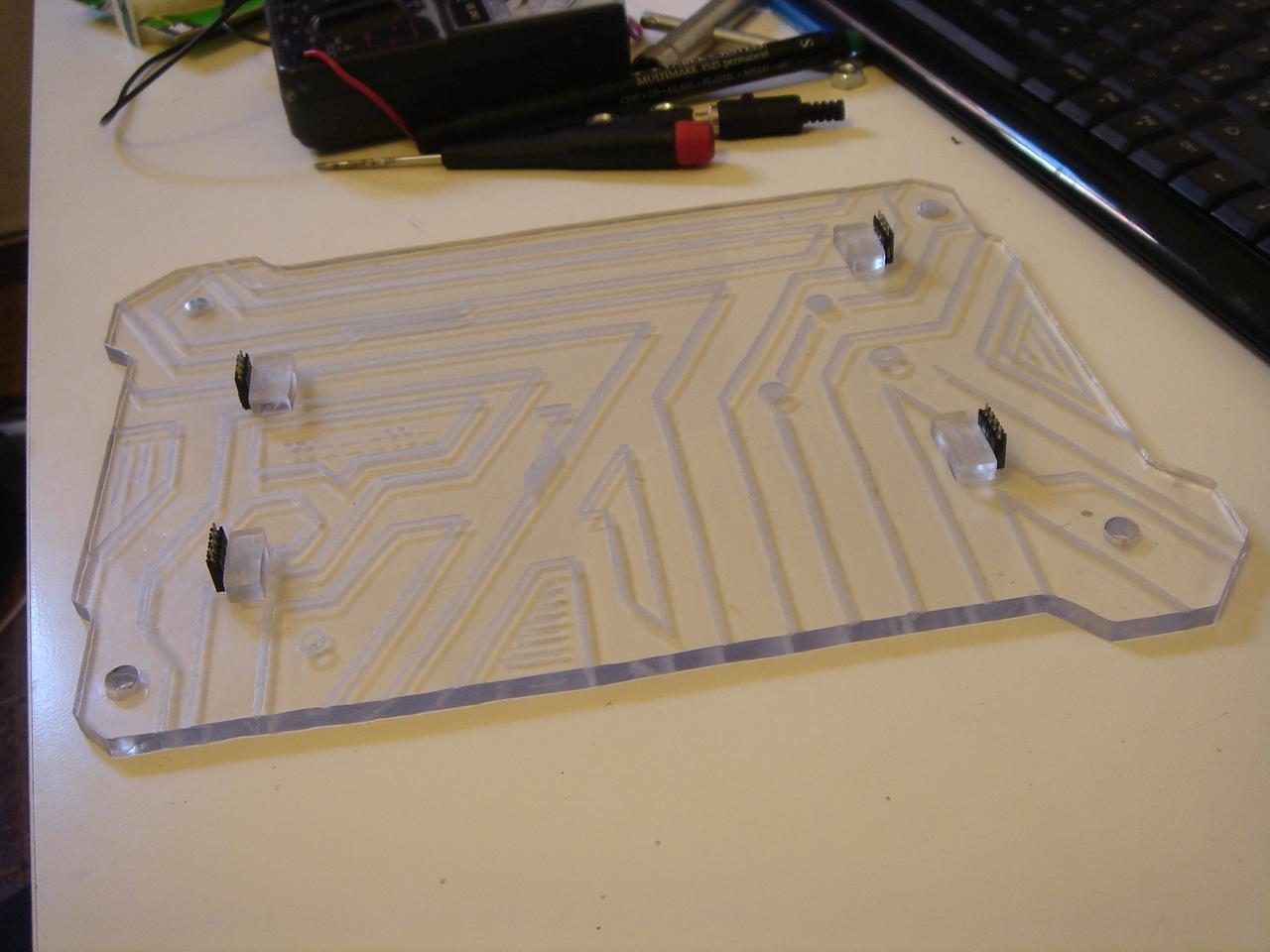
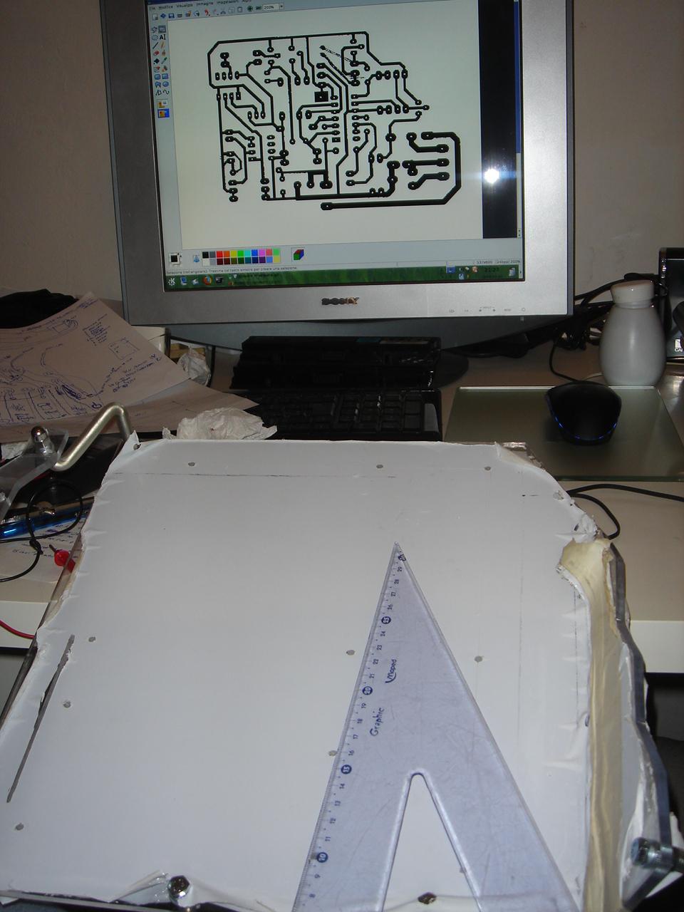
drawing the motherboard engraving
Here I’m drawing the engraving for the motherboard structure, in “printed circuit” style:
I downloaded some printed circuit images, and then I started to draw one on the mobo support, trying to keep the style of the real ones:
Unrelated: I have draw the actual circuit diagram of the touch sensor circuit interface to the rest of the components:
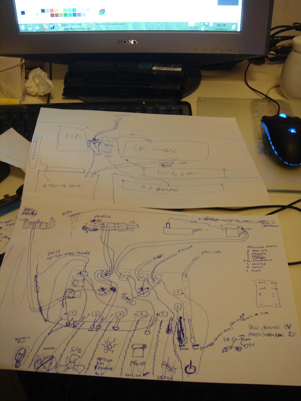
(I know, i know… this is a very elegant and clean diagram 😀 )
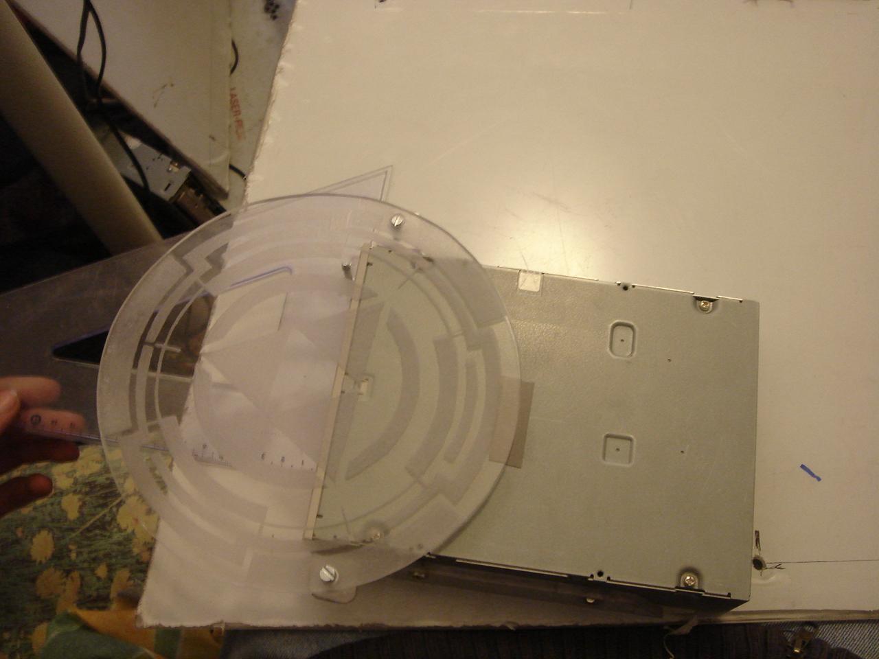
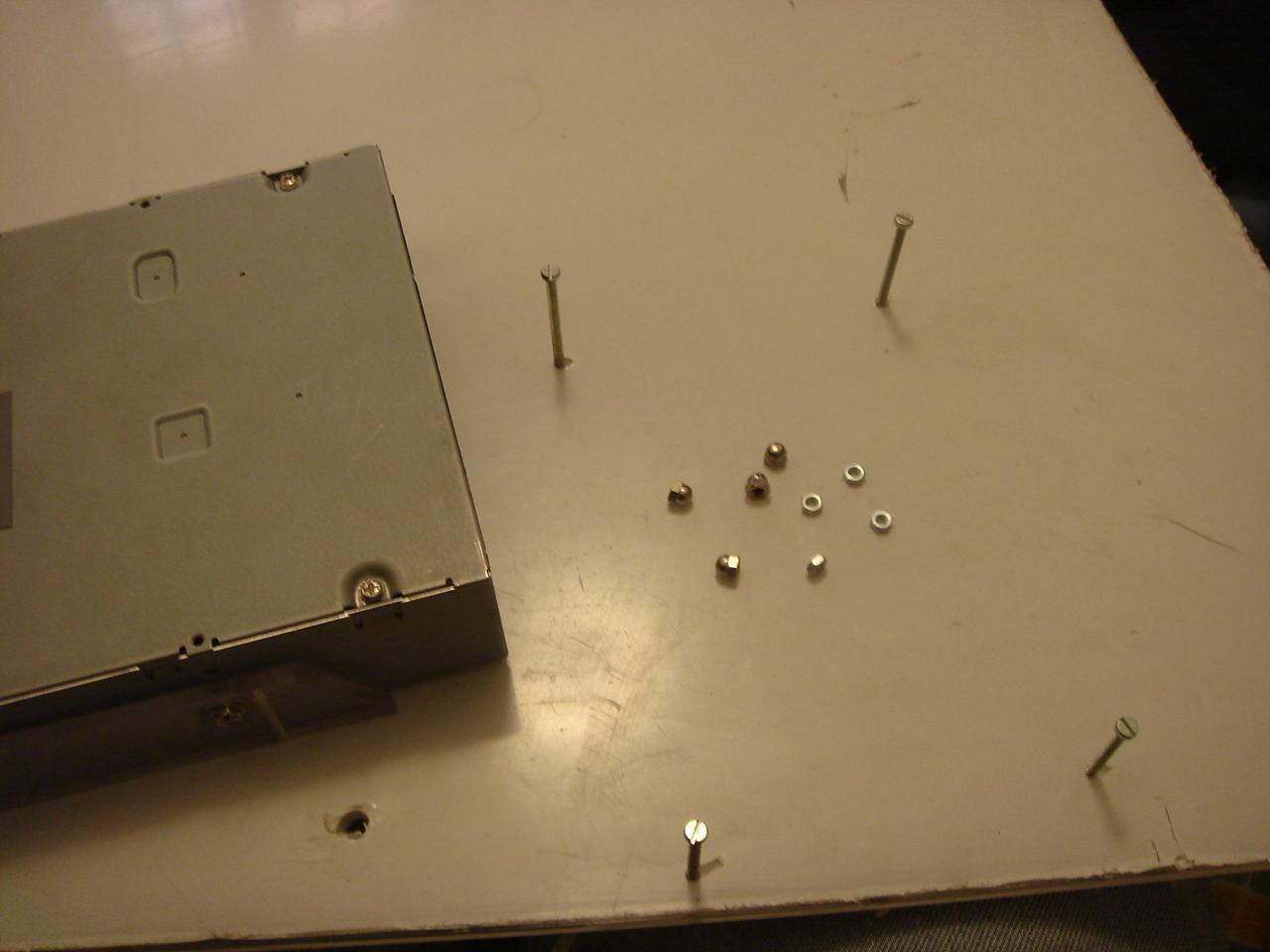
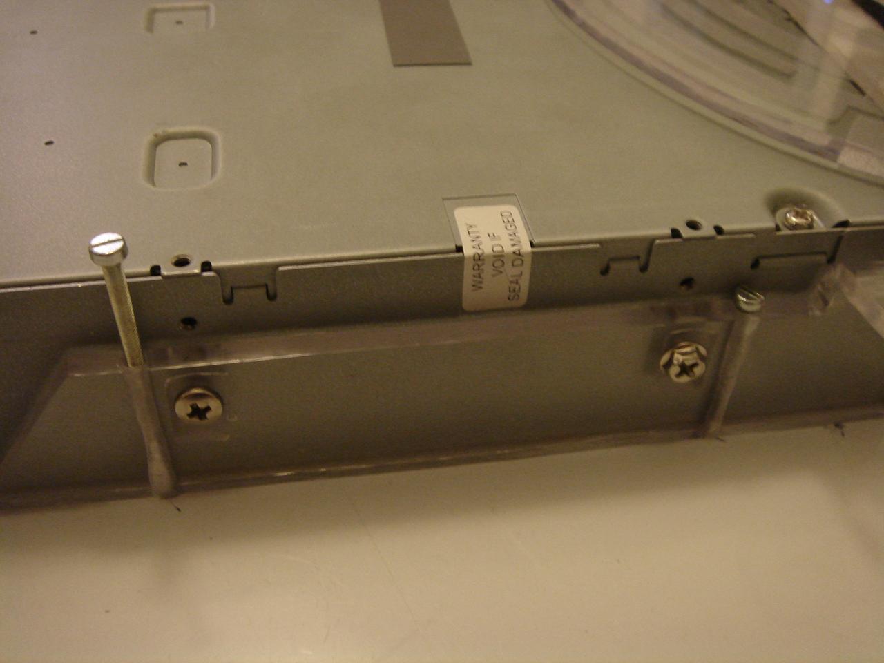
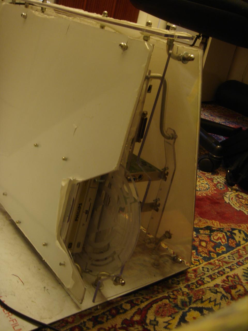
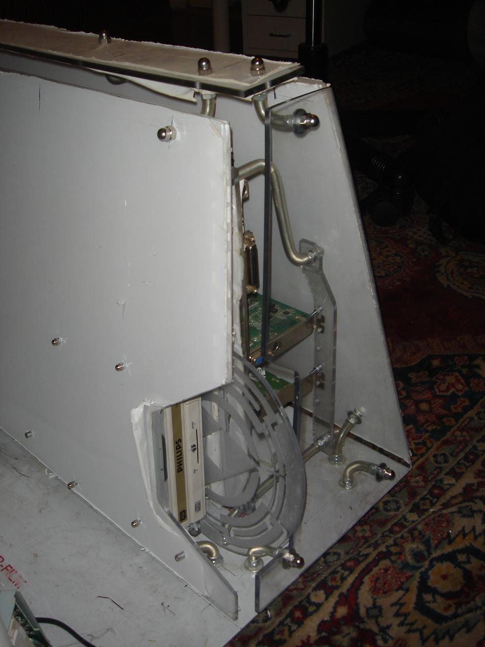
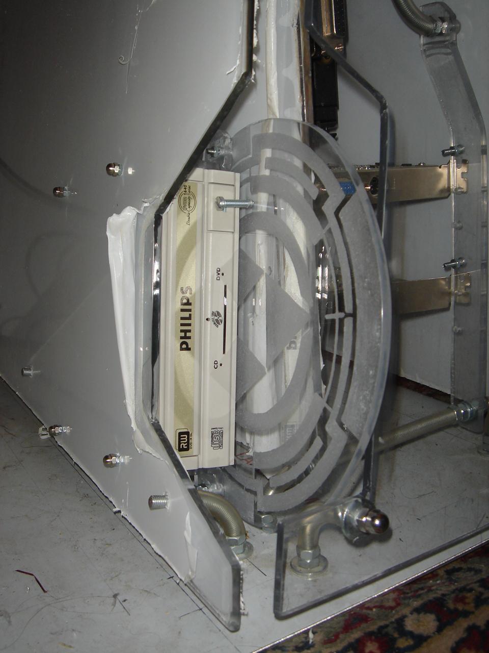
mounting the optical drive structure
I mounted the optical drive structure inside the case:
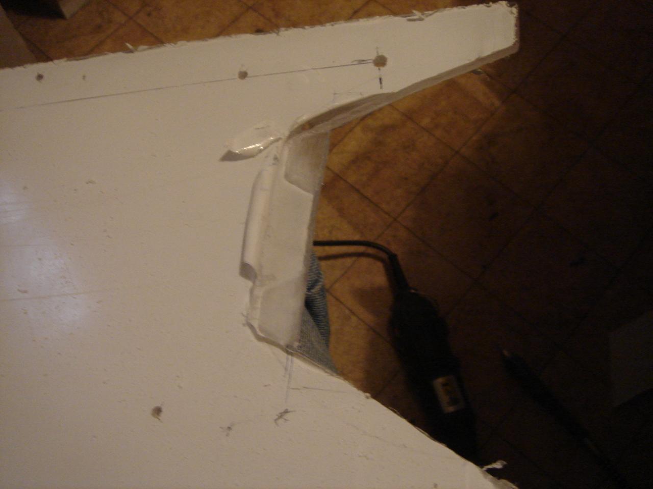
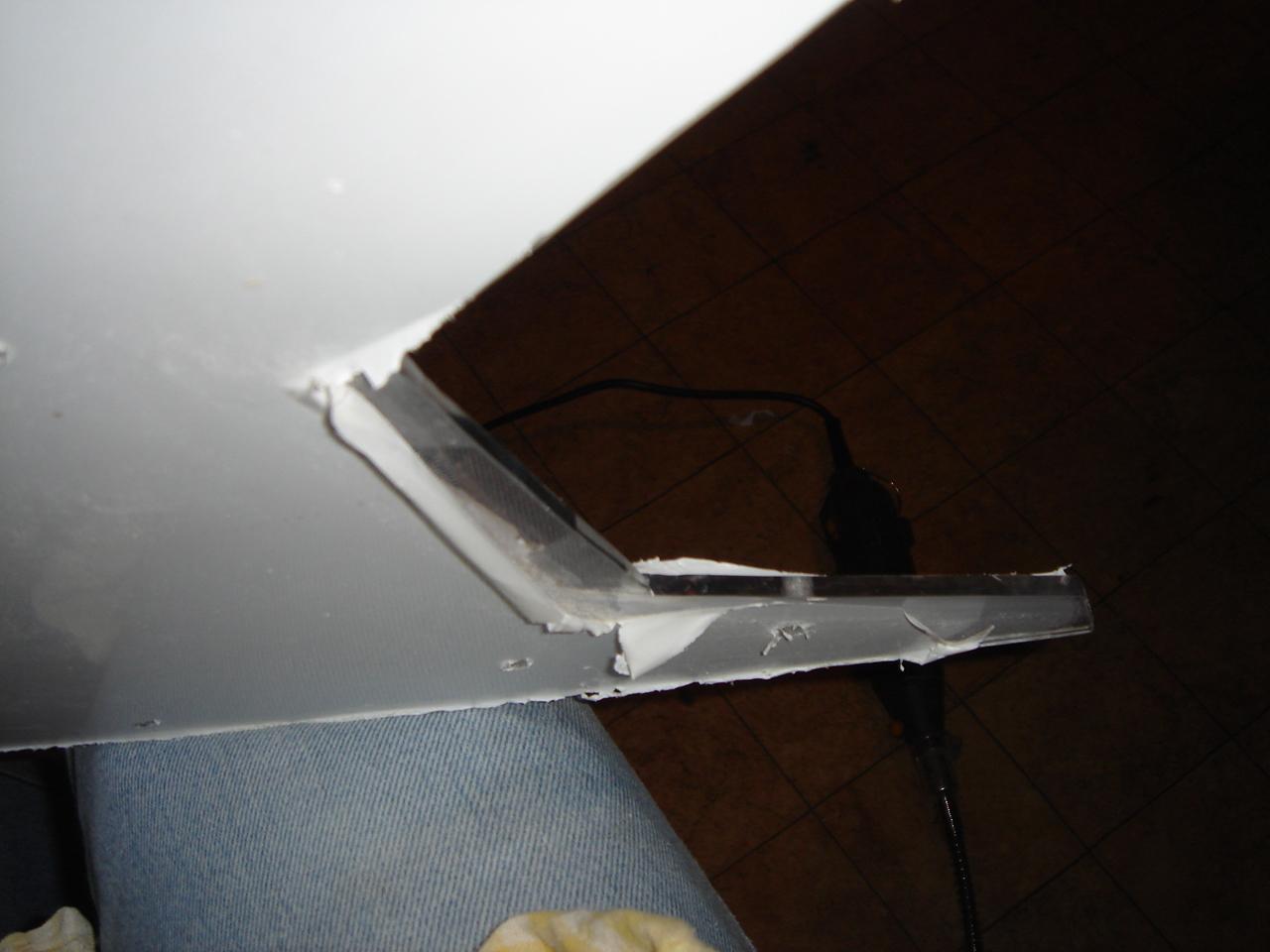
I cut (and polished the edges of the cut) of the small side wall:
the side of the case with the small side wall mounted:
At this point I also had to cut the big wall behind the screen:
The Tron disk in place seen from the outside:
The whole structure completed and assembled:
engraving the Tron disc (optical drive structure)
Now it’s the turn of the engraving… what kind of Tron case would be without a Tron disk?? 😀
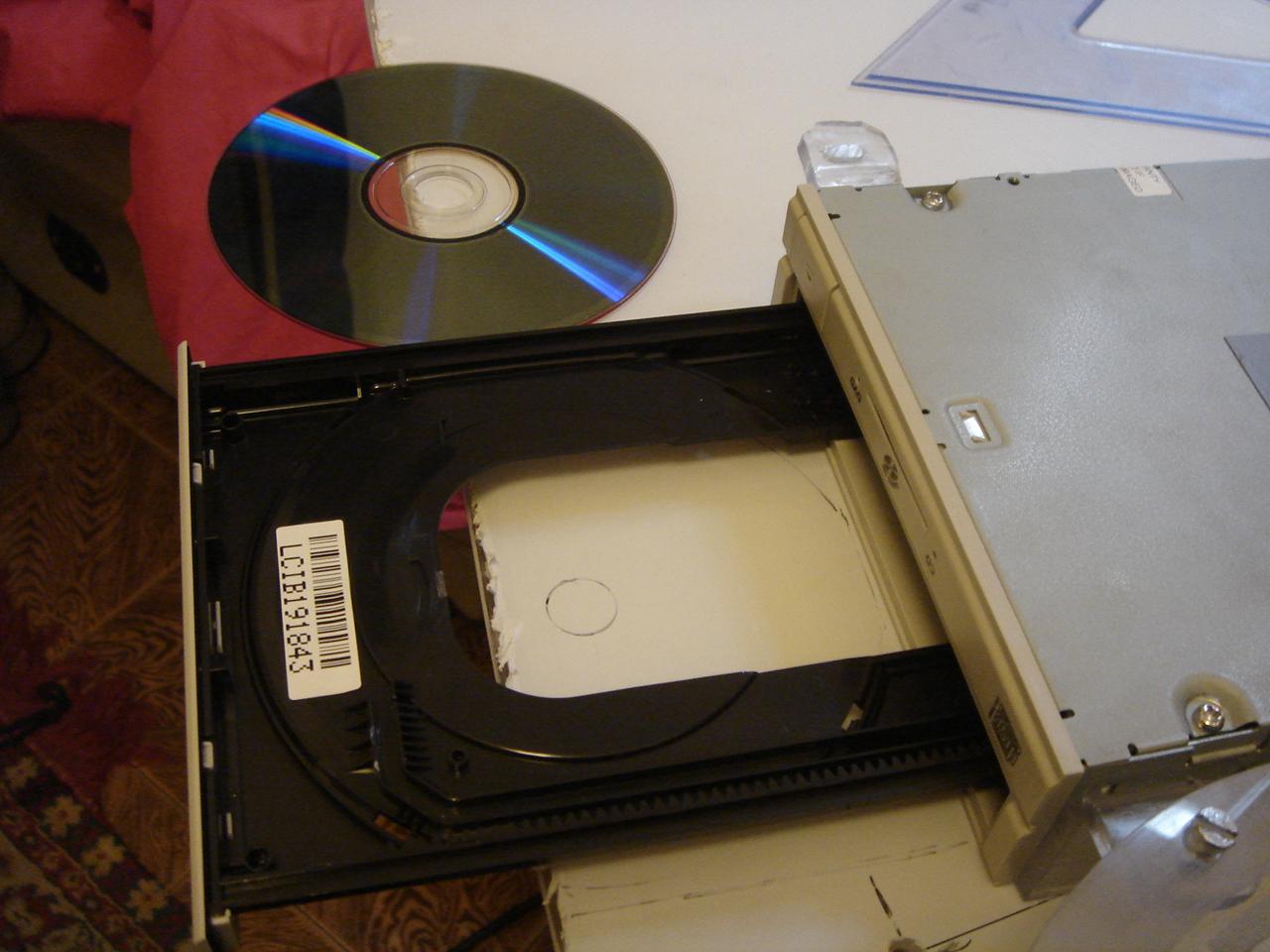
I have taken out my beloved game dvd, to use it as a reference for the disk:
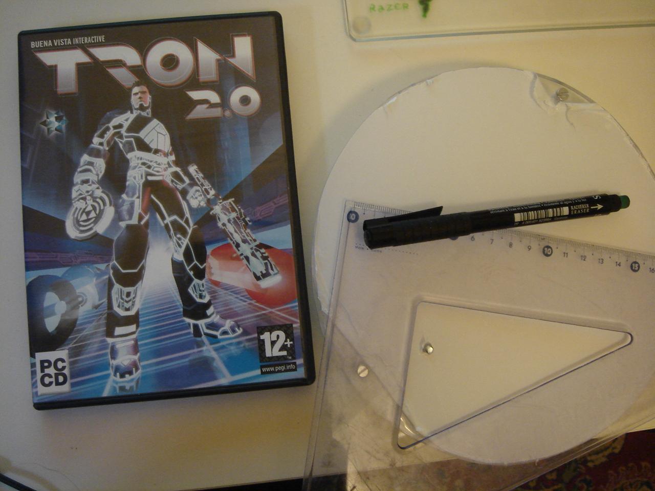
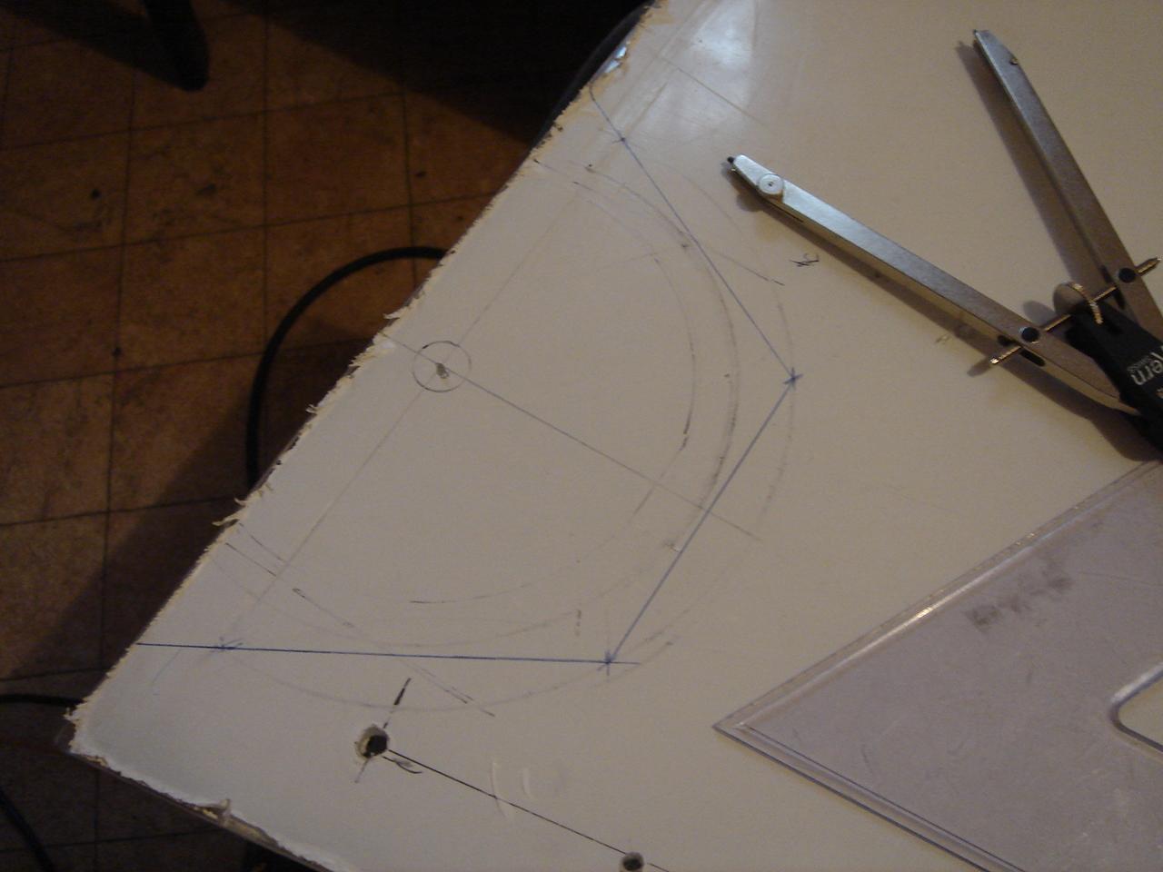
and I started to draw it:
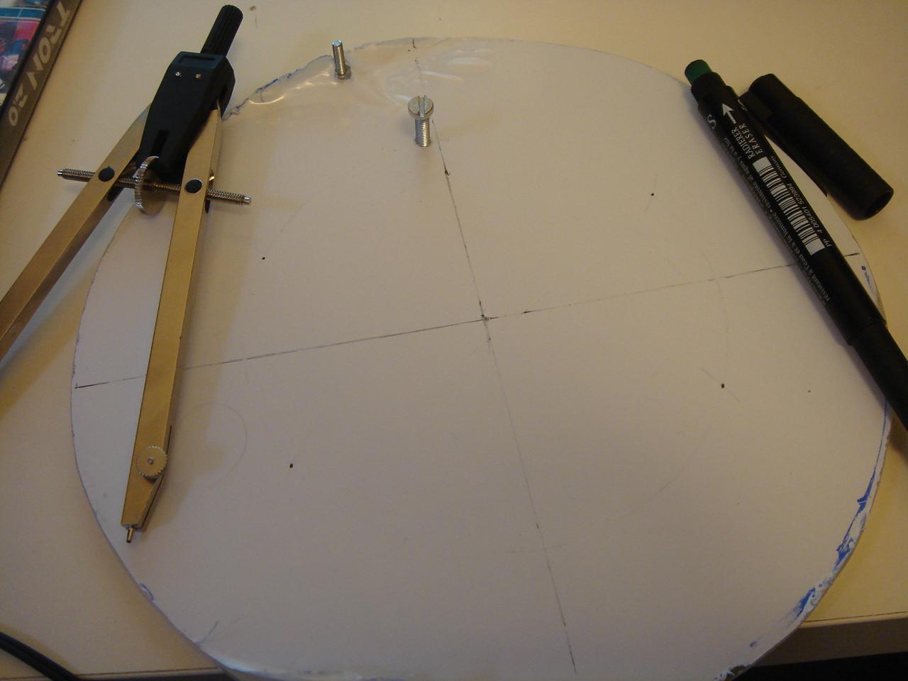
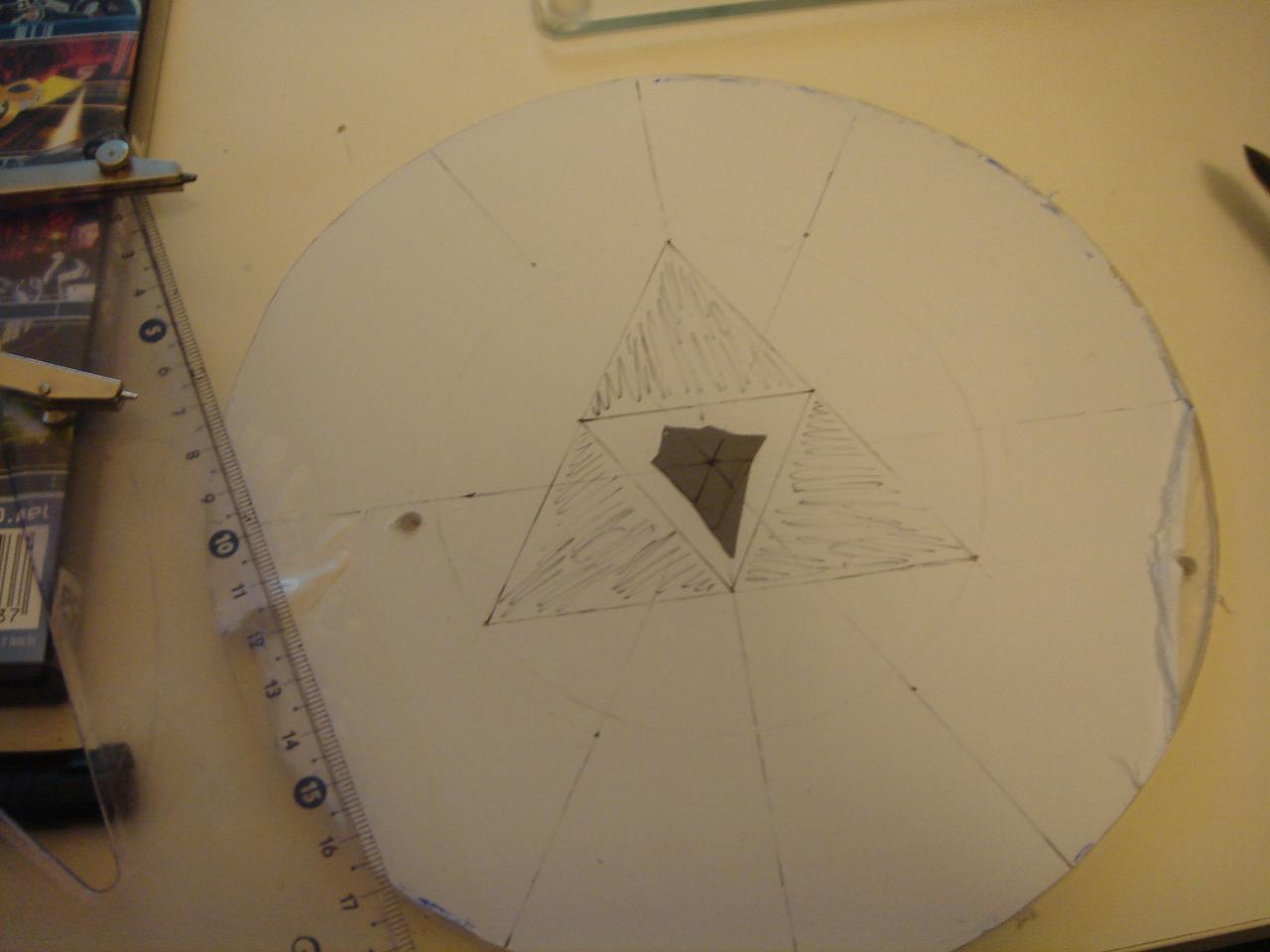
the completed drawing:
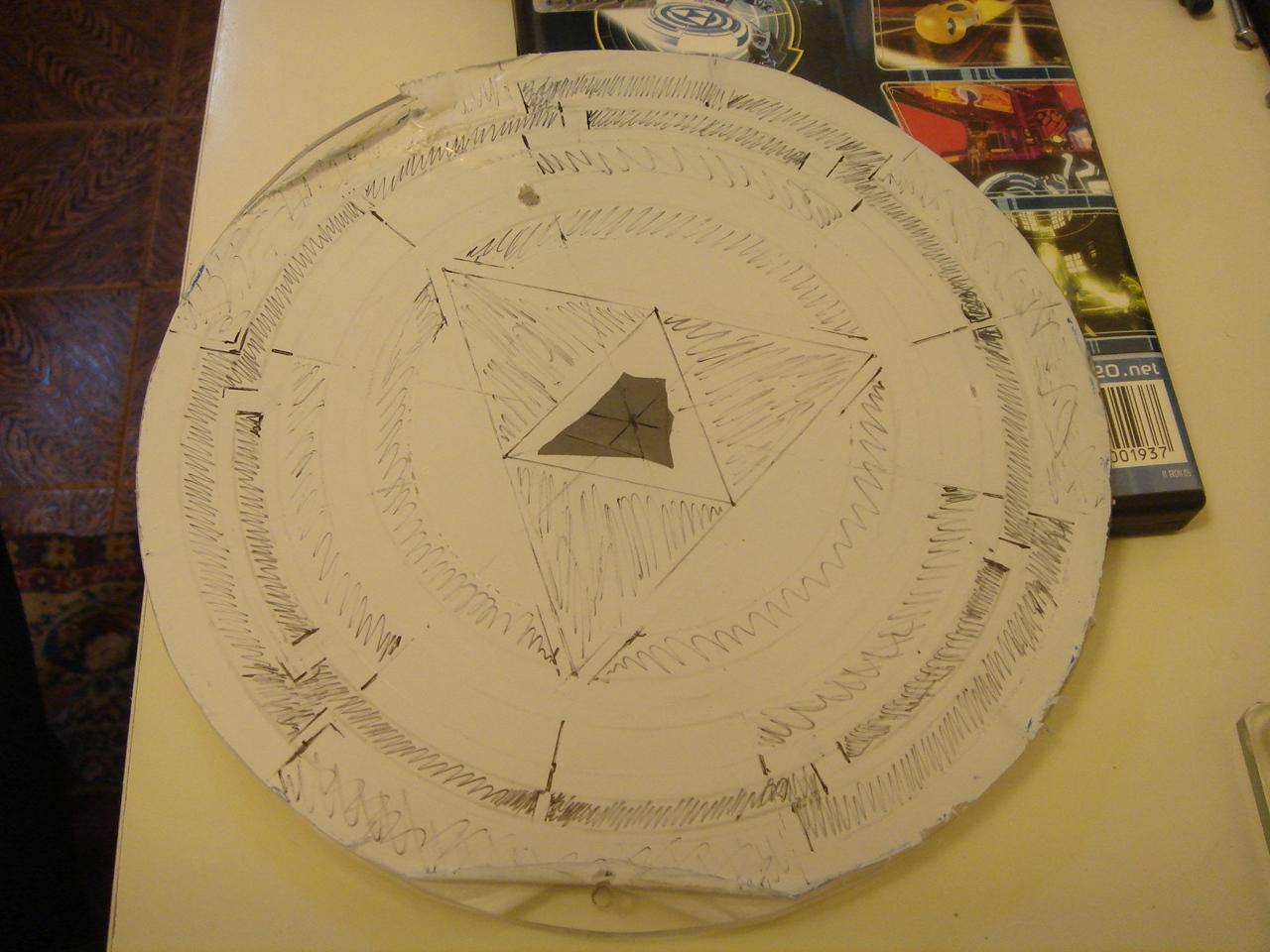
then I started to engrave it:
then I removed the white film, to proceed with the second pass:
And the finished result, after the second pass of engraving 😀 :