In this video we can see the mechanism for the opening of the optical drive tray in action:
Monthly Archives: July 2018
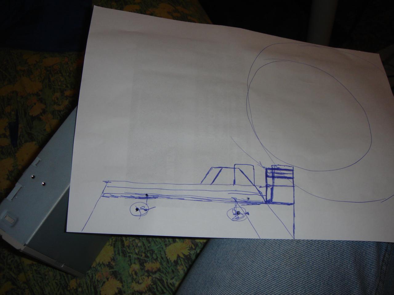
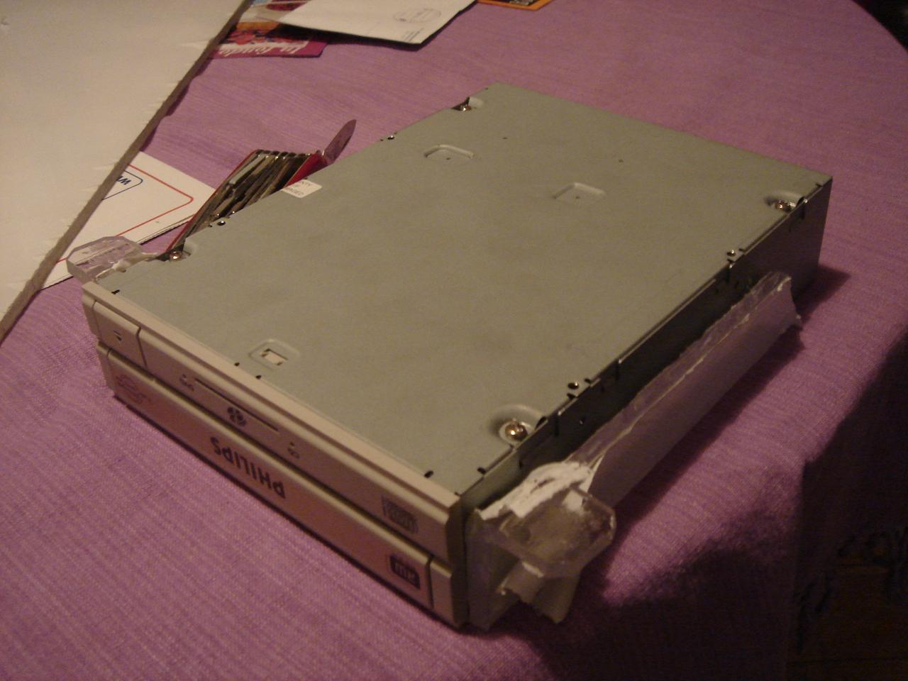
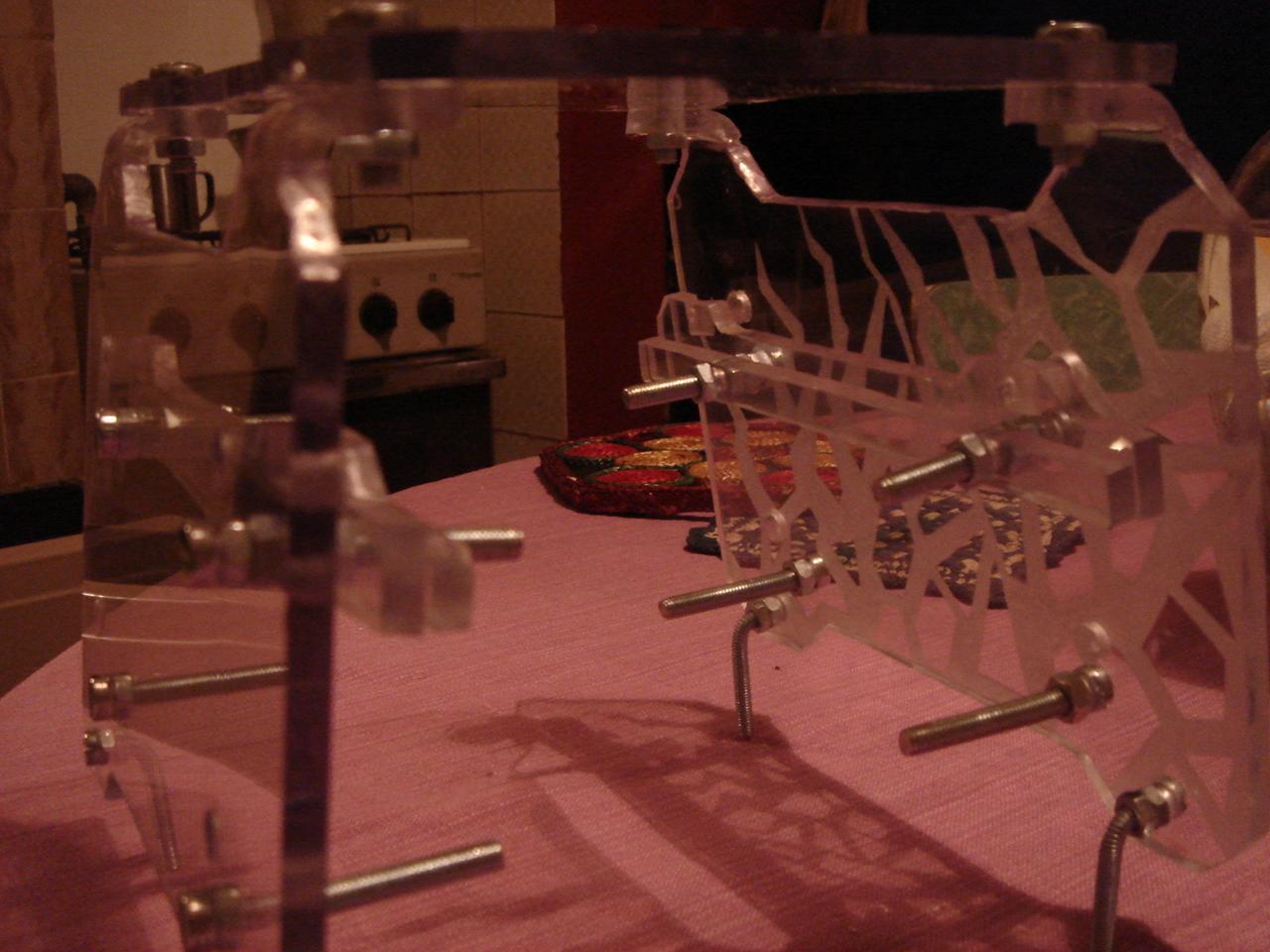
optical drive structure
The structure of the optical drive is quite different from the others, because instead of the base will be mounted on a wall, more precisely on the wall behind the monitor, with the tray opening to the right.
The problem is: how to make a cool way to open the drive tray?
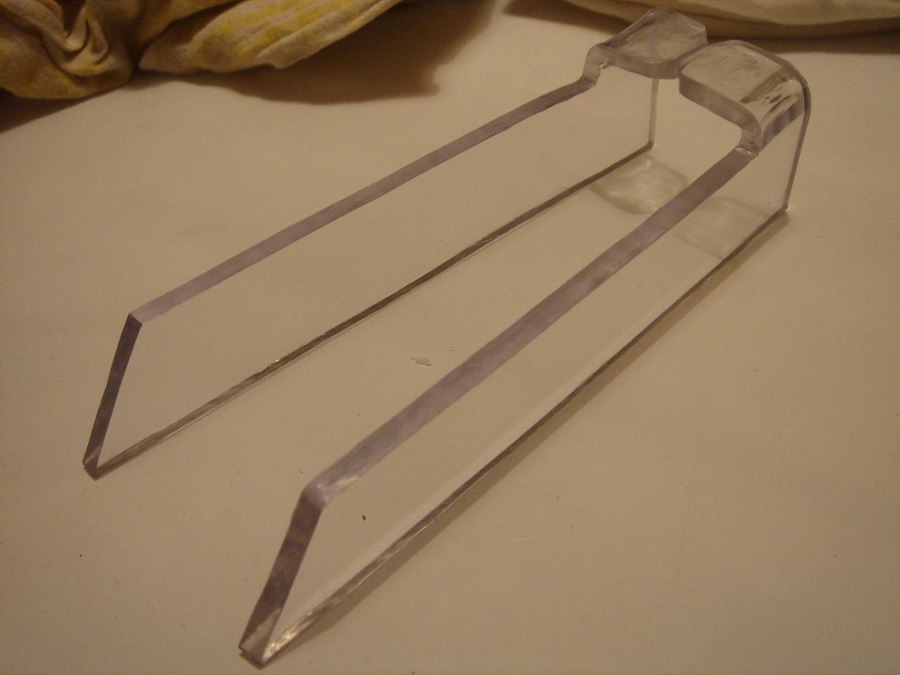
This is my idea to do it 😀 :
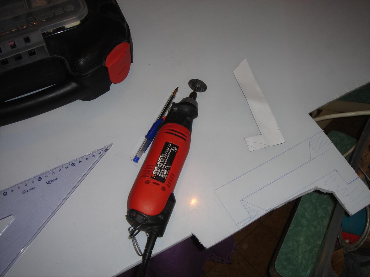
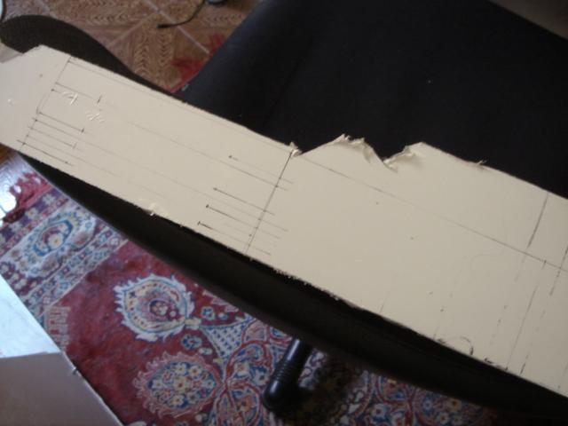
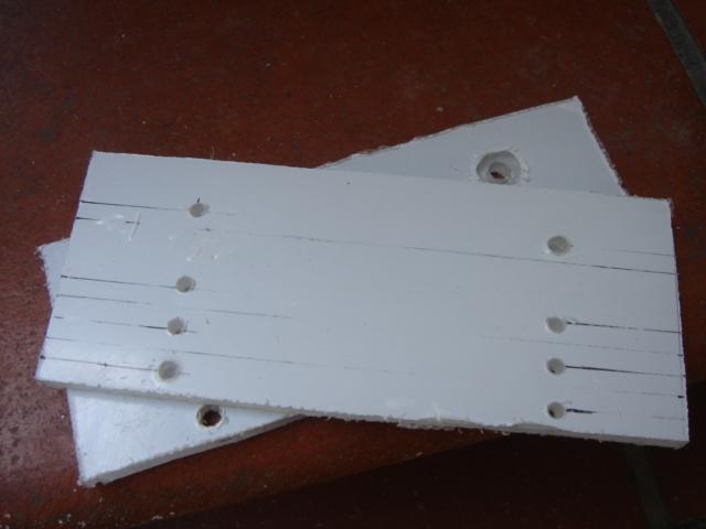
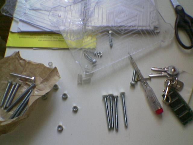
Drawing and cutting some pieces:
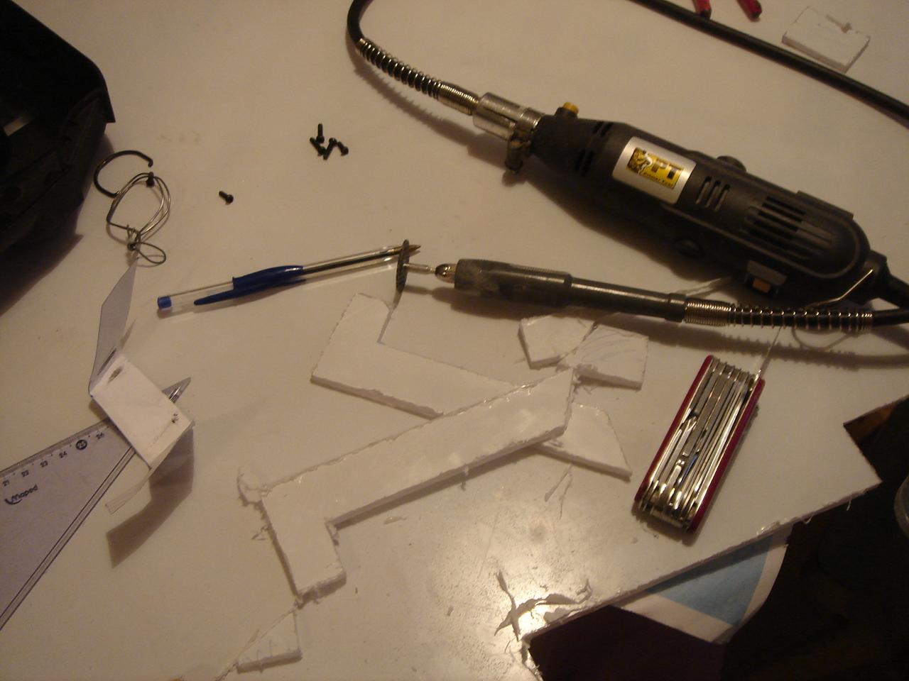
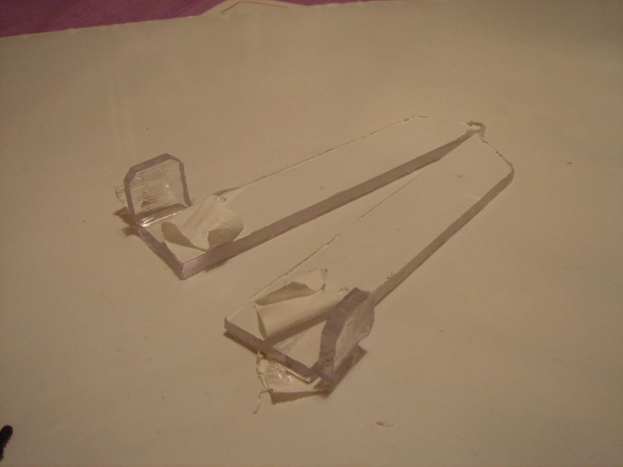
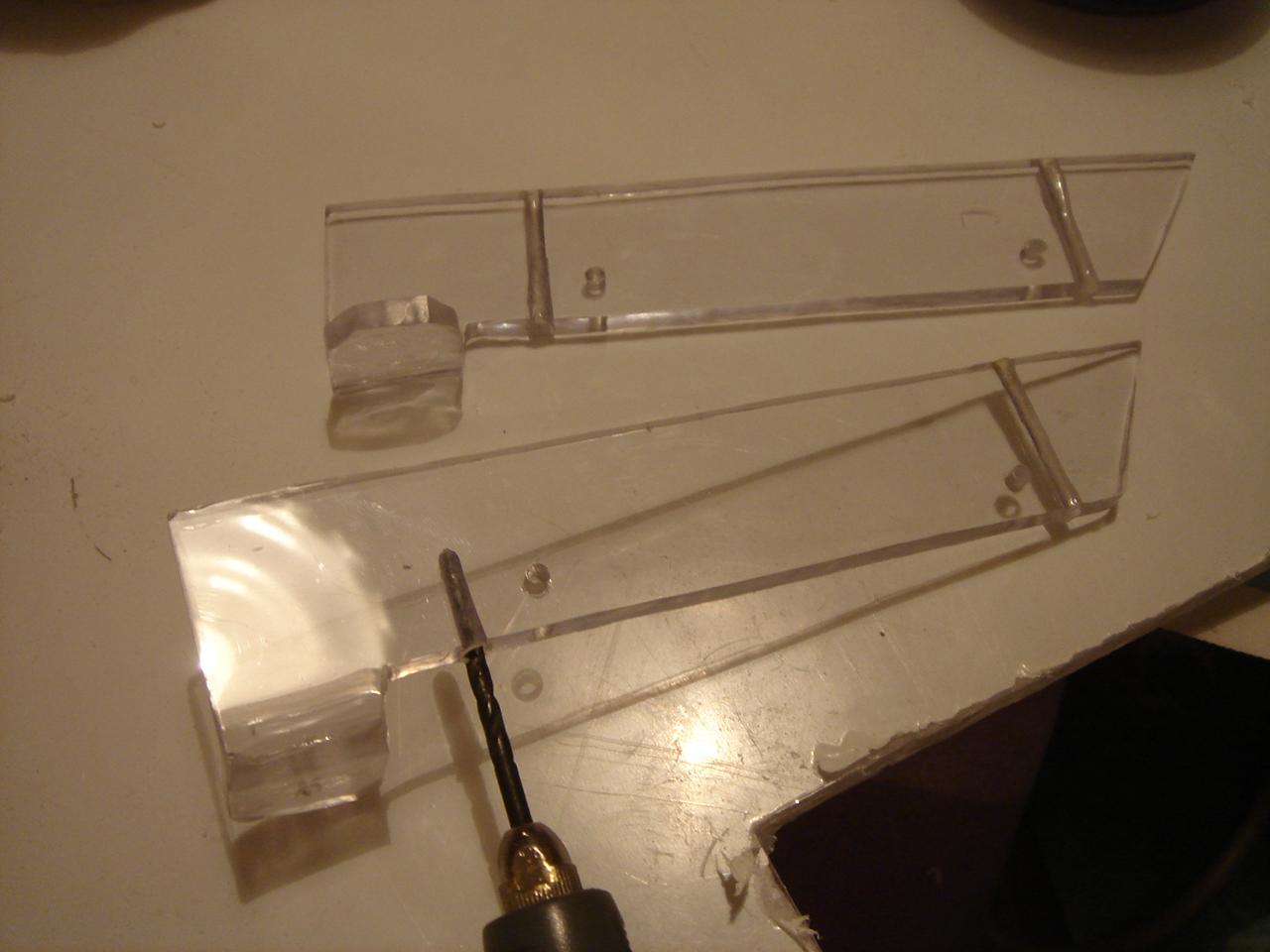
Then, as usual, I polished the edges:
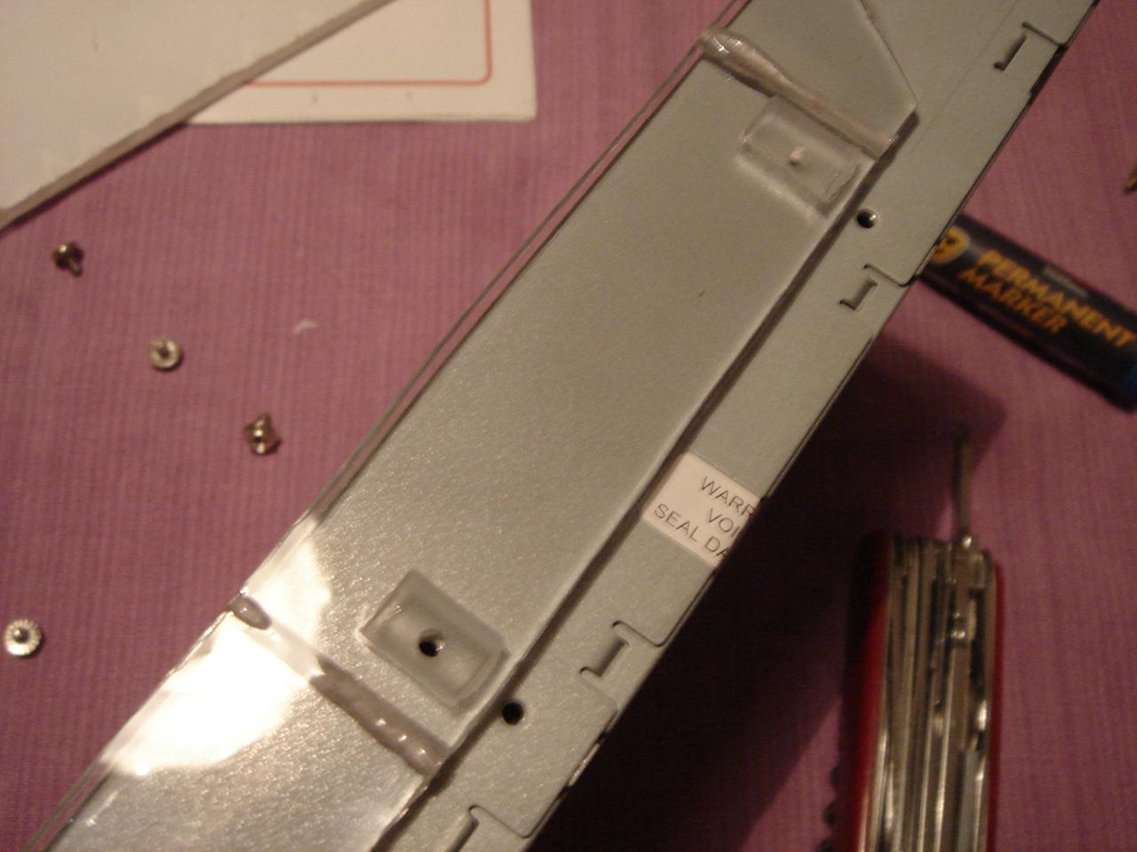
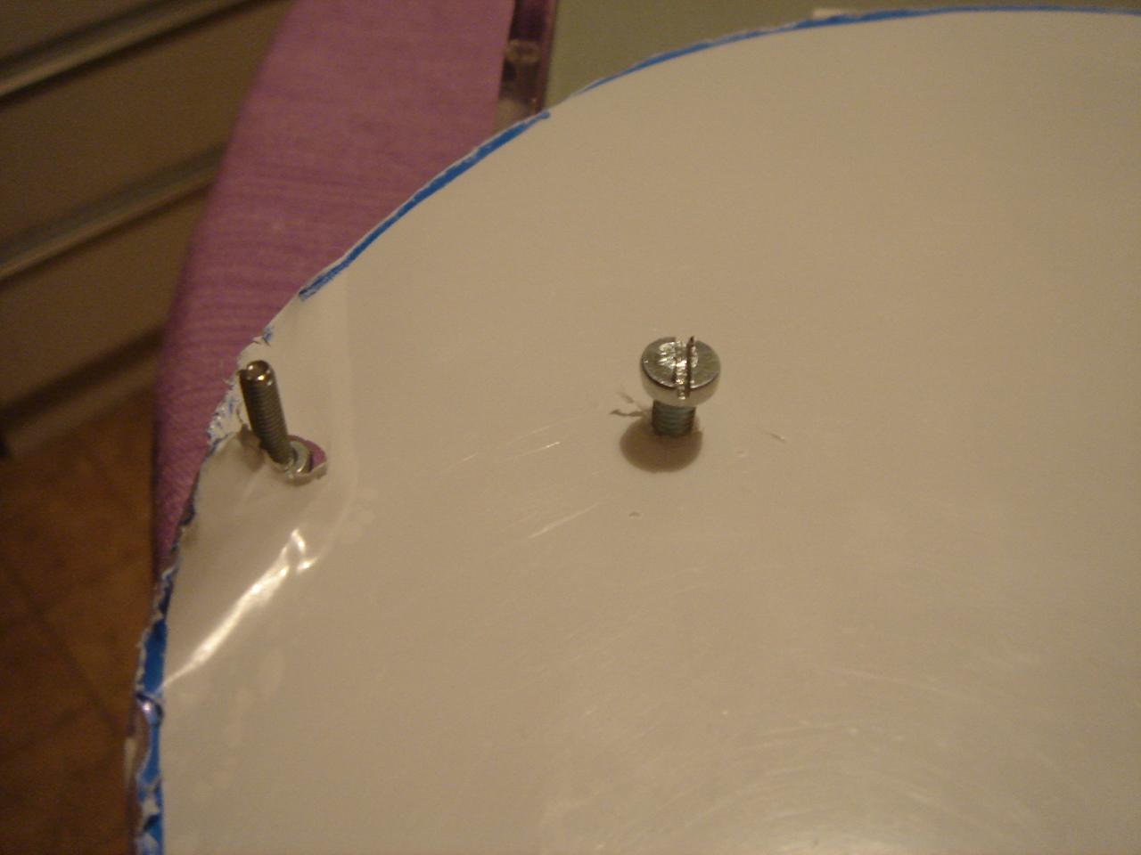
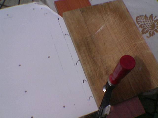
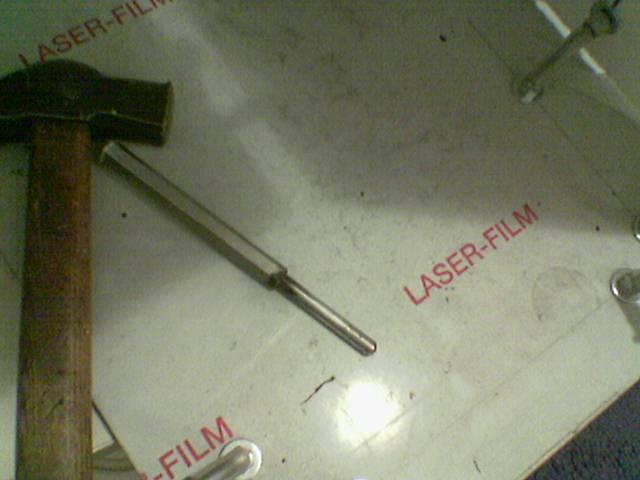
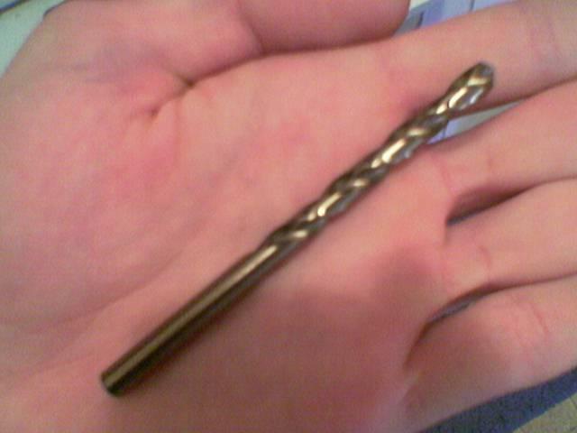
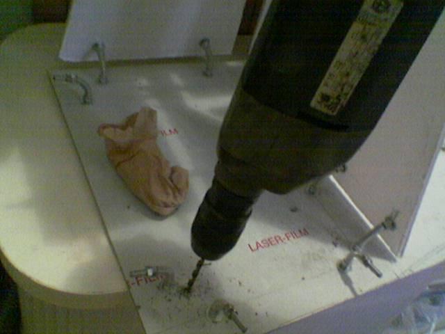
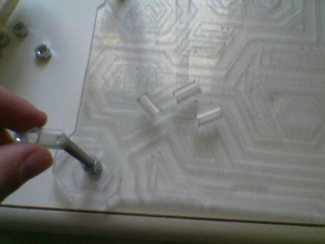
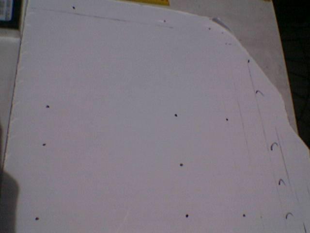
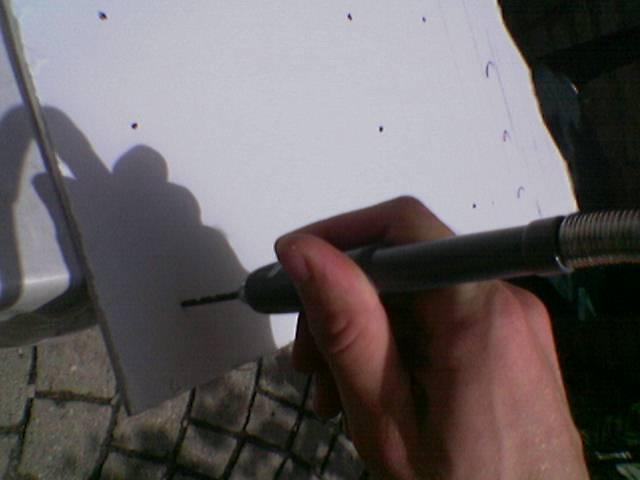
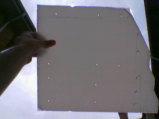
an I drilled the holes:
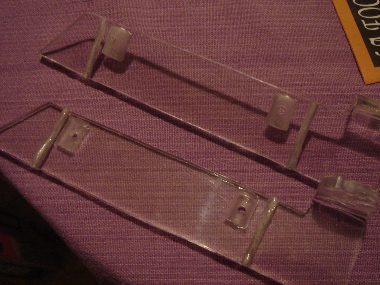
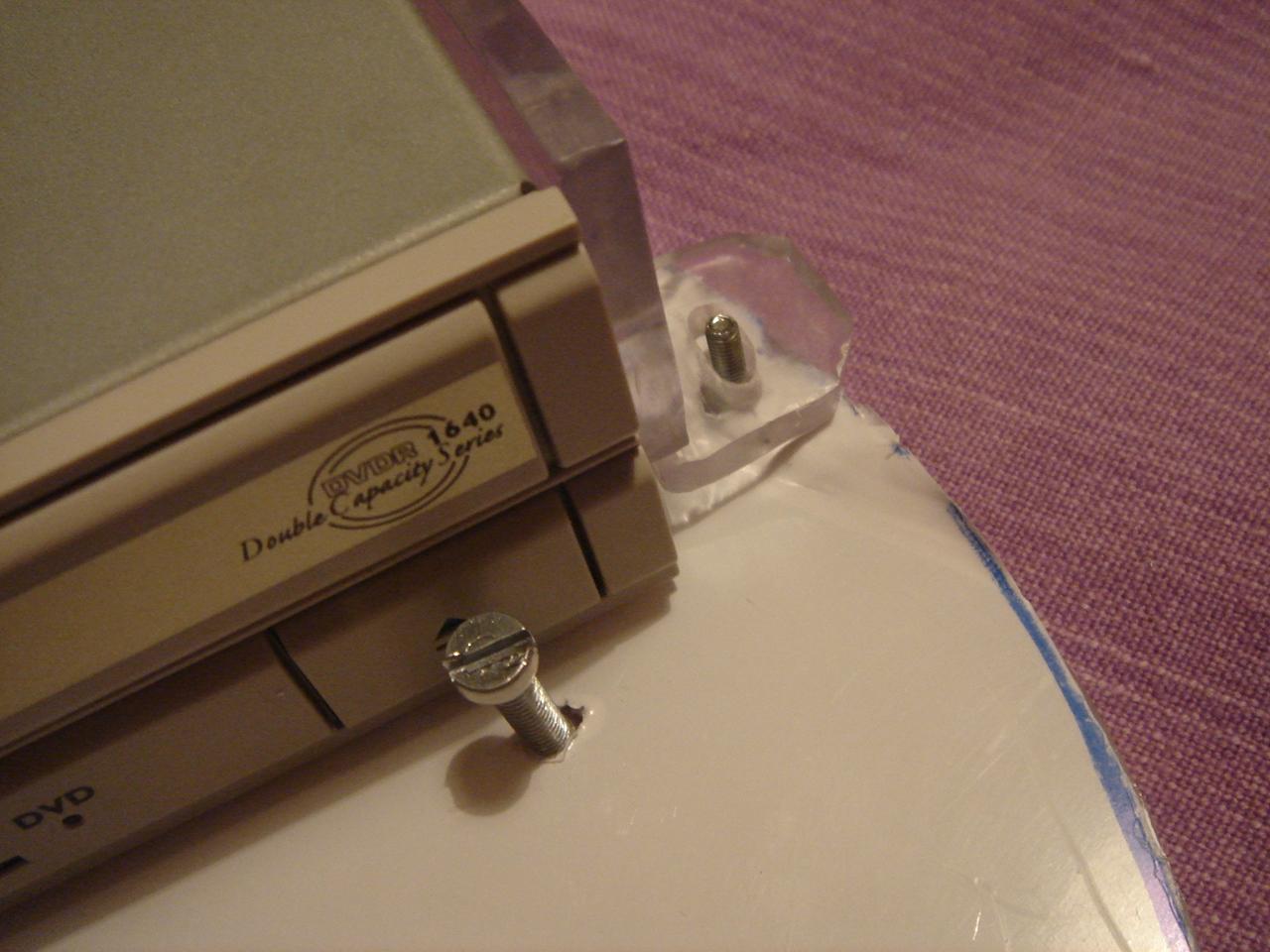
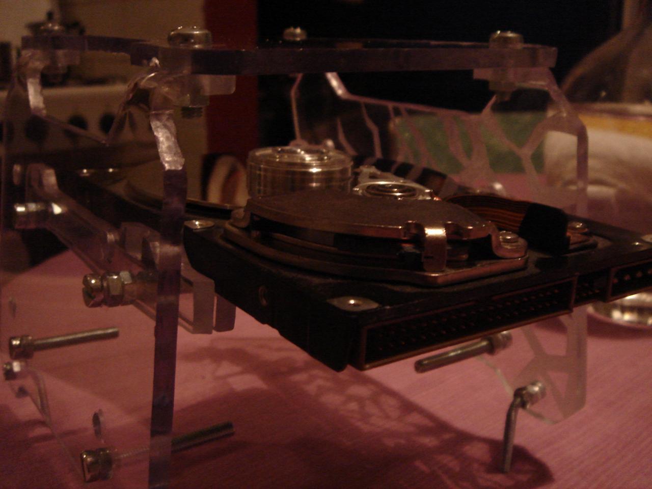
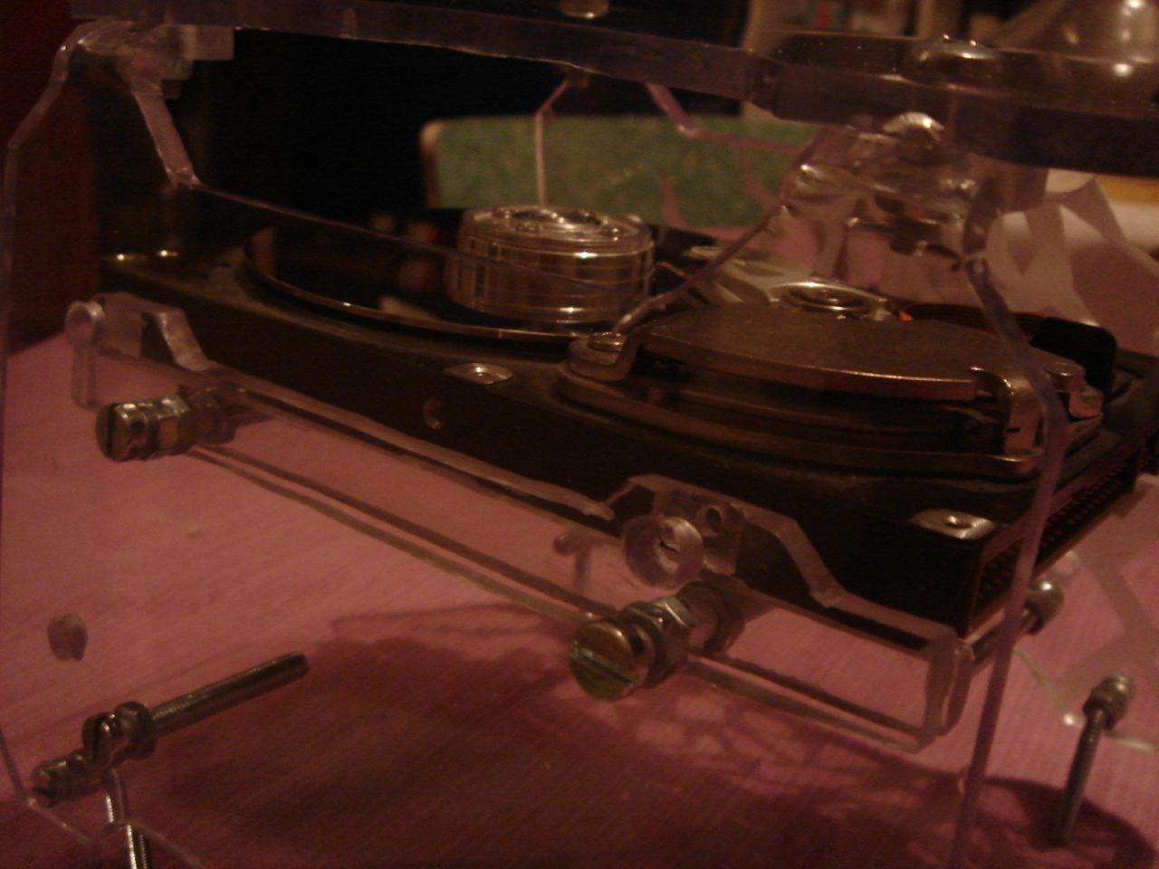
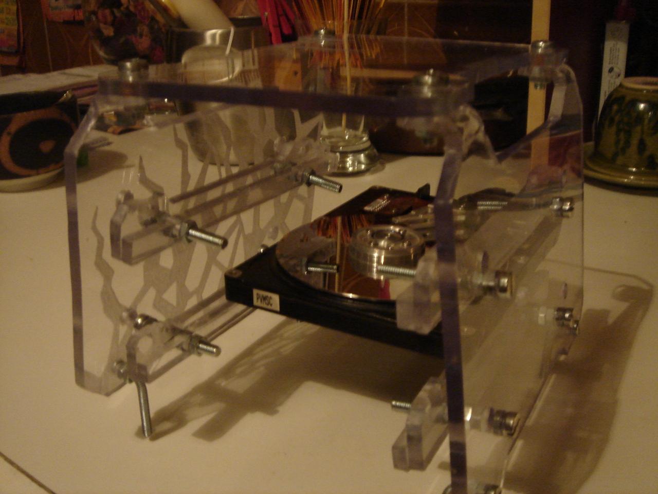
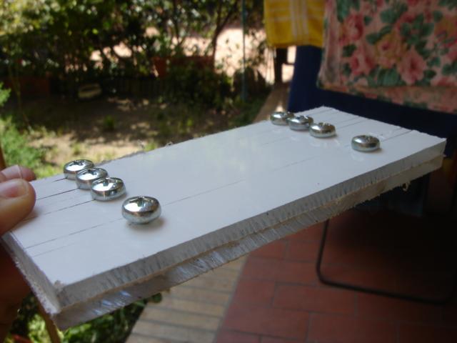
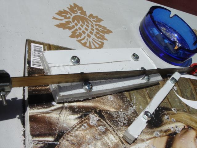
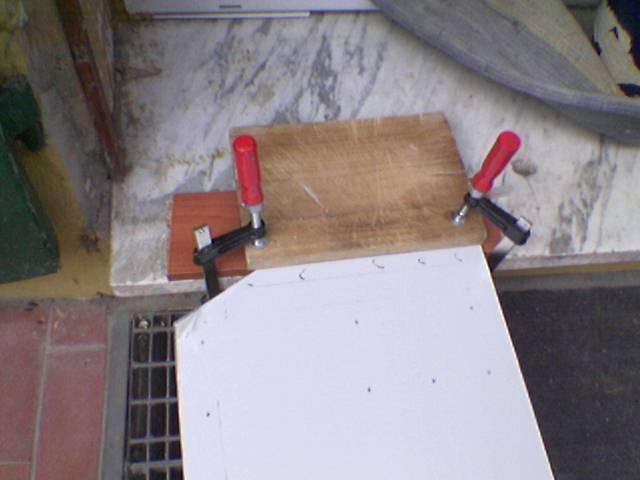
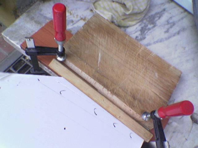
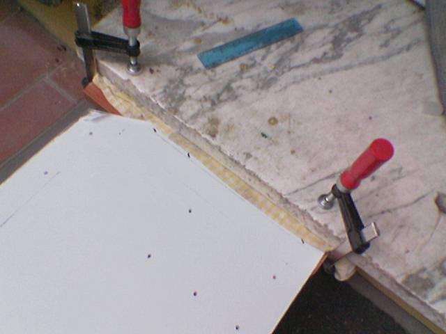
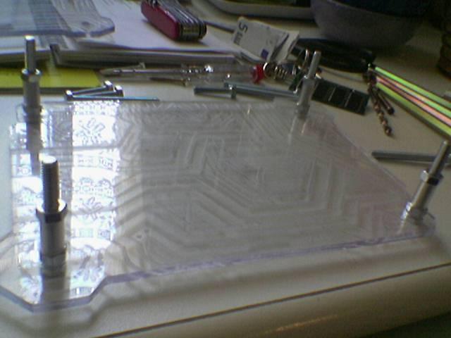
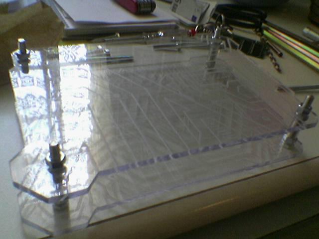
then I temporarily mounted the pieces on the optical drive:
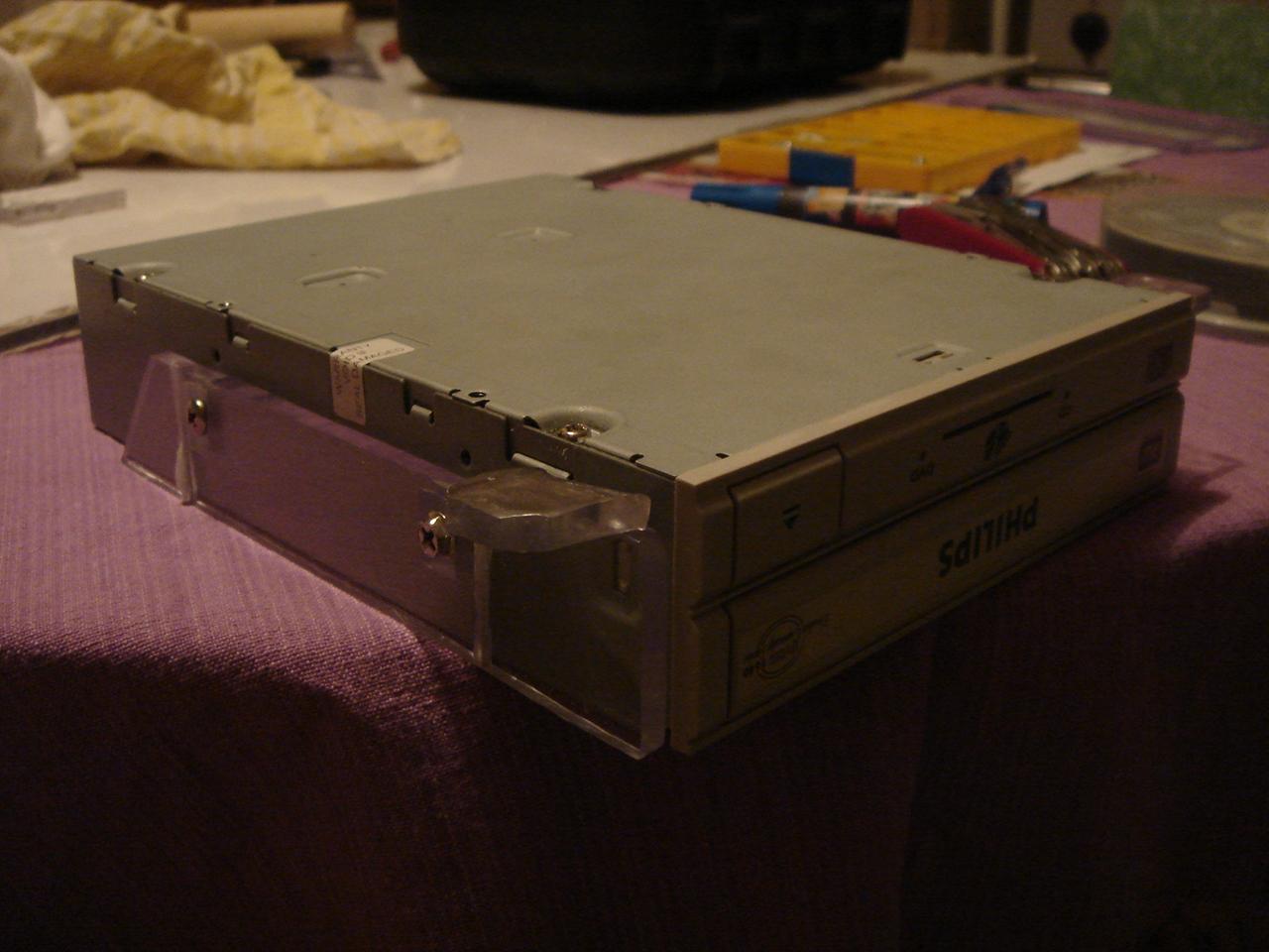
…in the last picture can you begin to guess something about the opening system that I had mentioned before? 😀
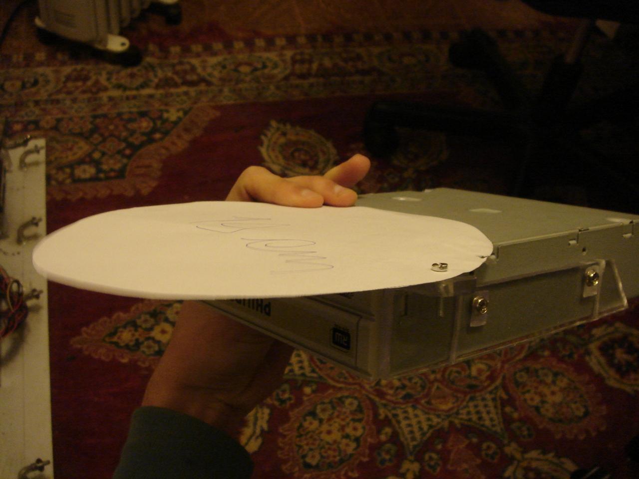
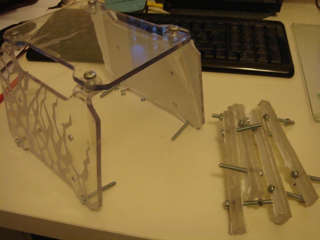
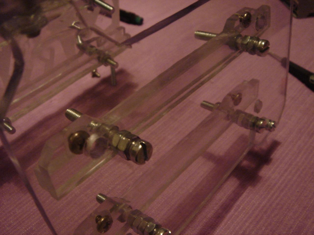
I finished the whole structure, I only have to mount it on the wall:
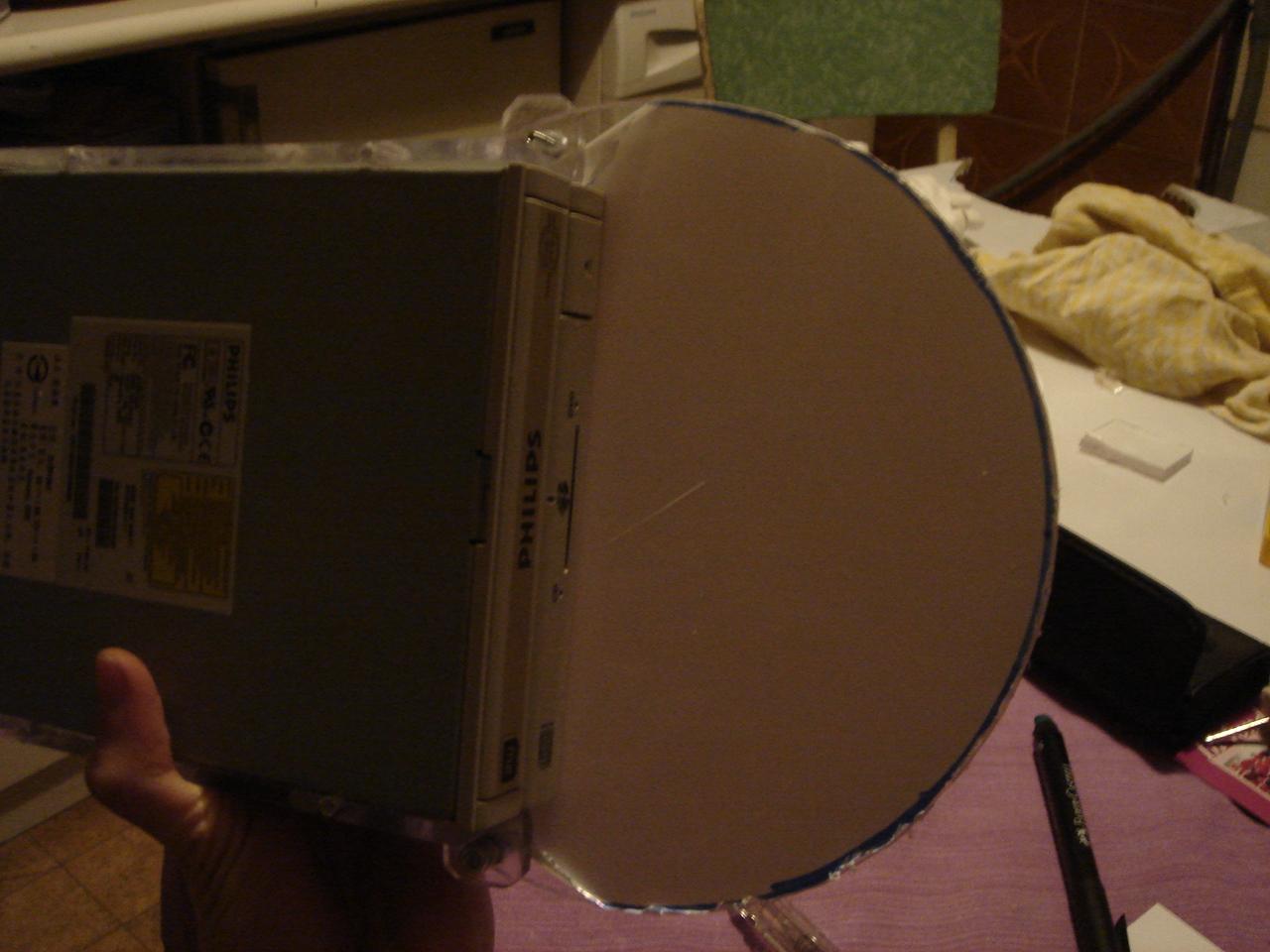
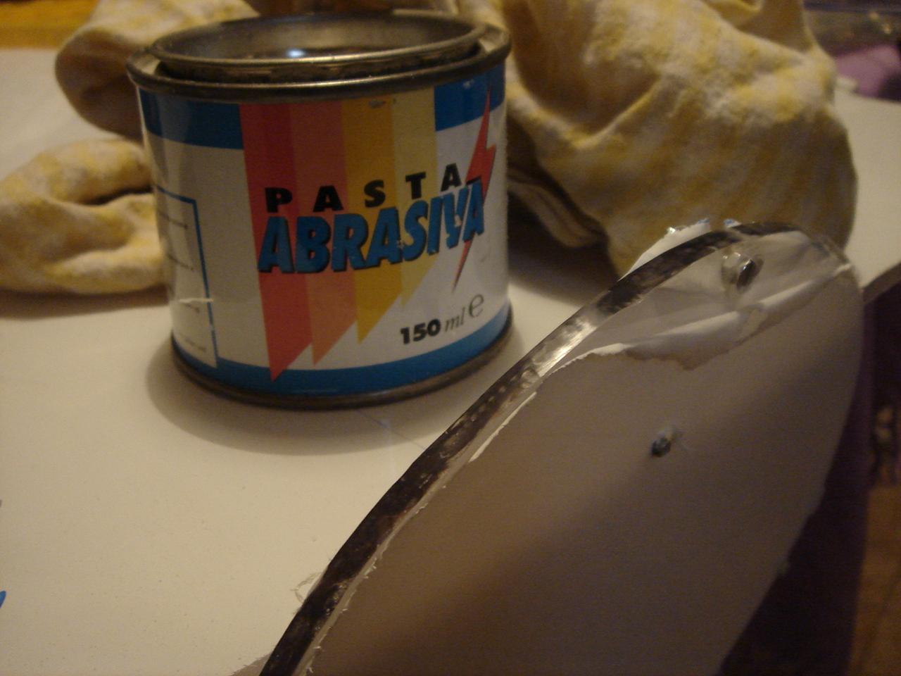
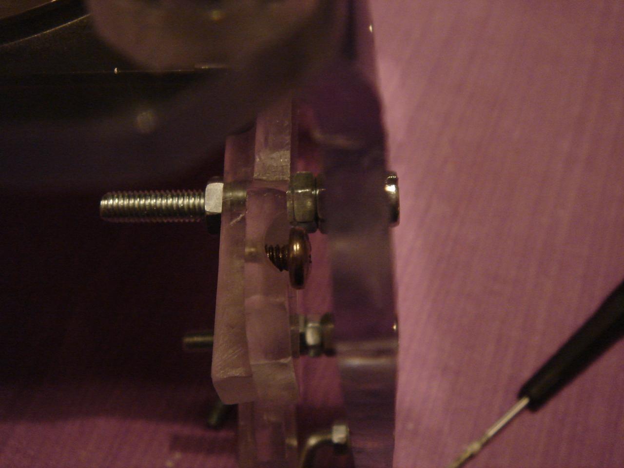
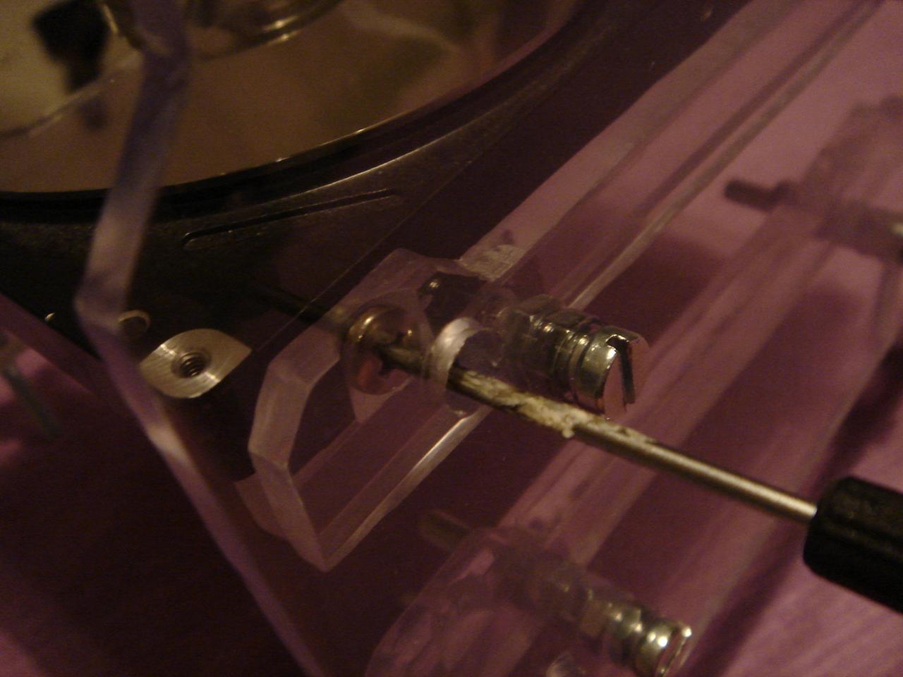
first, I needed a polycarbonate disk:
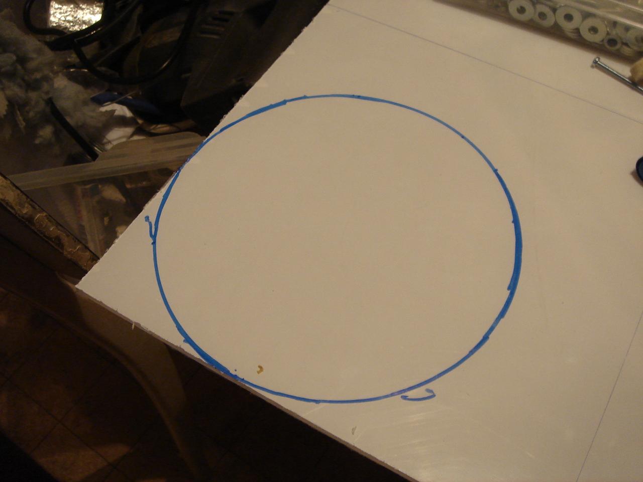
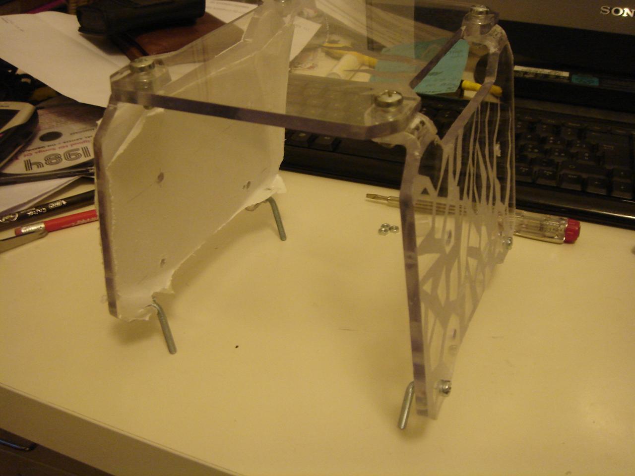
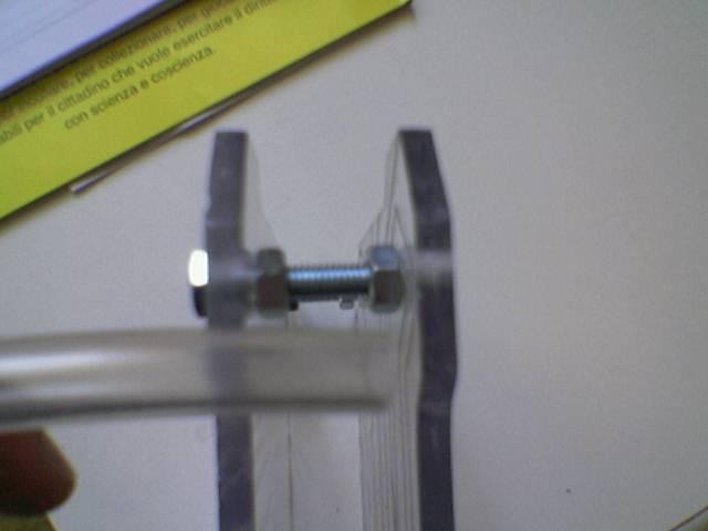
…this disk has to be mounted on the structure in this way:
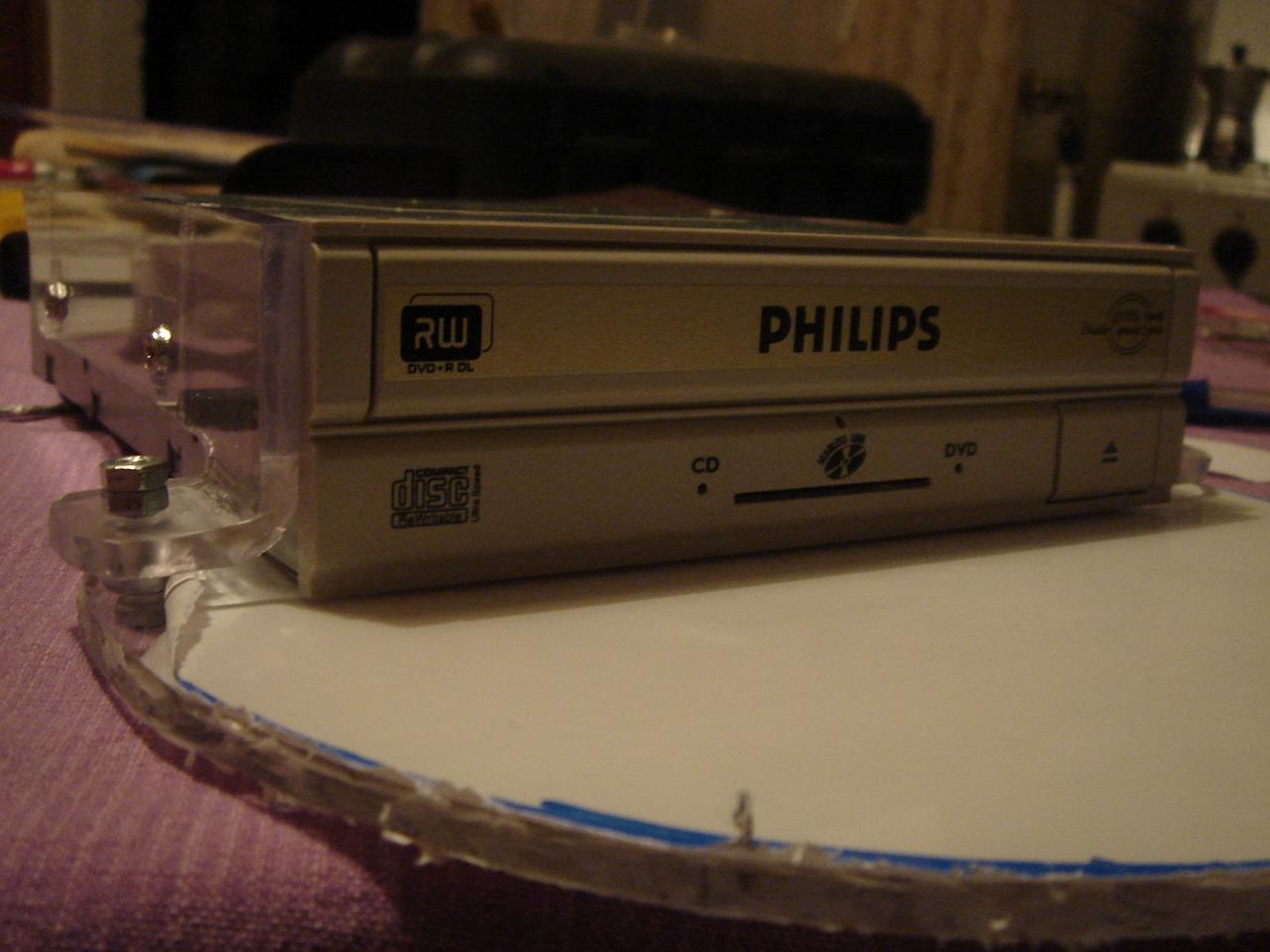
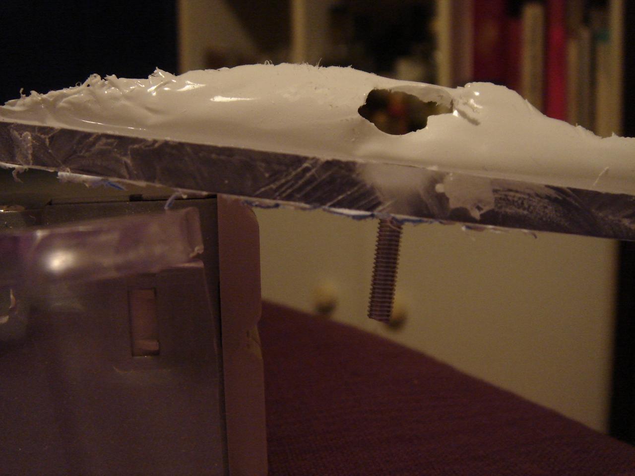
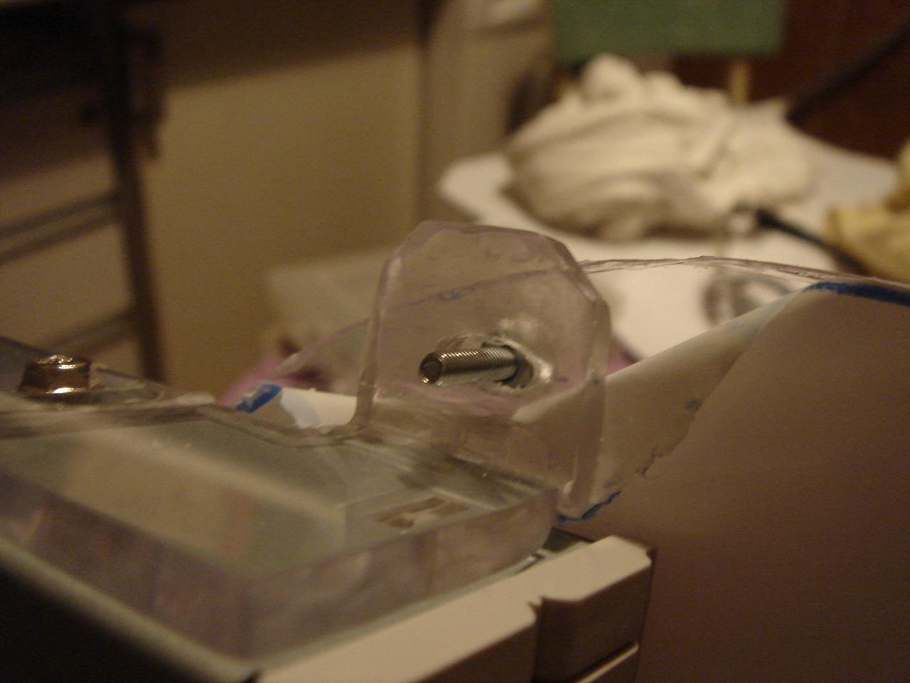
One of the two supports is a pivot, and on the other the disc can move a few millimeters due to the oval hole that allows it to move back and forth.
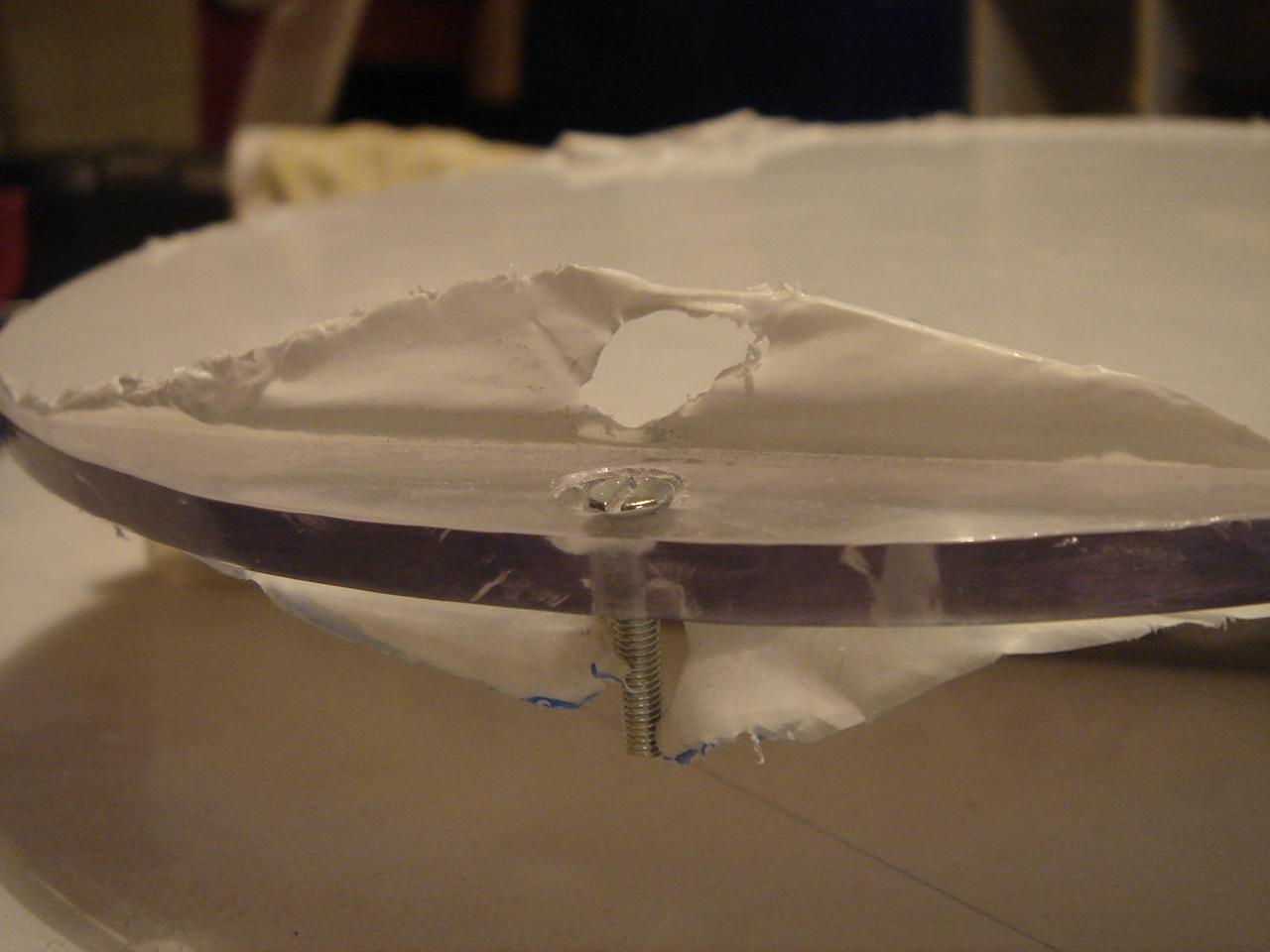
Then, on the disk there is a bolt that presses the drive button when someone presses the disk 😀
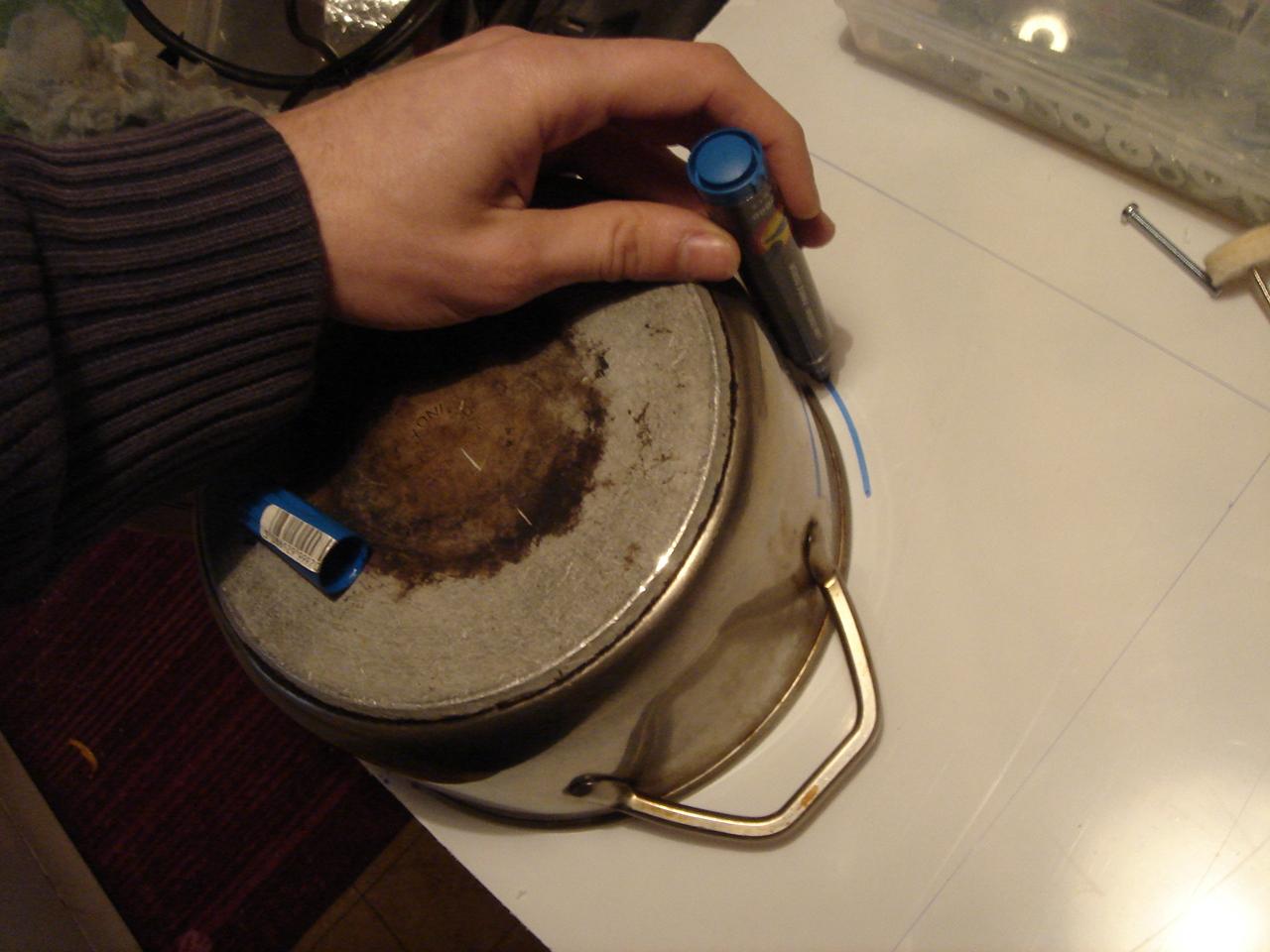
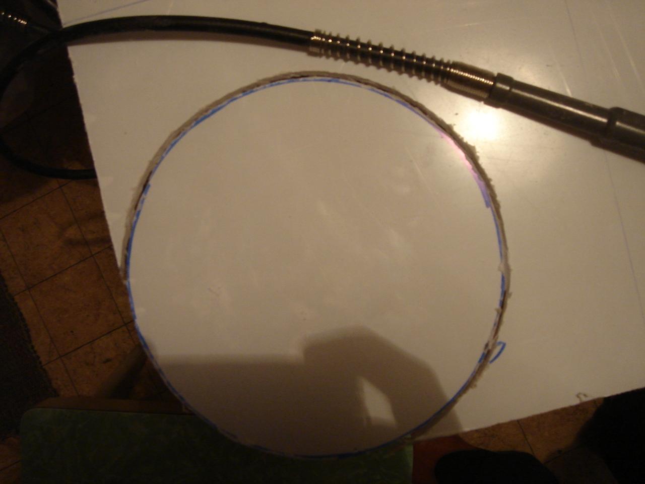
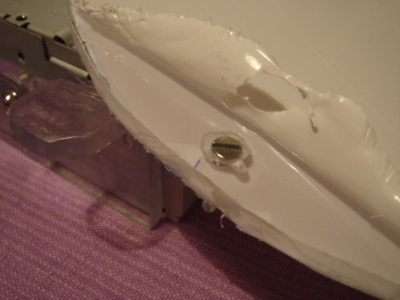
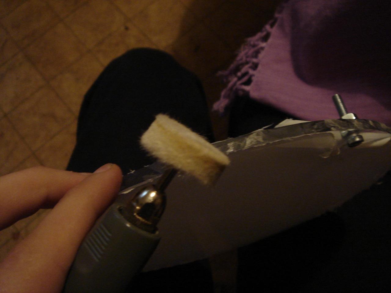
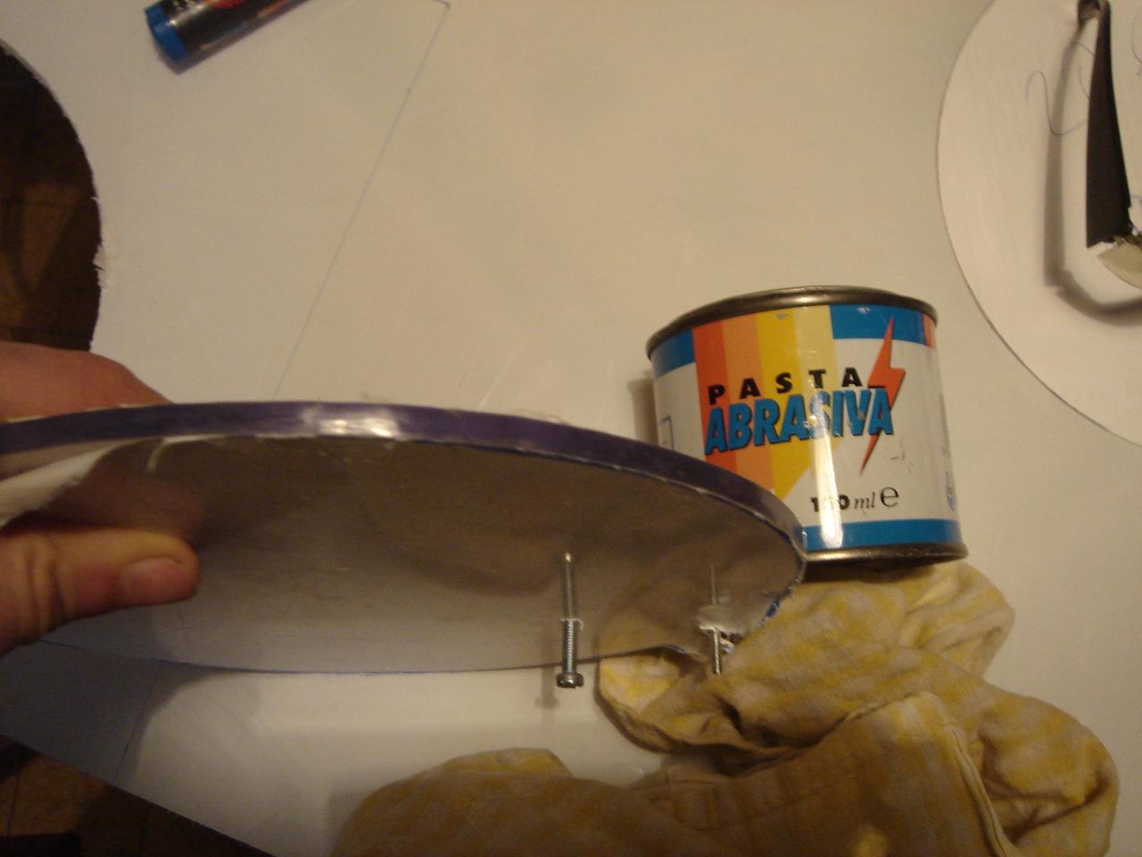
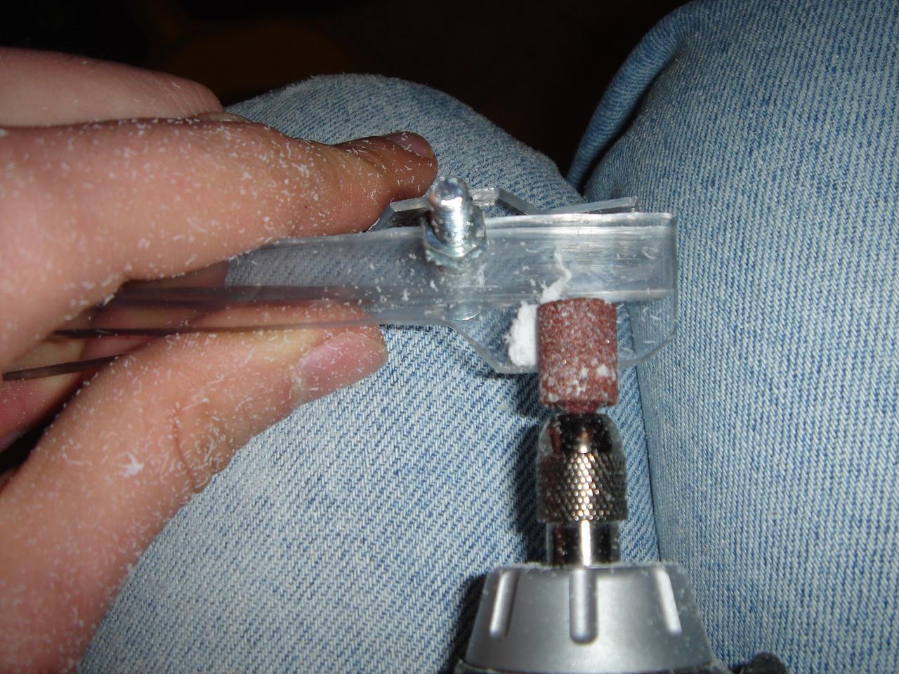
Now it’s time to polish the edge of the disk.
before the polishing:
first pass:
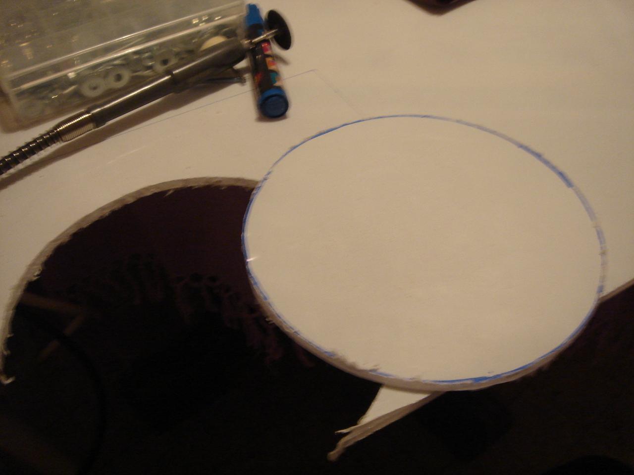
final result:
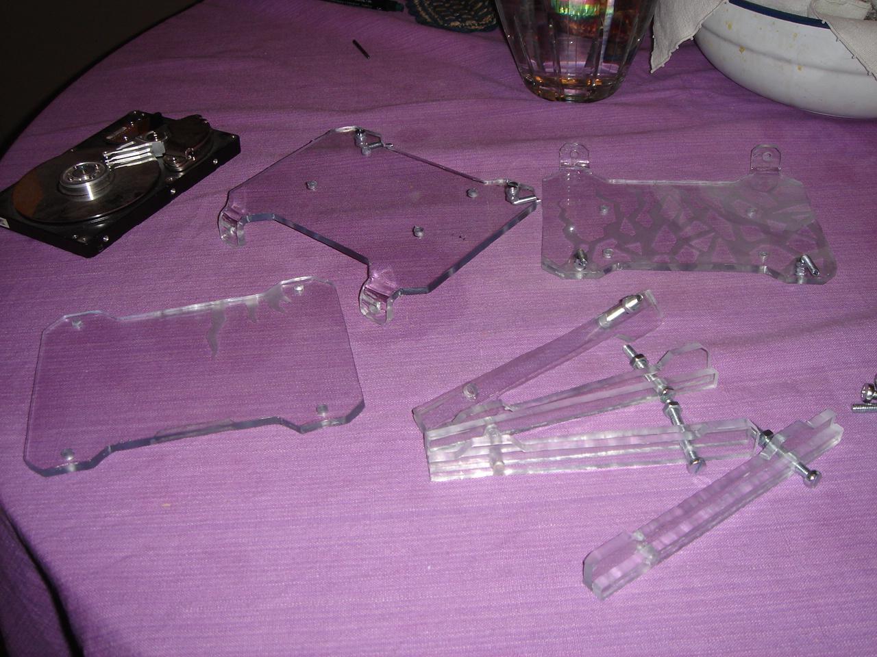
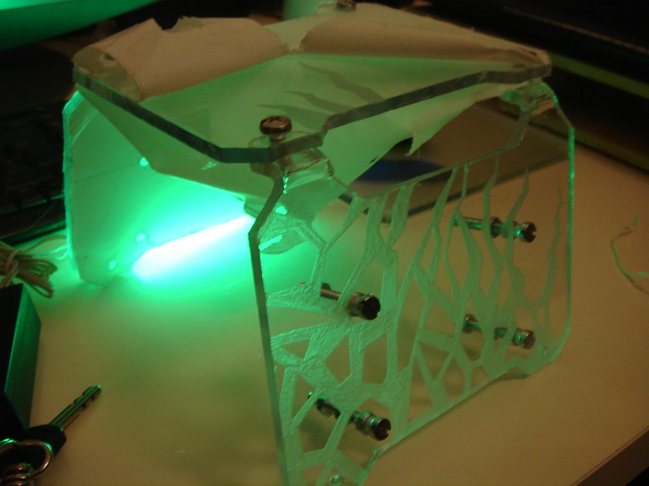
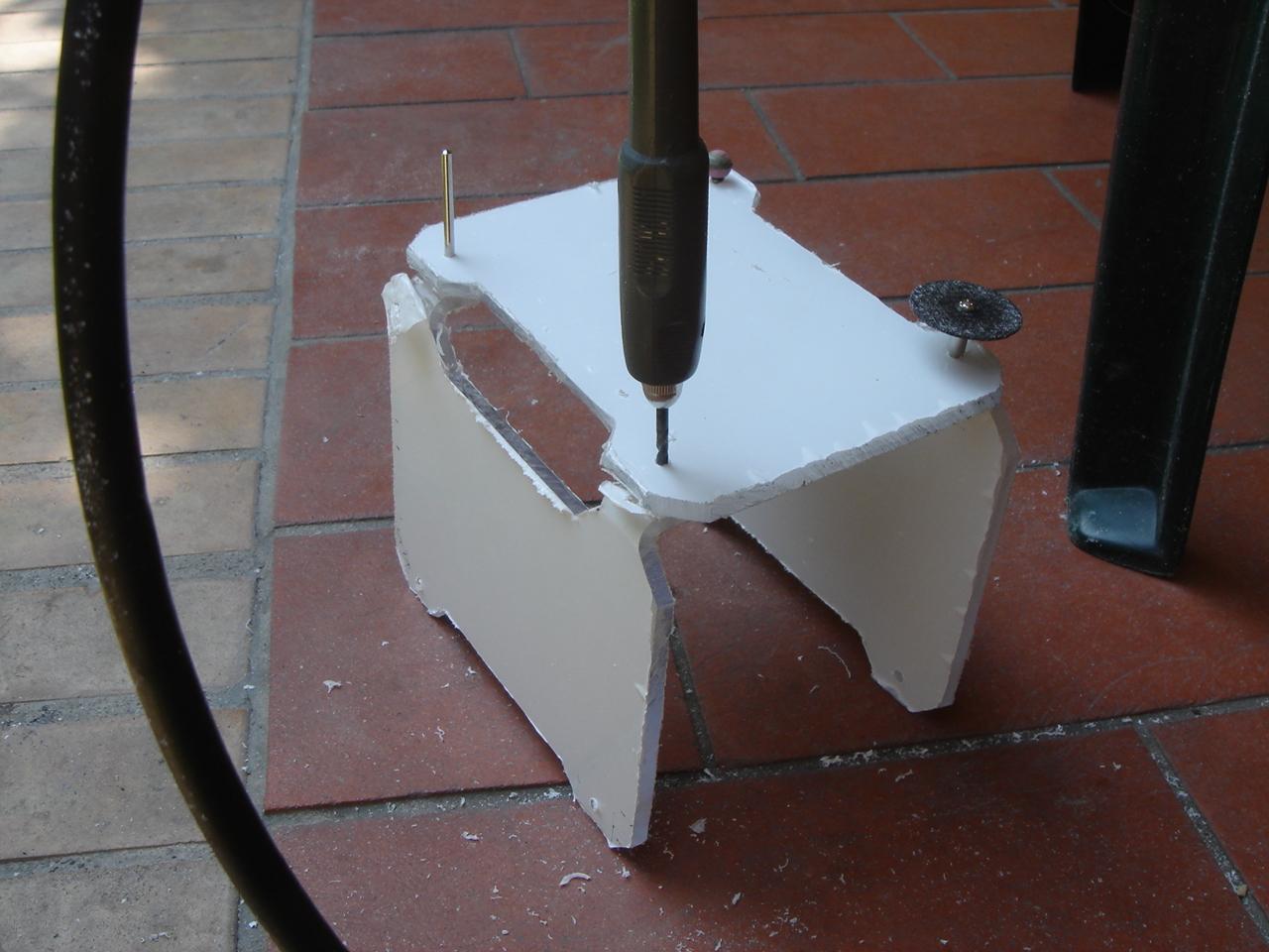
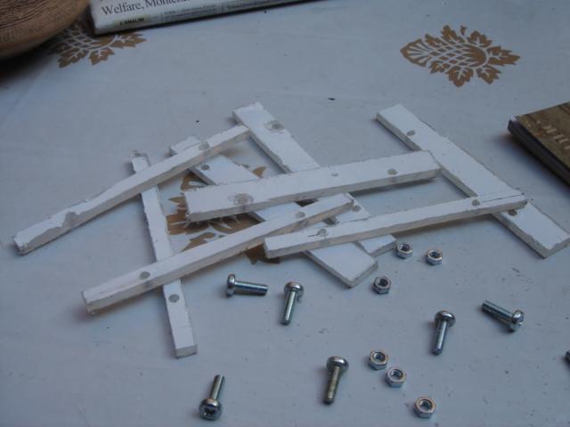
finishing the hard disk structure
I finished the hard disk structure:
I started polishing the edges of the “slides” and the structure:
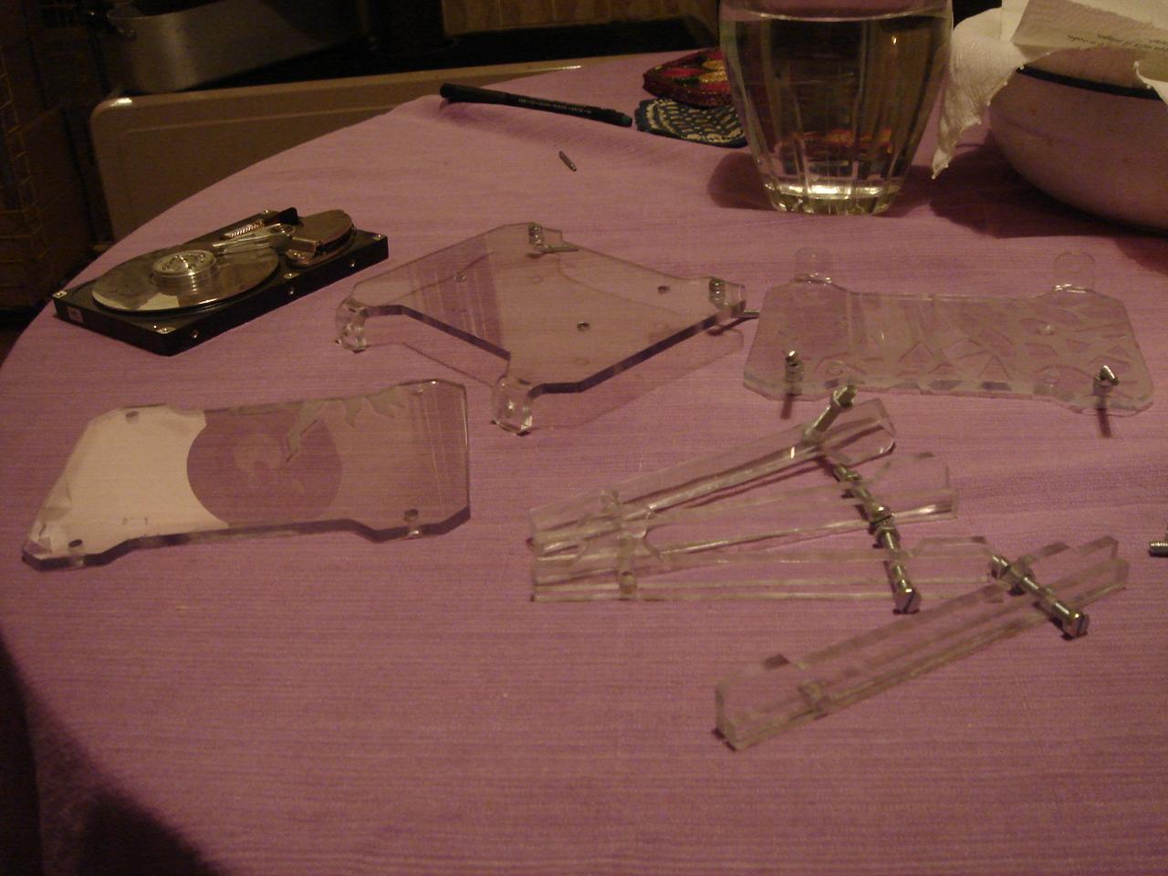
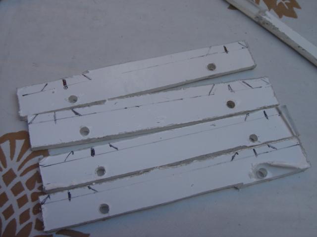
then, I began to assemble the structure:

and I made this holes, to insert the screwdriver when I mount the hard drives:
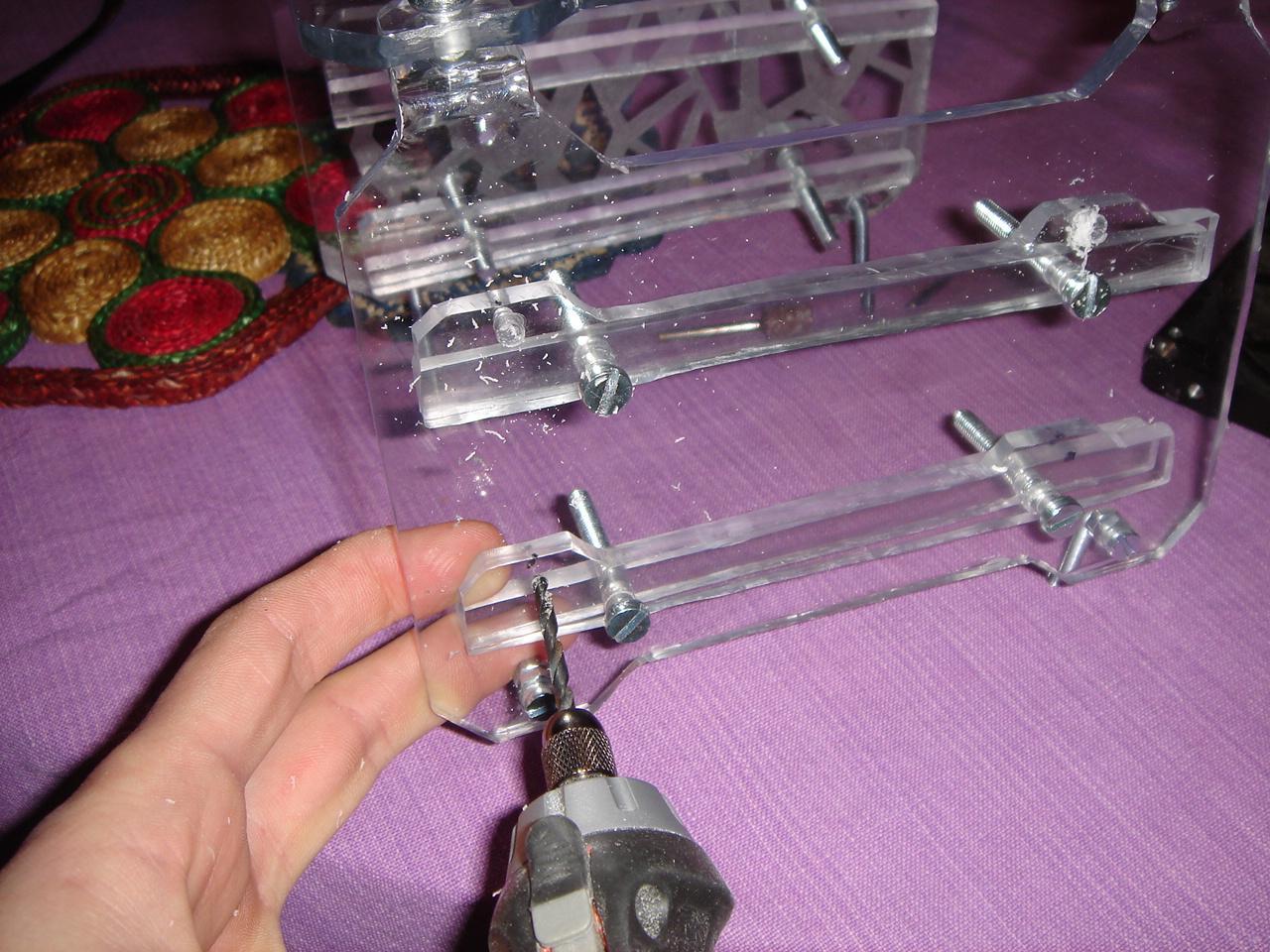
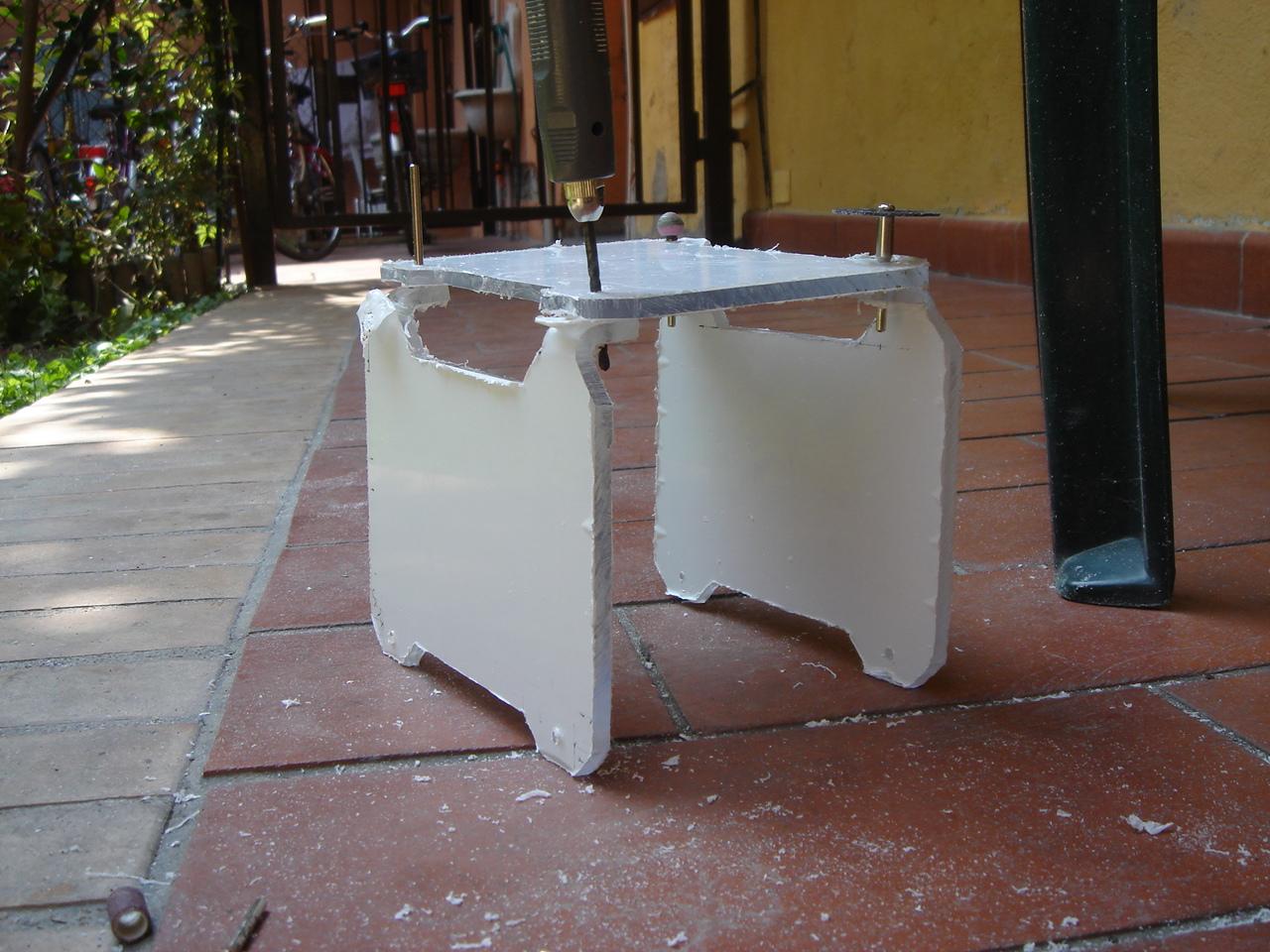
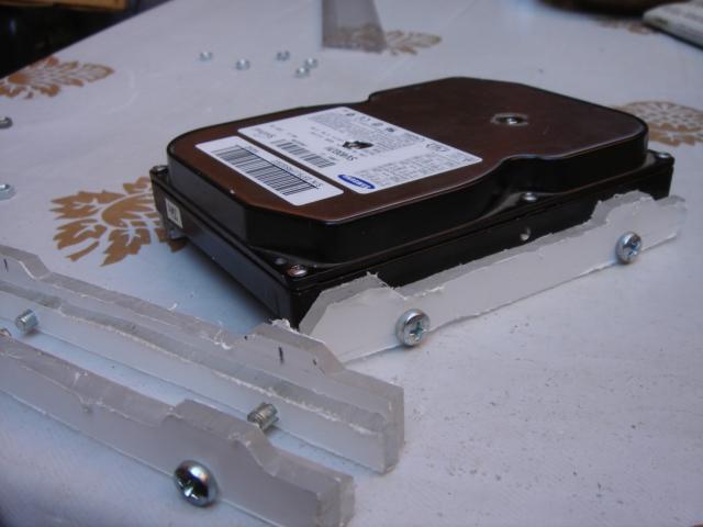
I reduced the thickness of the slides, to mount easier the hard drives:
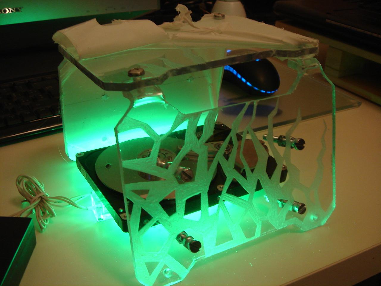
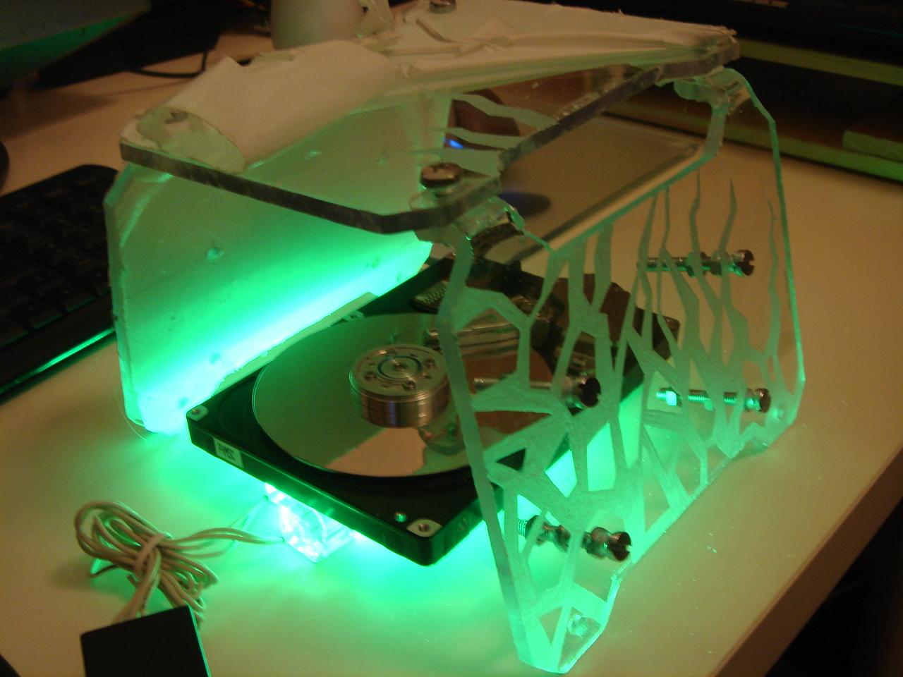
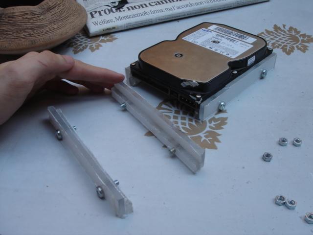
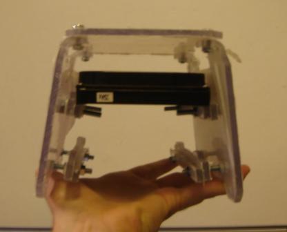
then I mounted the finished slides on the structure:
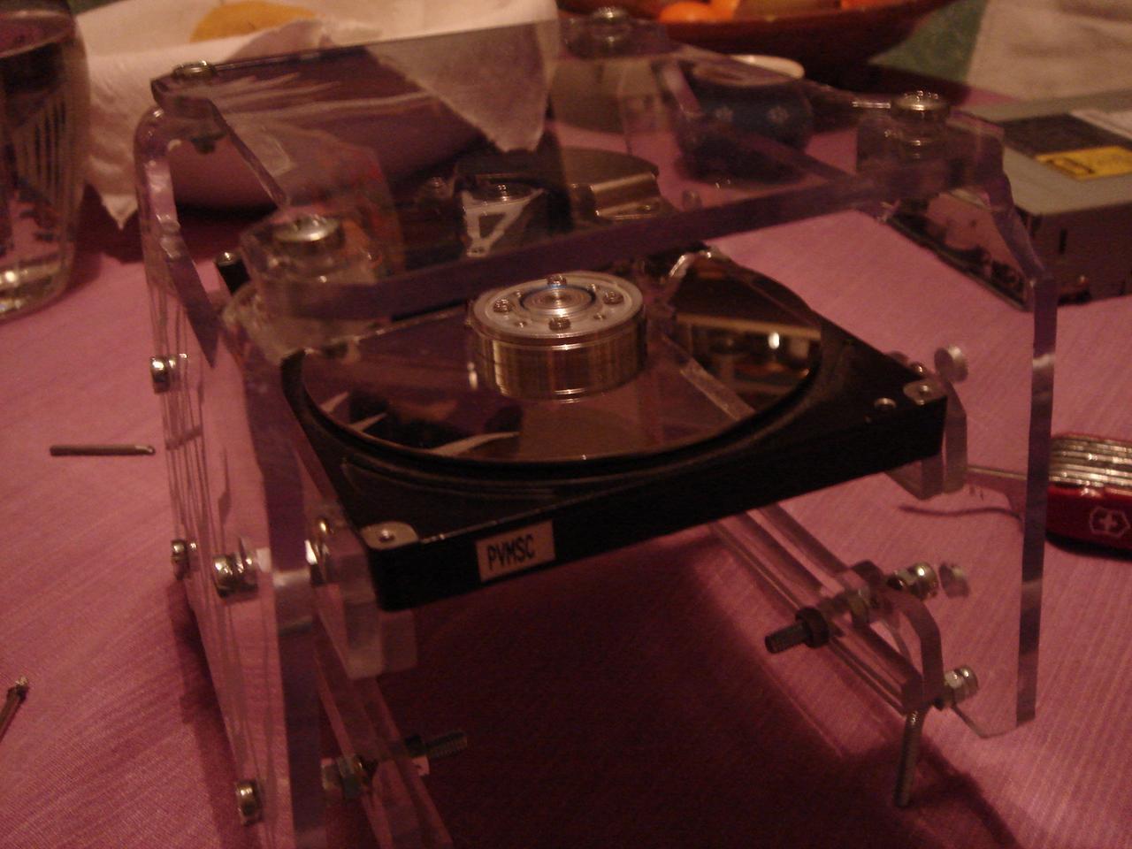
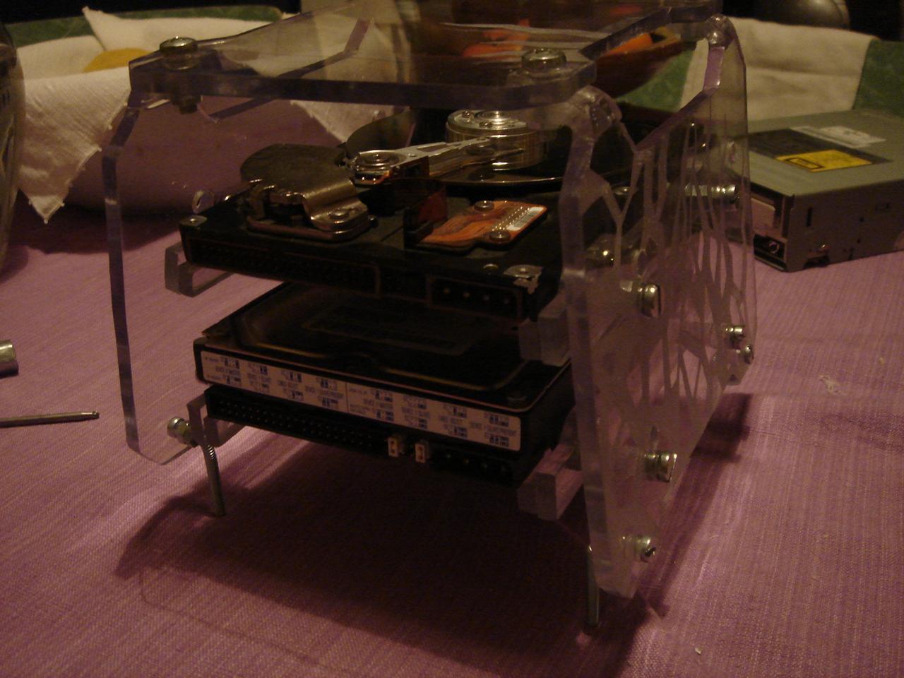
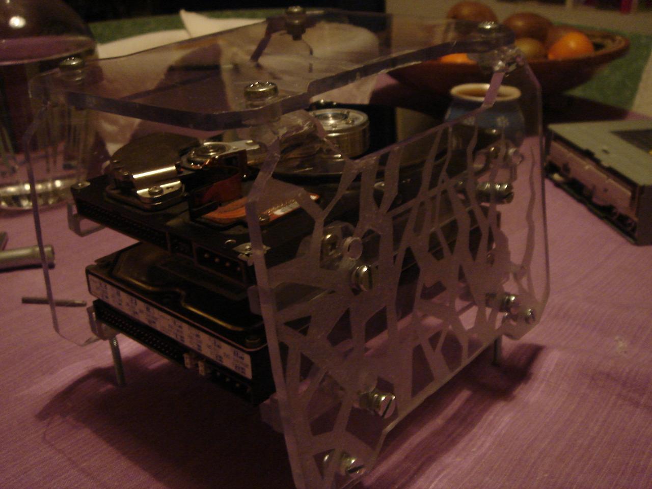
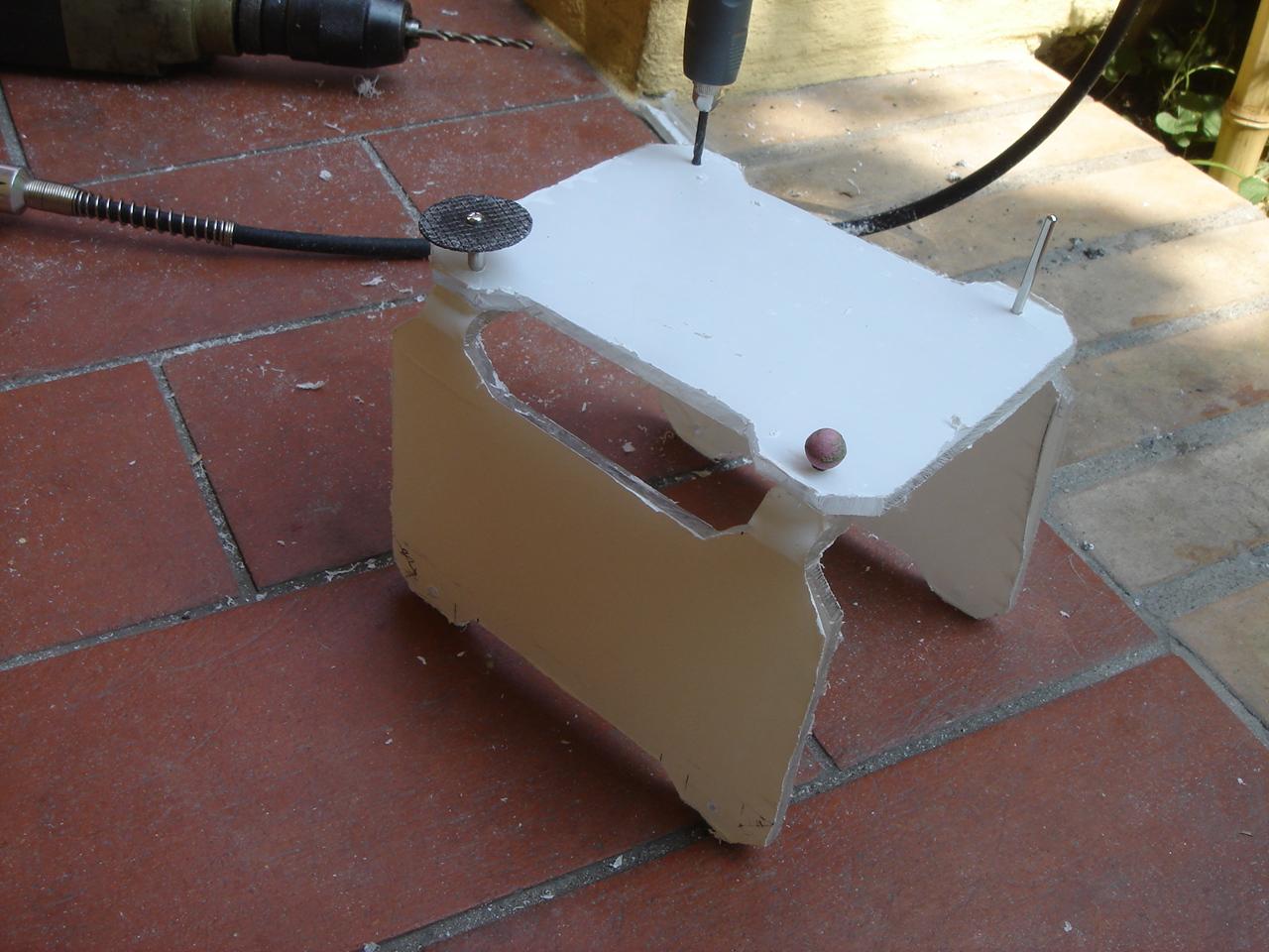
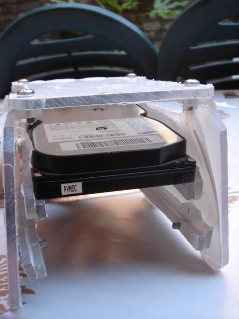
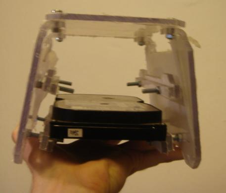
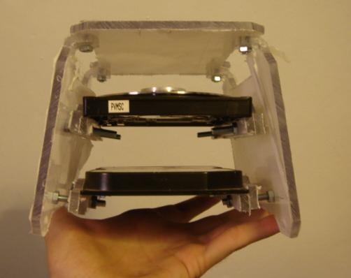
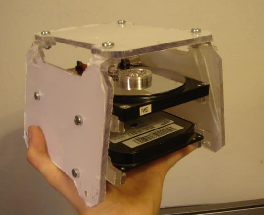
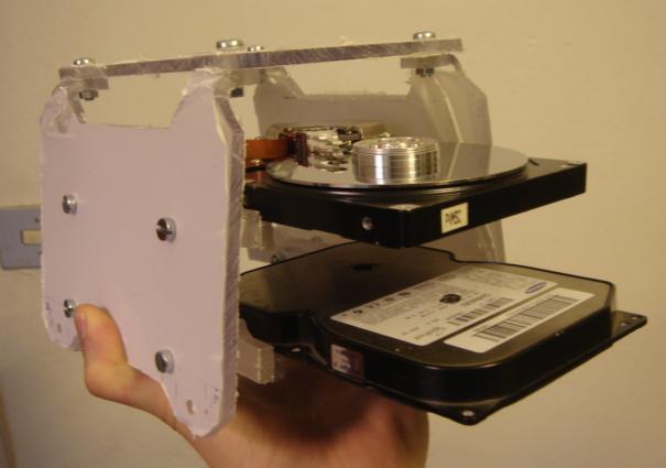
I mounted the hard drives:
and the structure completed with two dummy hdd mounted inside:
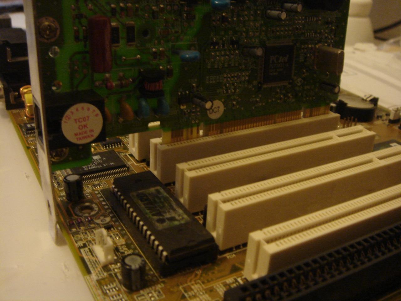
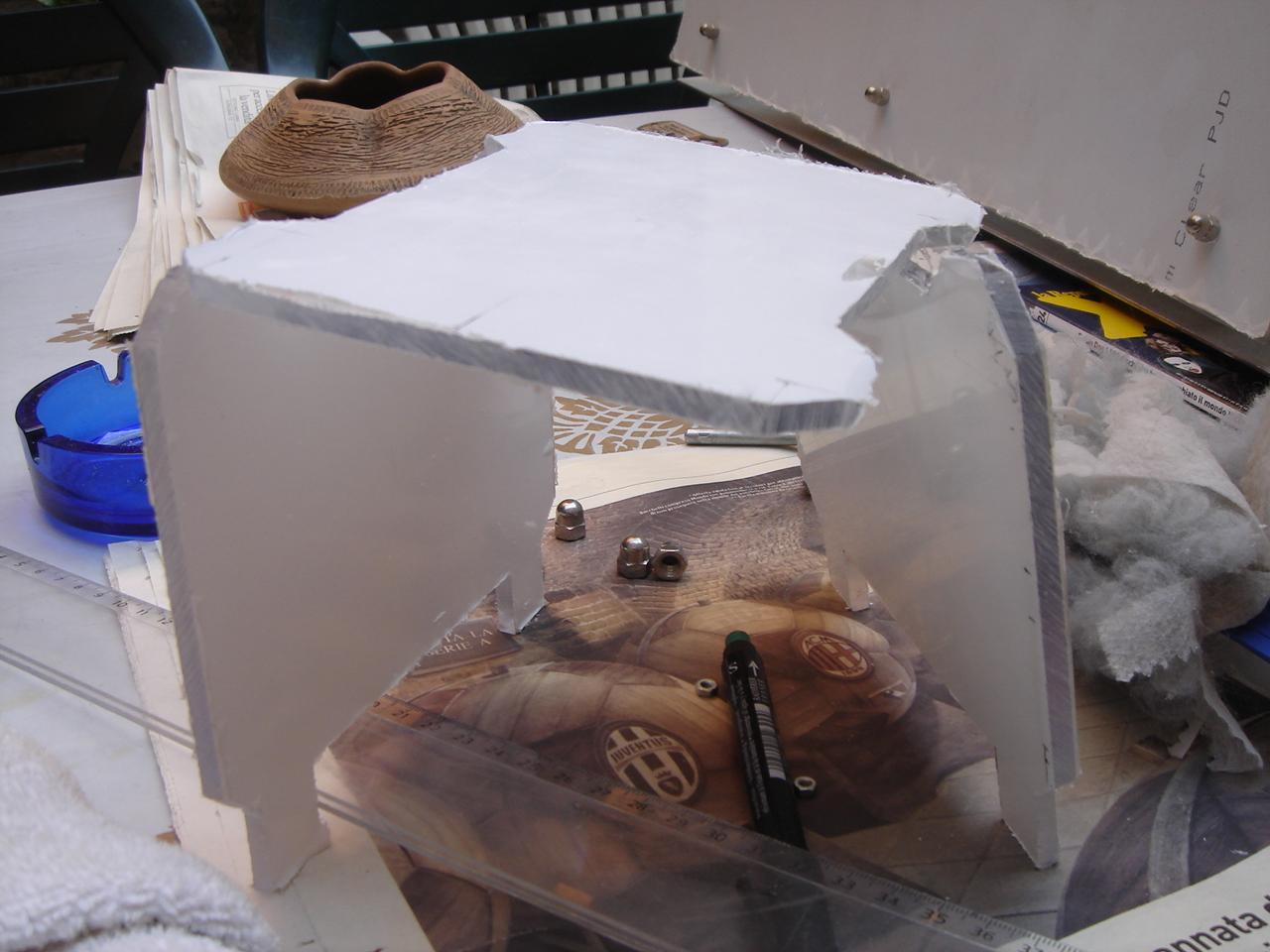
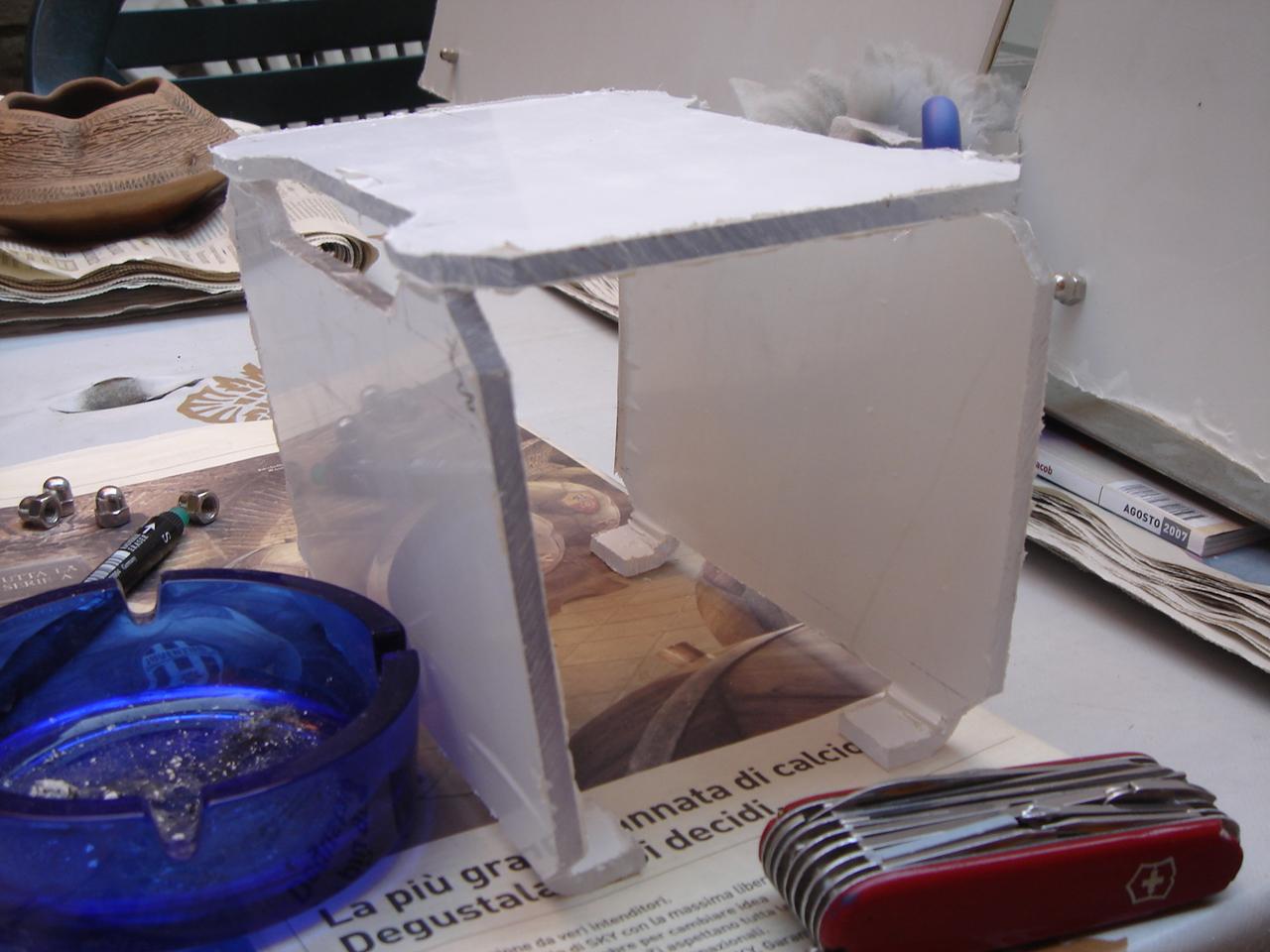
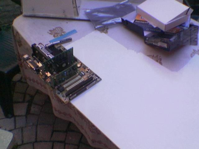
self-supporting structure of the motherboard
I have completed the structure of the support of the mobo, except for the engravings.
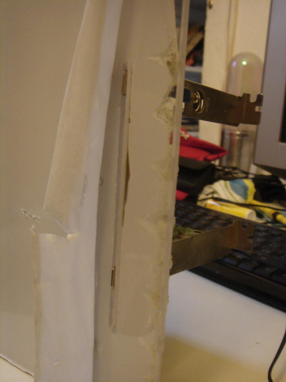
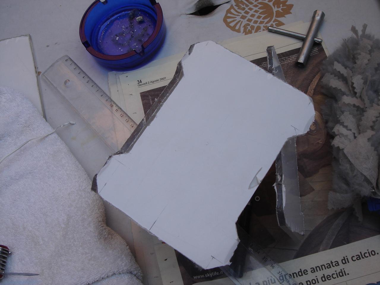
First I had to make a slot in the panel, to put the metal tab of the expansion cards mounted on the motherboard:
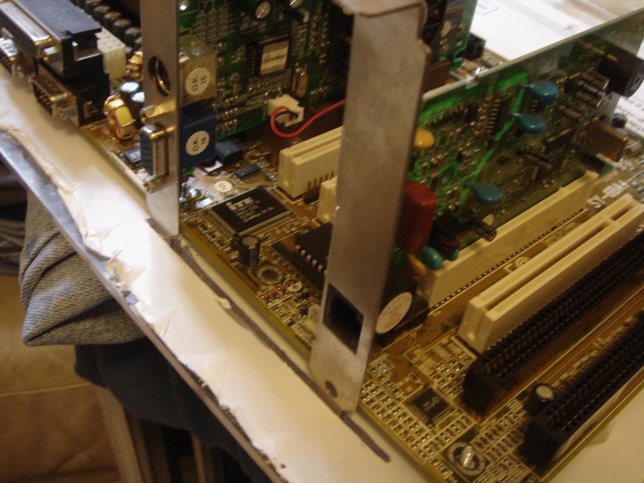
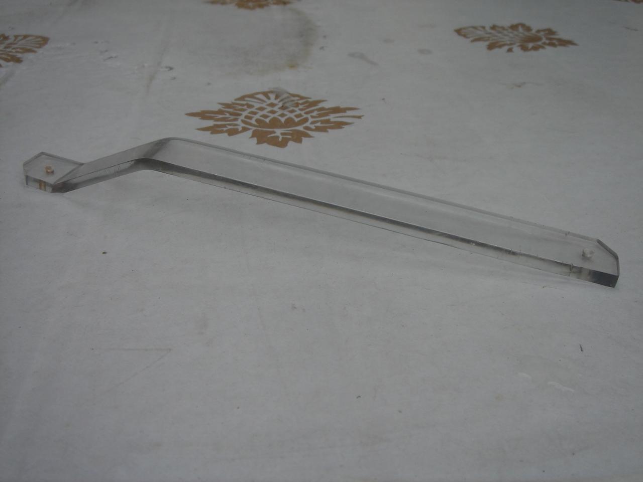
Then I added the support on which are screwed the expansion cards, and the joints to mount the structure on the base:
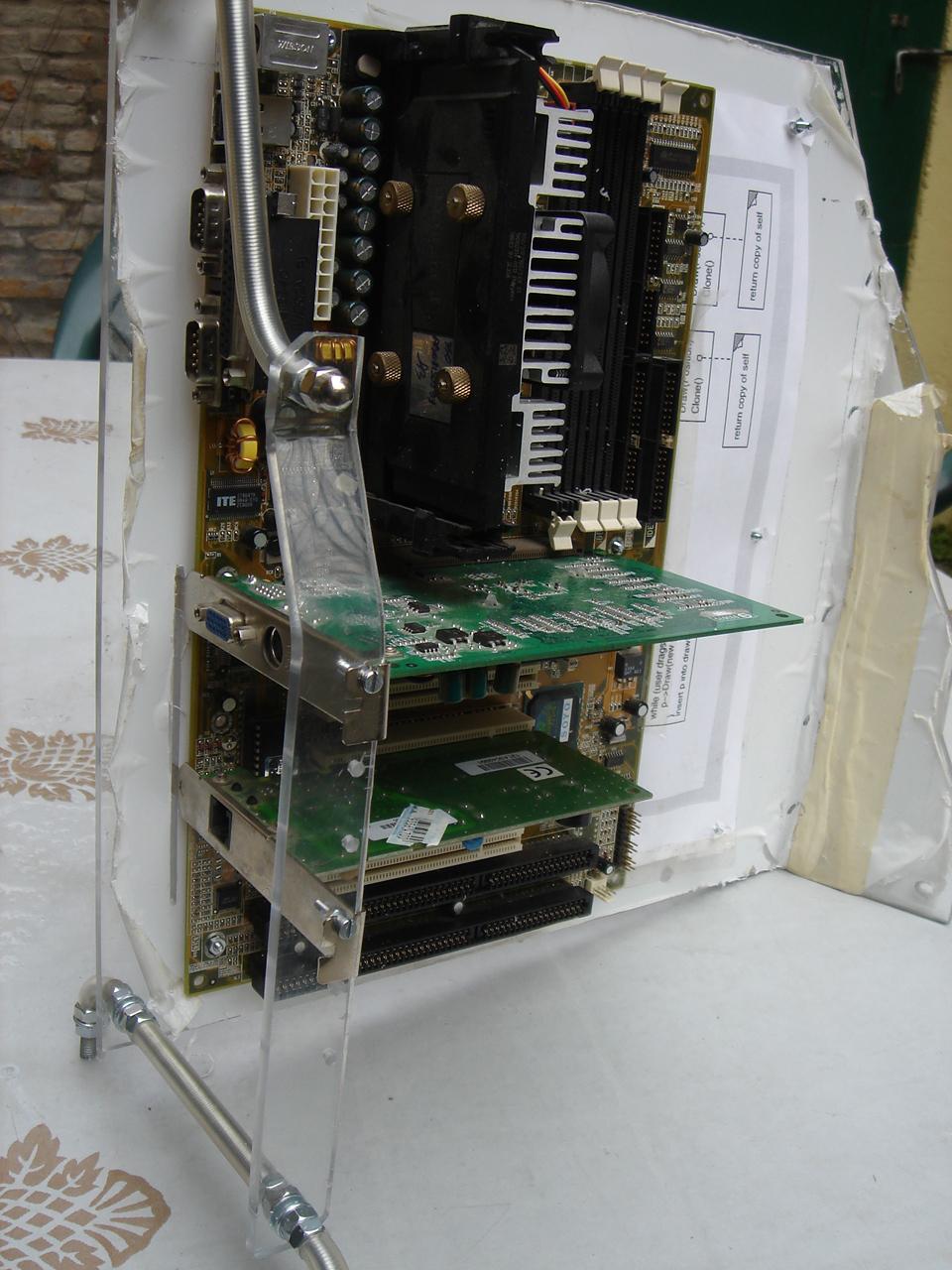
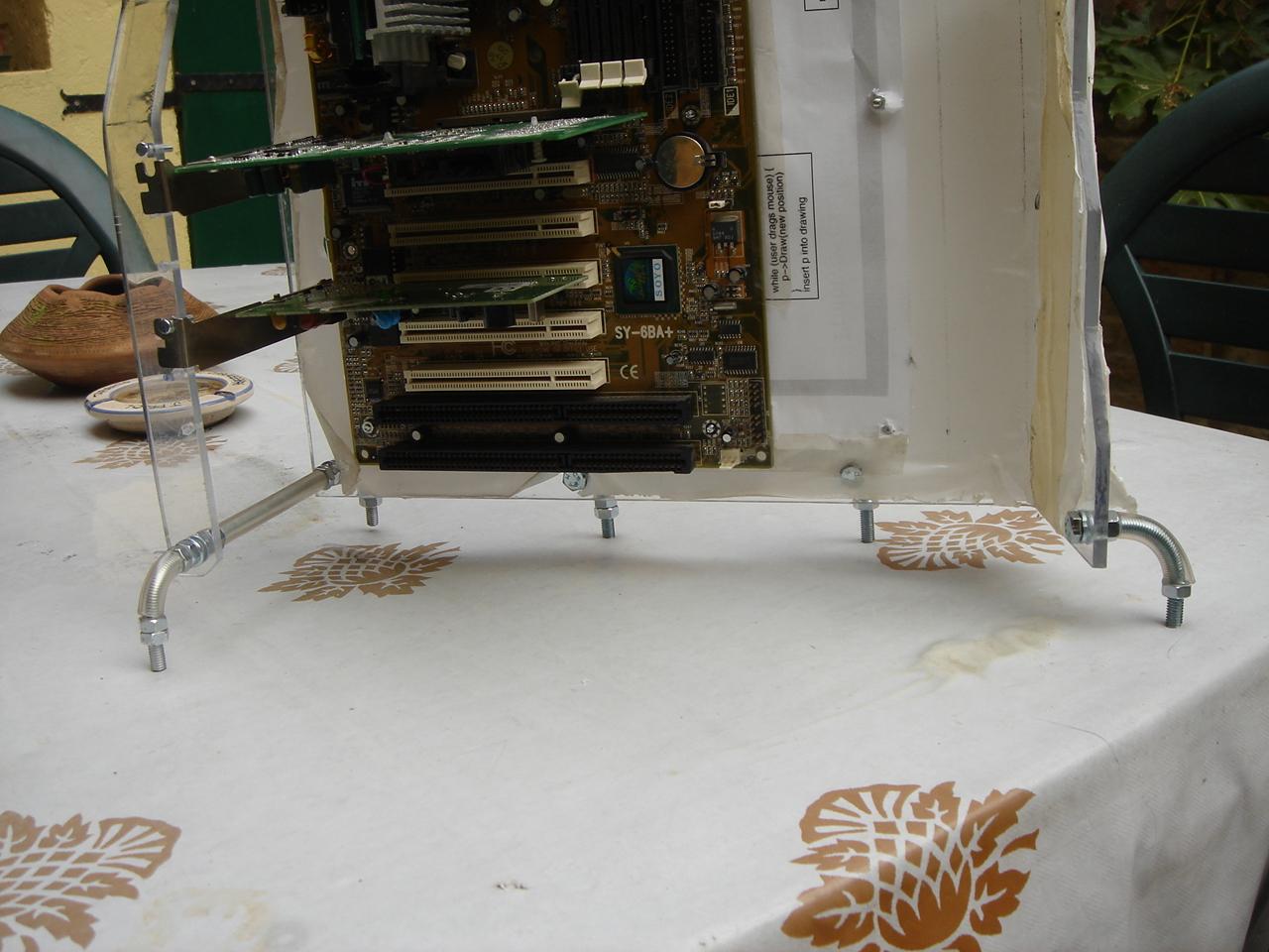
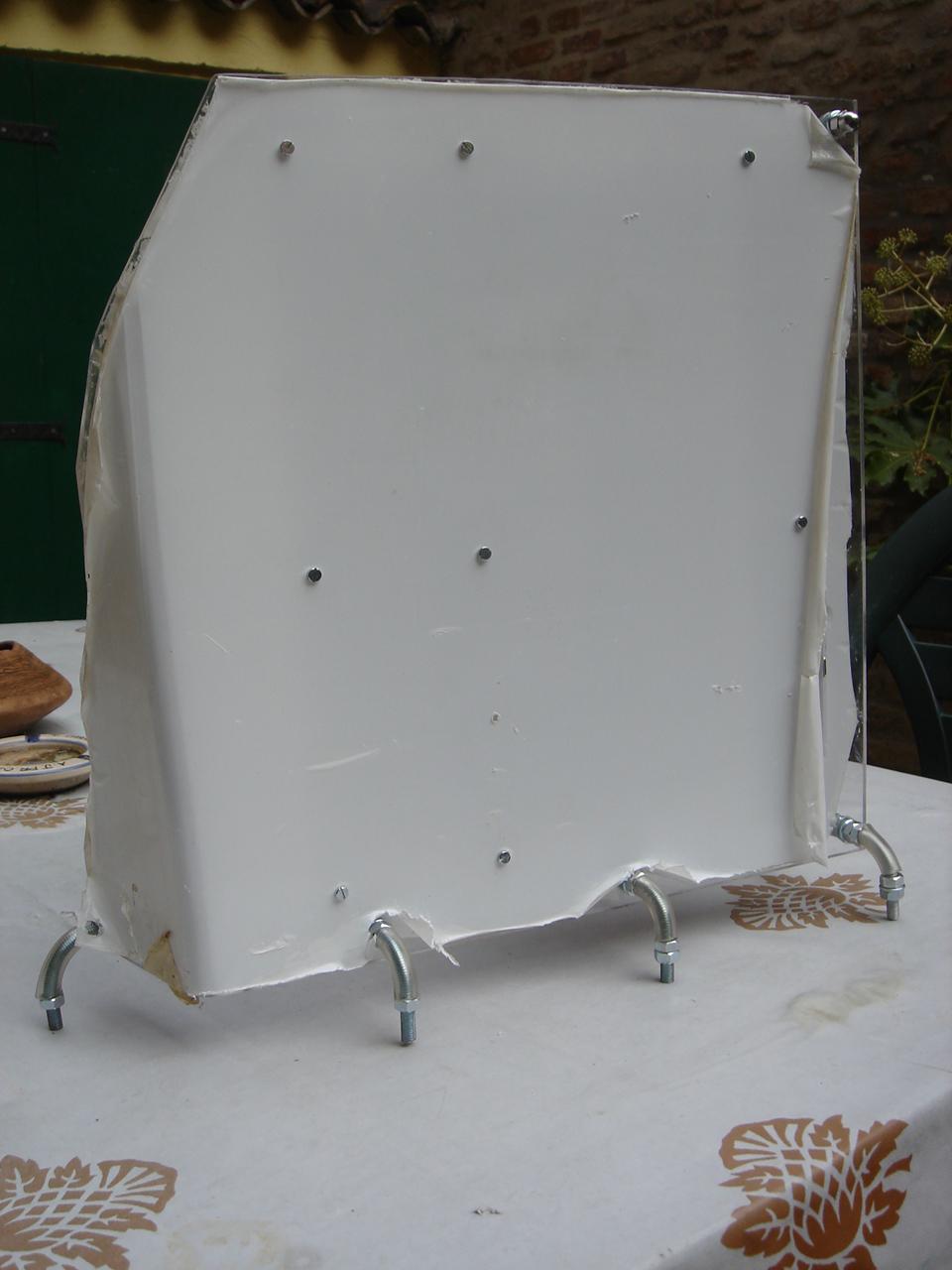
Finally I drill the holes on the base, and I mounted the structure:
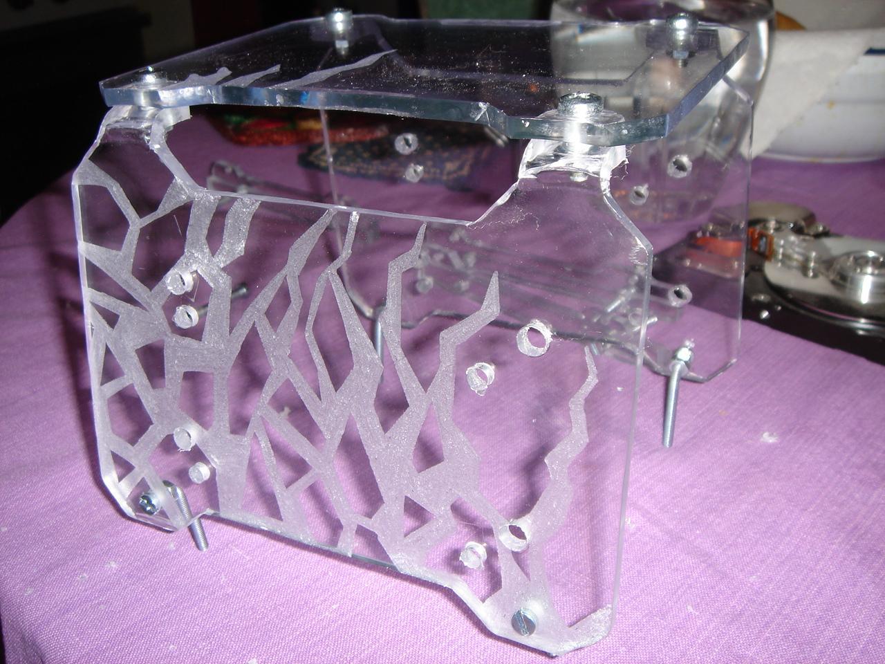
engraving the hard disk structure
The theme for the hdd structure is… obviously the Infected Sector from Tron 2.0 😀 , so the engraving must be a set of green luminous cracks.
After redrawing a lot of times the cracks, I drew some that I liked, so I engraved them:
then I tried the effect of the green luminous cracks:
hard disk structure
At this point I start to build the last of the components of the basic structure: the hard disk structure:
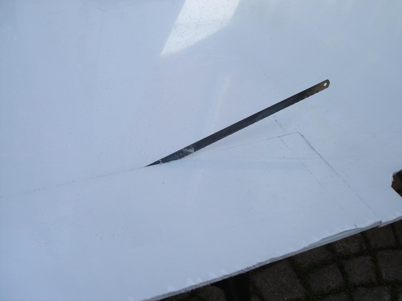
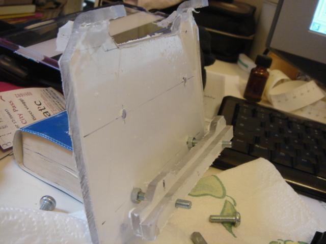
When i bent the shaped panel I broke it! 🙁
At this point, I must find another way to keep the 3 pieces together 🙁
And this is the other way: I have flipped upside down the lateral panels, and I have fixed them to te top panel with some bolts
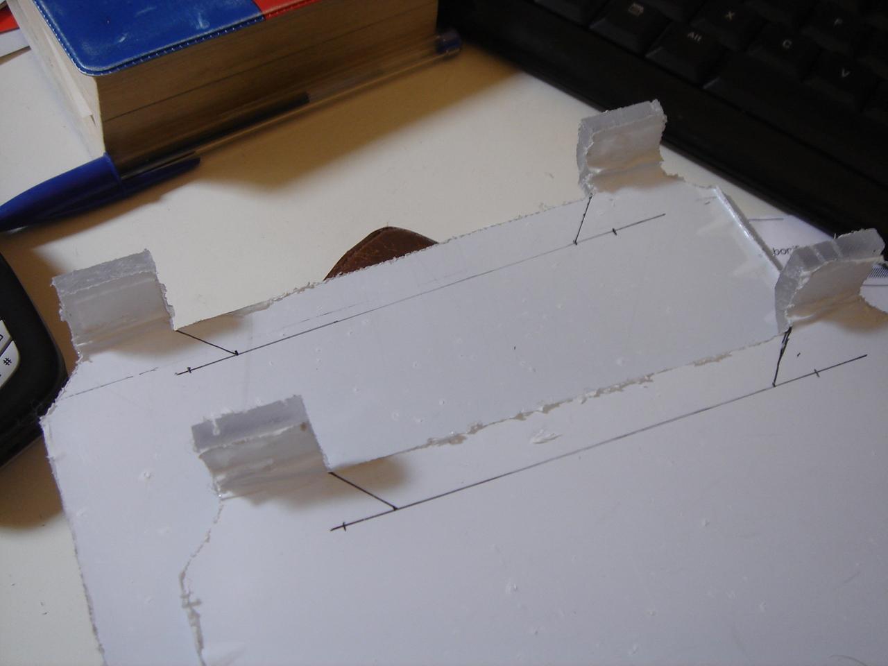
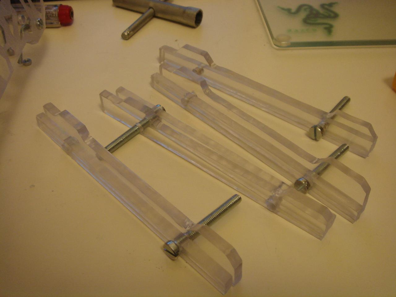
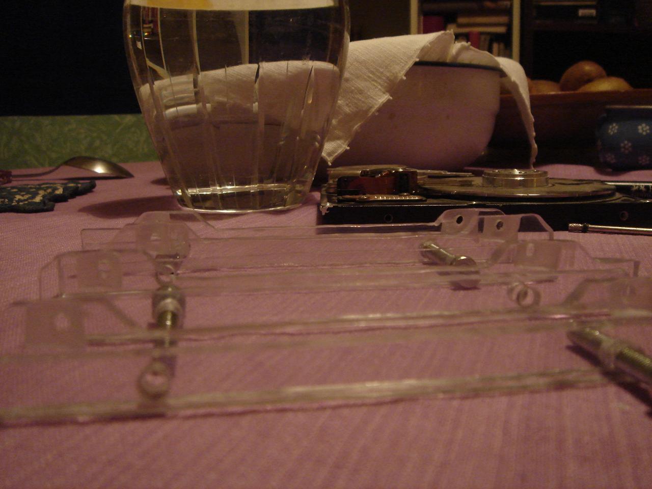
And now, the slides for the hard disks.
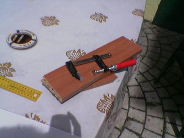
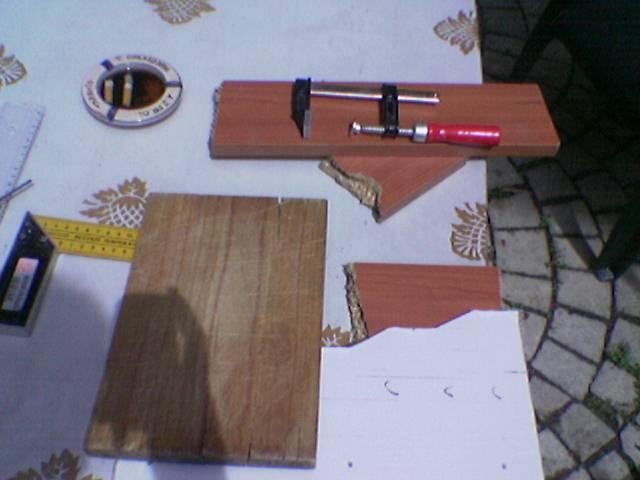
I cut the pieces:
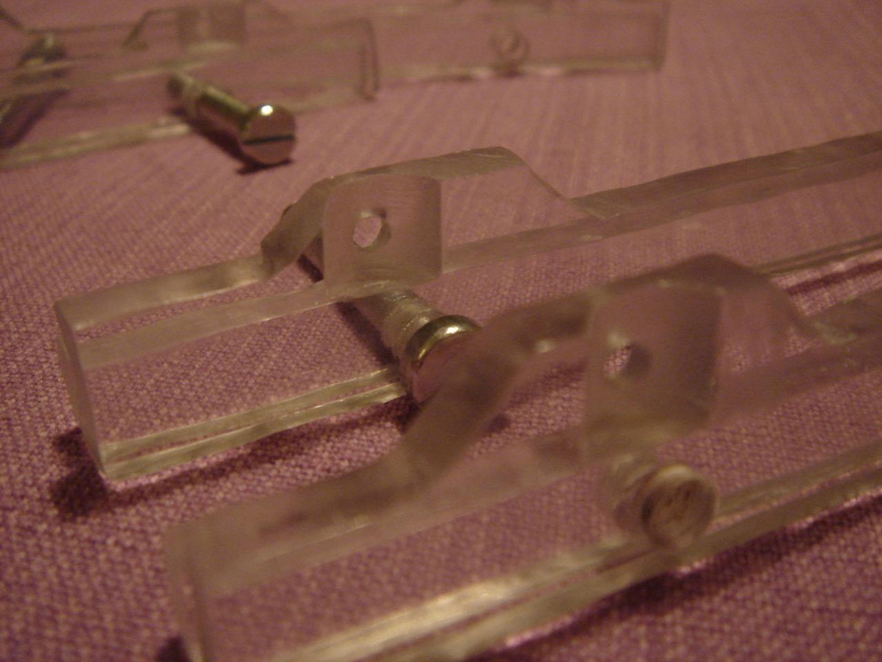
I assemble the pieces together:
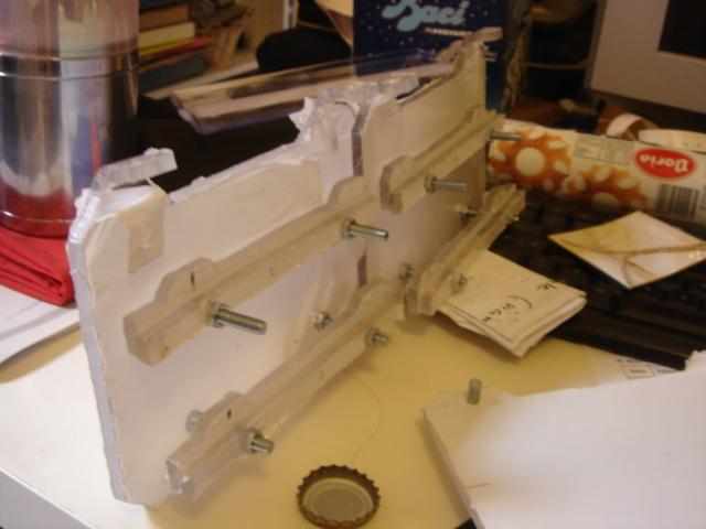
In the last image you can see that the slides below are closer to each other than the ones above.
This is because the hdd structure must be trapezoidal like the rest of the case!
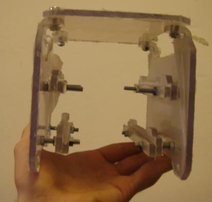
The slides are as long as the hdd, so you can insert and extract it like a drawer:
bending the motherboard structure
and now the troubles begin… 😀
at this point I should have had to bend a side of the panel, but I couldn’t do it and I got hurt in the various attempts.
First I have done a mild attempt
…failed:
then I used a little more strength…
result: failed (and a broken cutting board)
then I used more and more strong methods:
…failed
after this attempt, with a broken board and a crushed and bleeding finger, I used another bigger chopping board!
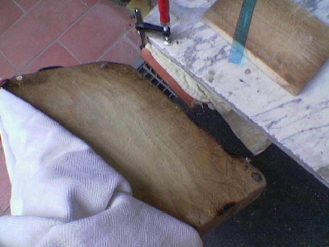
…failed
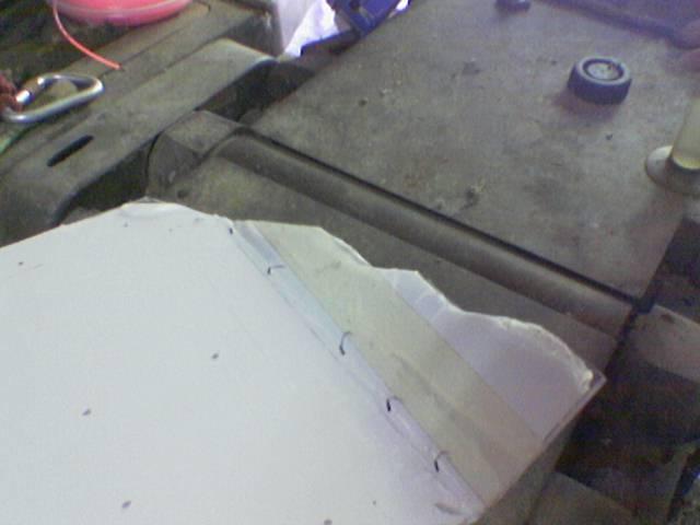
result: polycarbonate that did not bend at all, and some scratches in the bending area:
But finally I have won my battle against the polycarbonate!
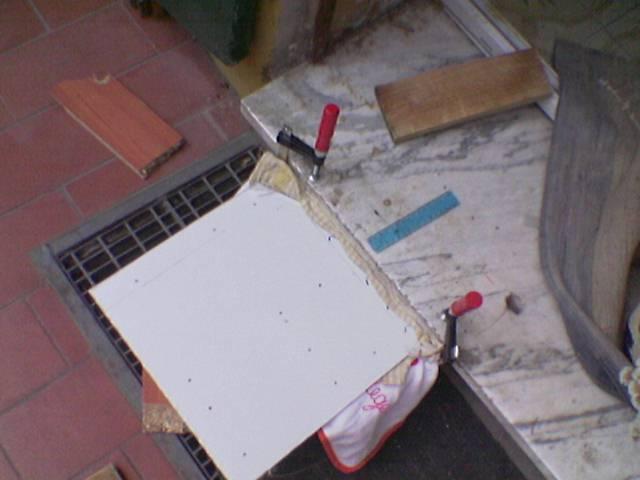
How I have done:
first I put it in a vice with a robust wood board, then I went on the board with my full weight, to obtain a first bending.
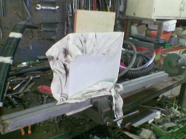
then, given the first bending, I placed the panel in the gap of a wood planer (about 1 ton of weight), which has been stronger than the chopping board! 😀
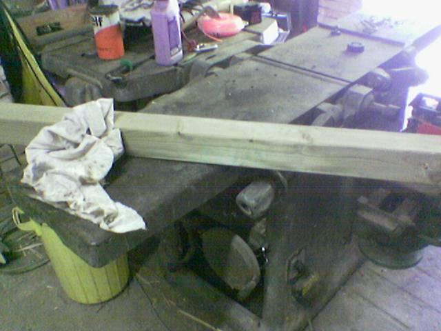
the wood planer:
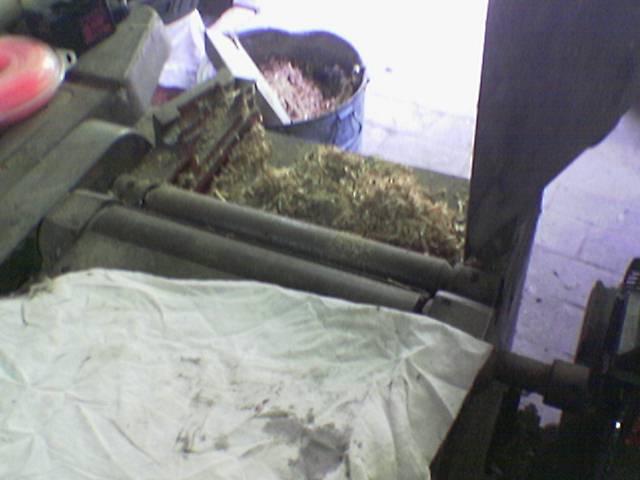
I fit the panel in the wood planer:
the locked panel:
the wood board on the panel:
Then I and my father went both on a wood beam placed on the panel, and our weight combined has done the magic!
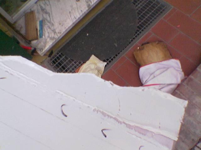
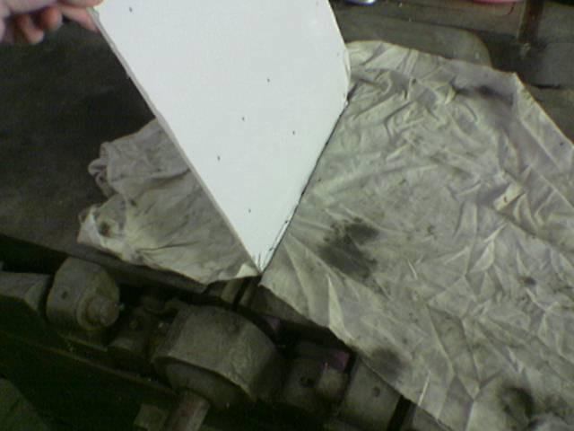
and finally the bended panel! 😀
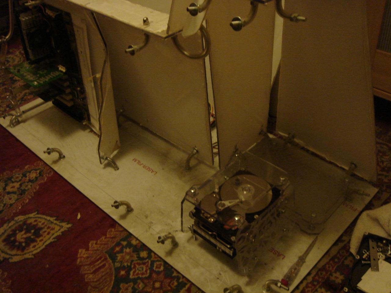
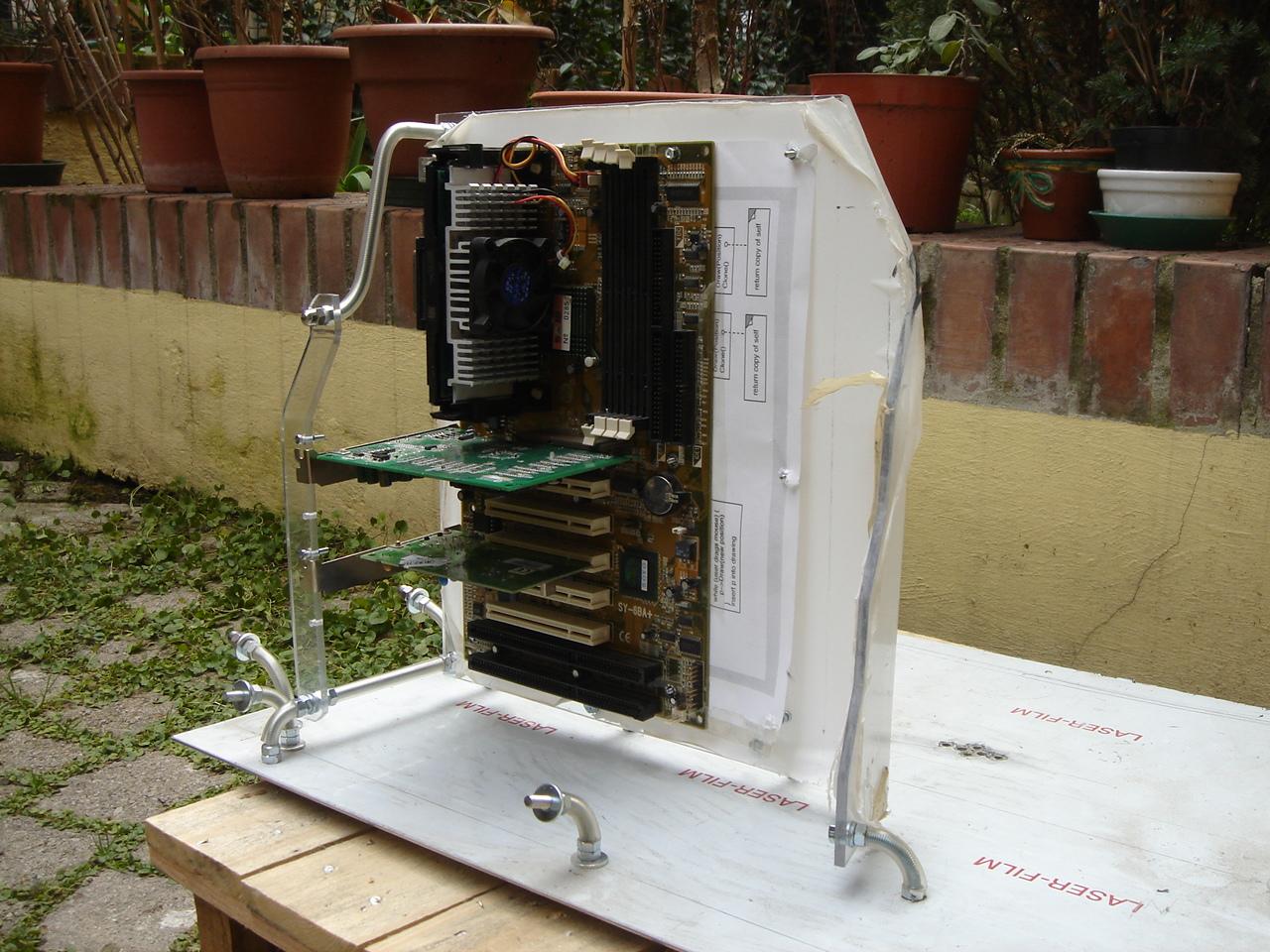
Then I mounted a dummy motherboard on the structure (the paper sheet simulates the 24.4cm width of a full-atx motherboard):
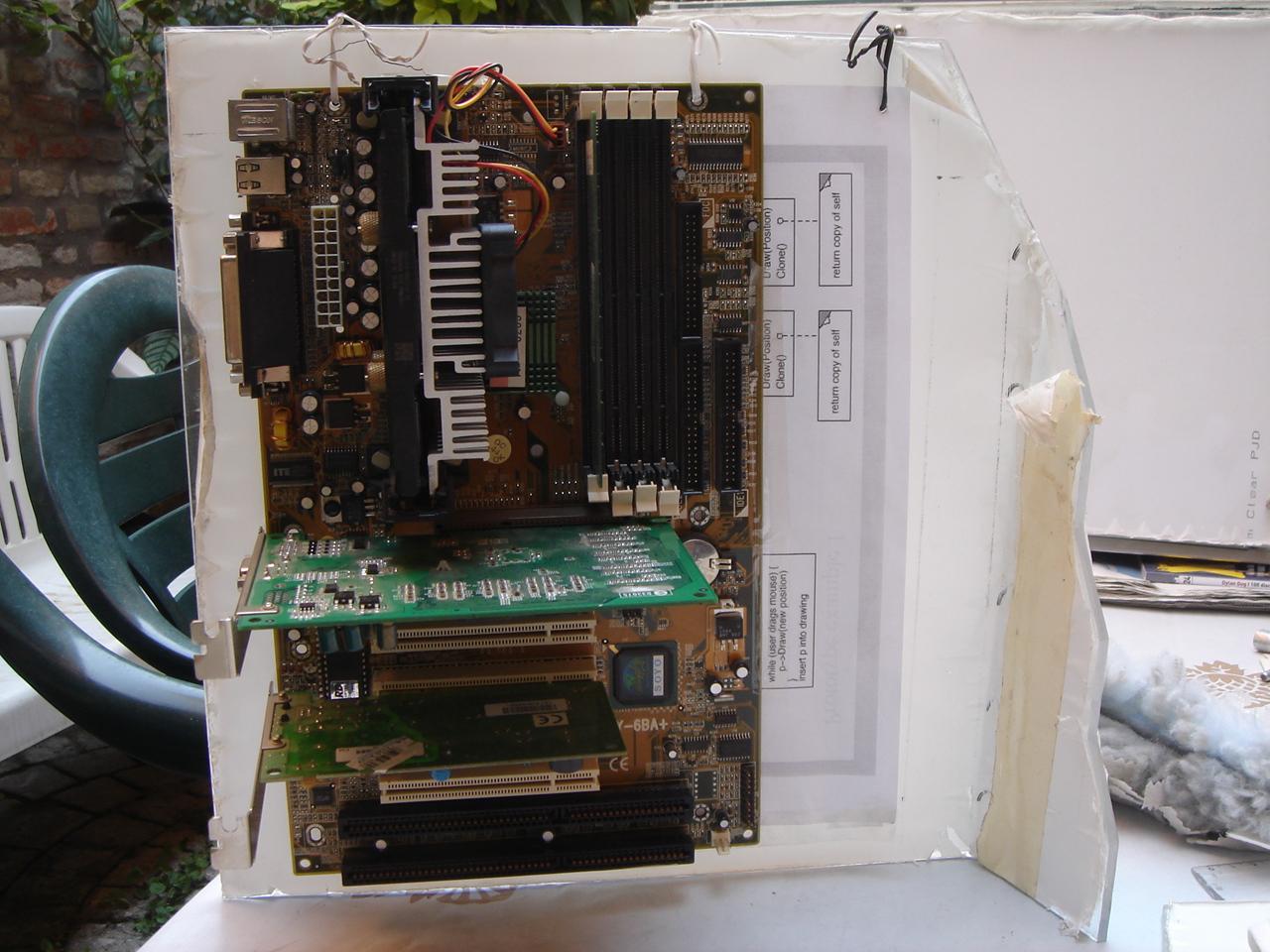
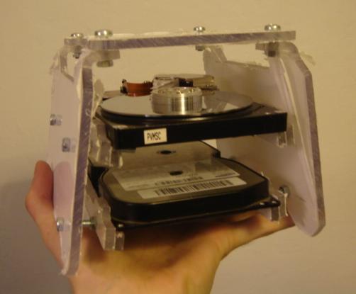
…and I placed the dummy components in the case (the box of the camera should be a dummy 2 hdd structure, and the mysterious component under the shirt is… the mysterious component 😀 )
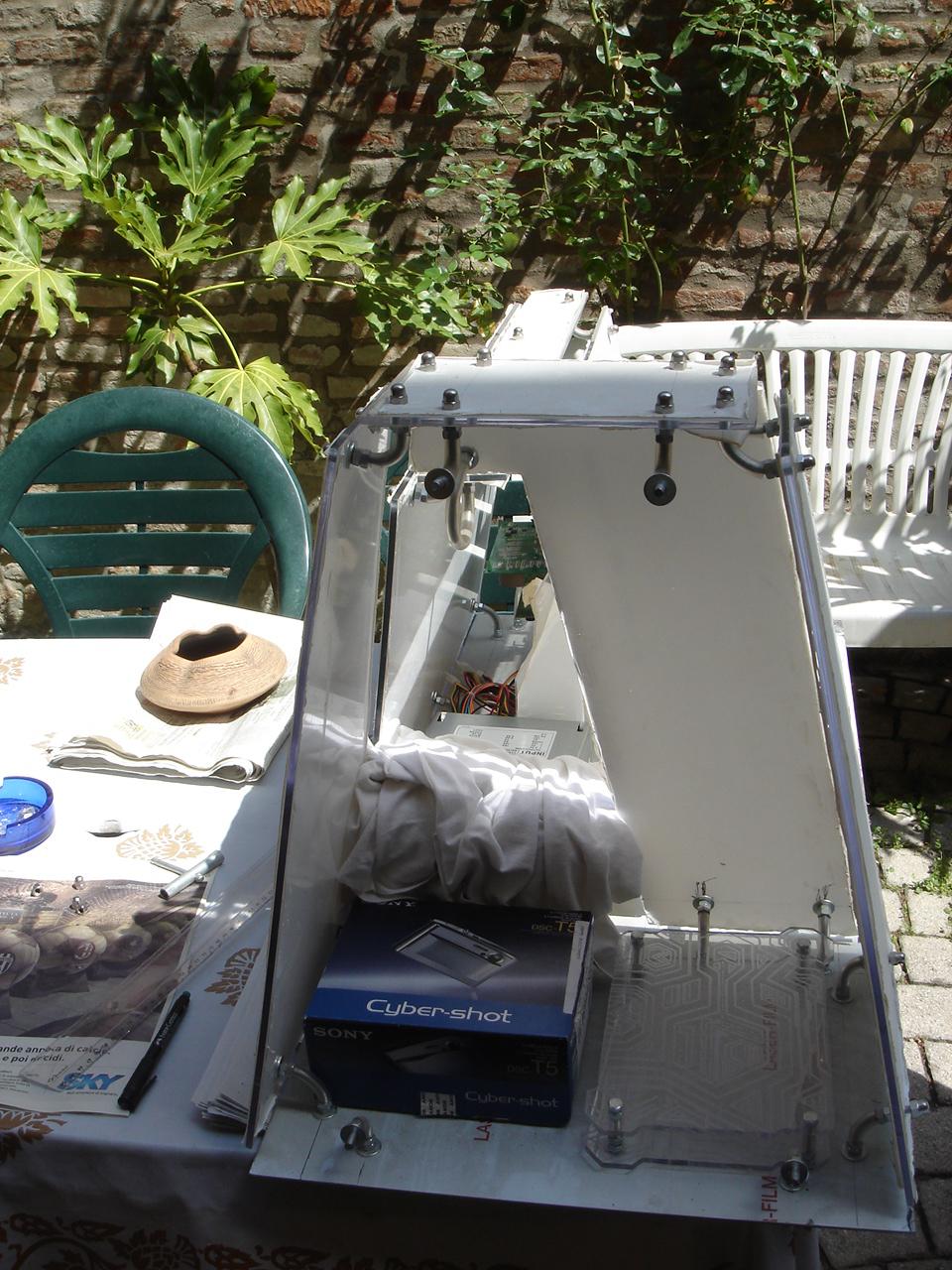
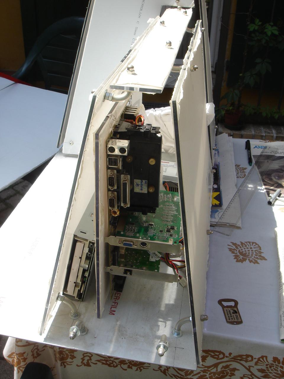
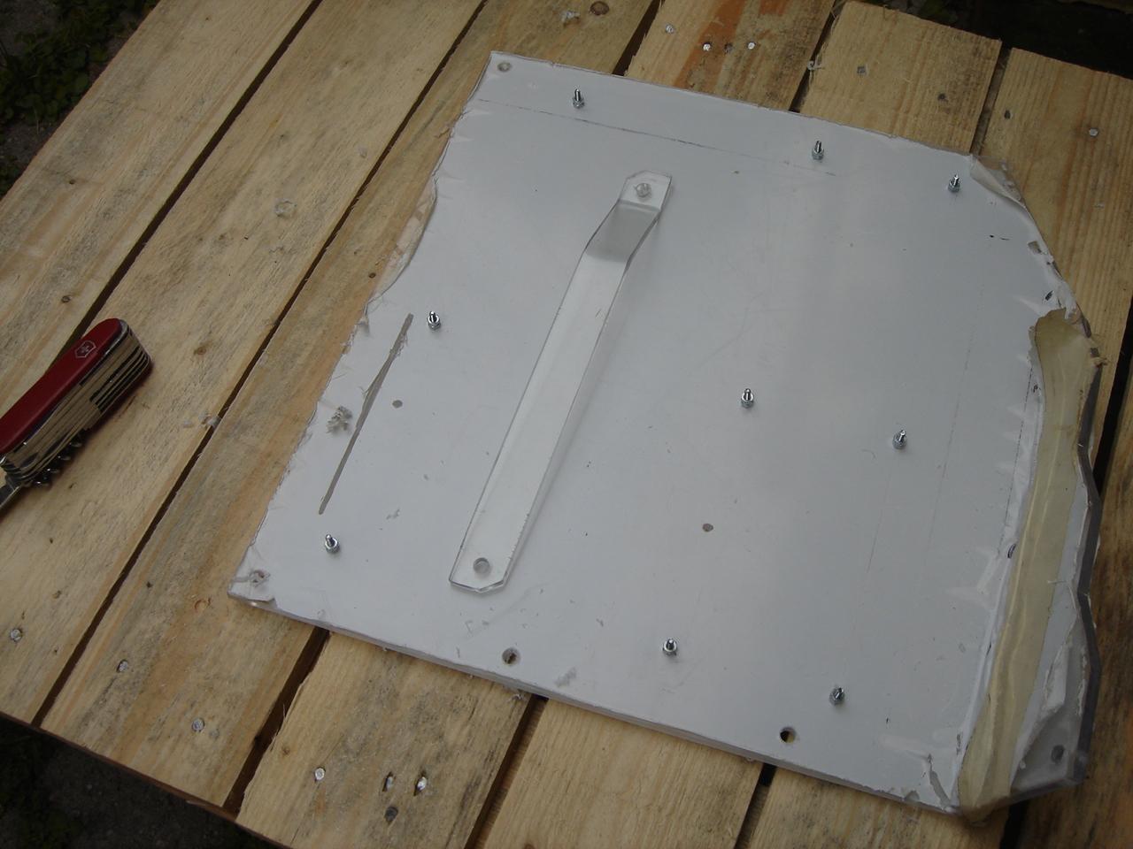
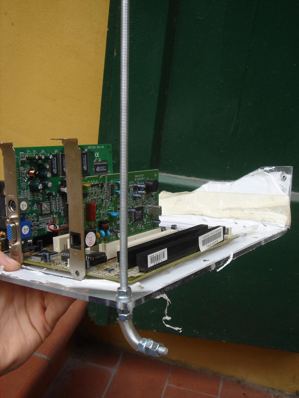
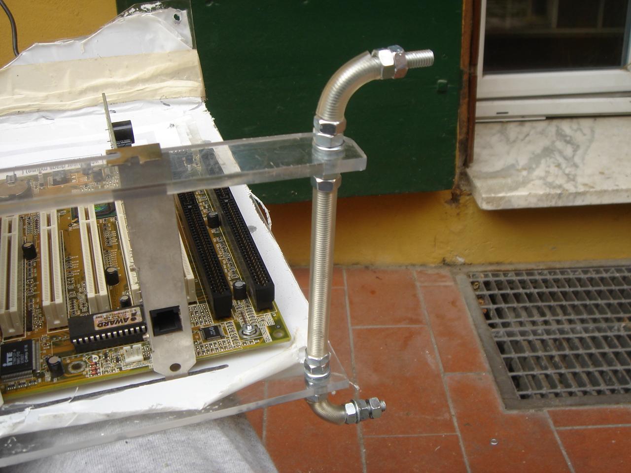
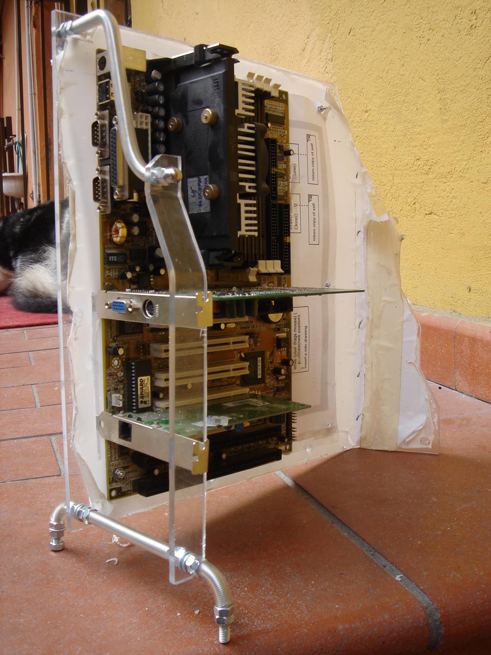
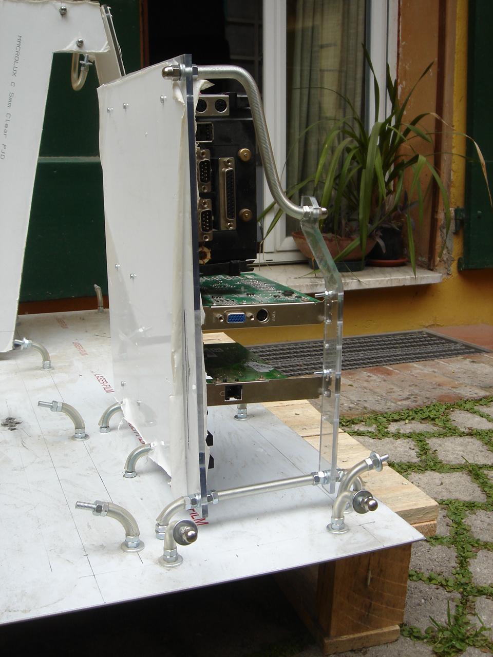
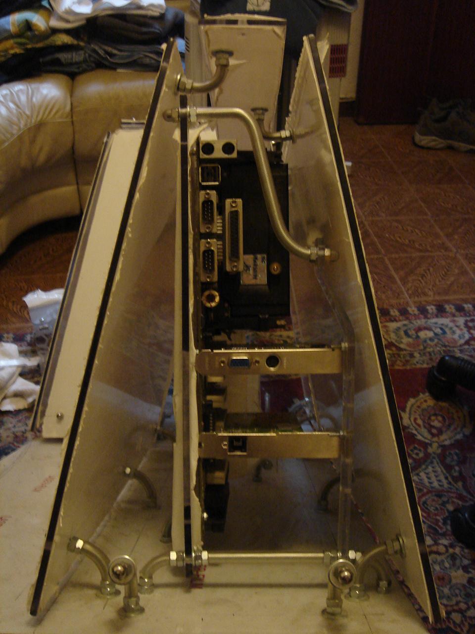
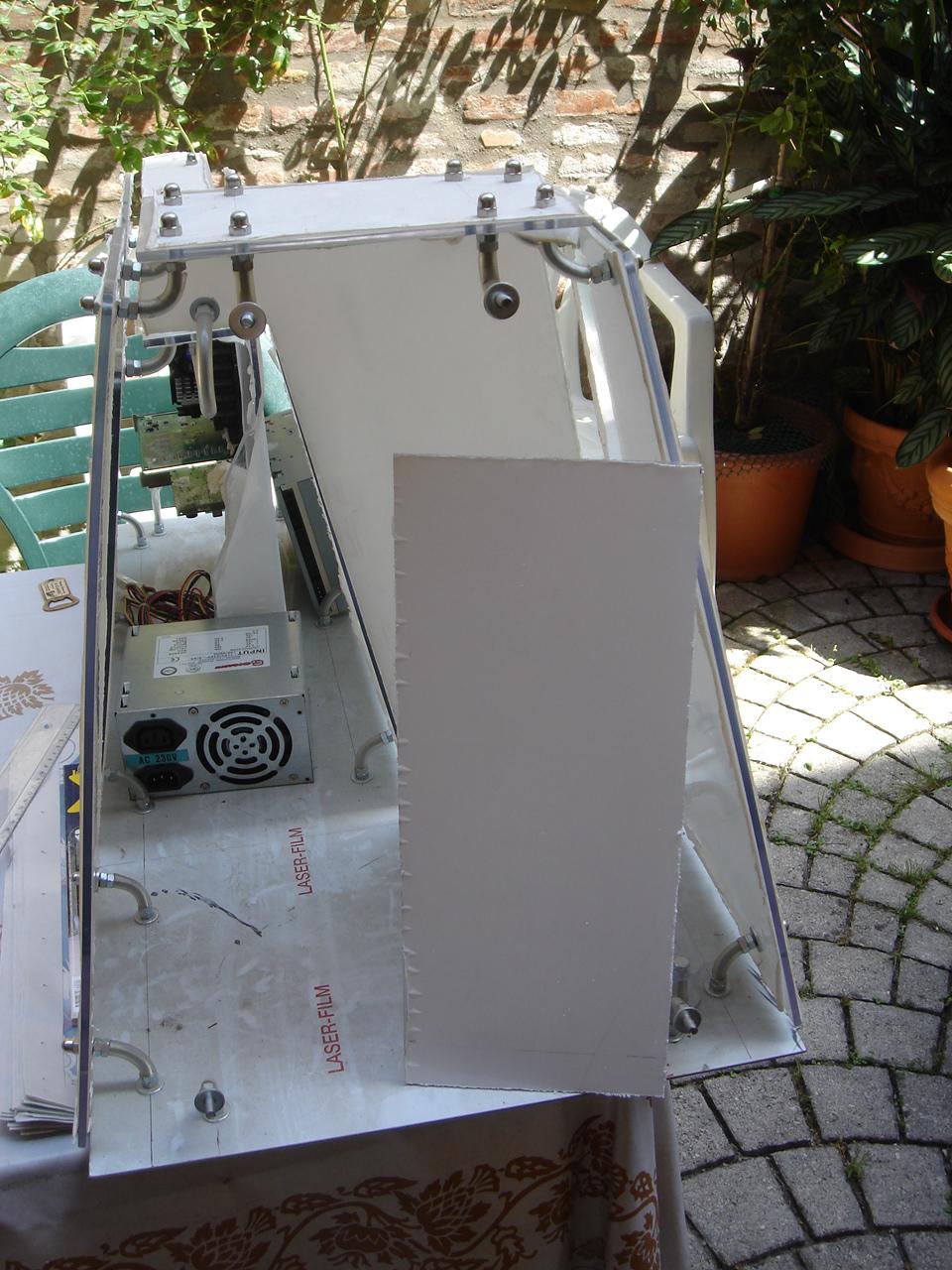
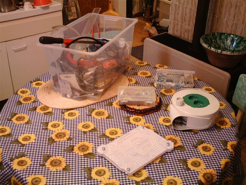
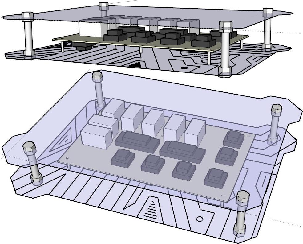
mounting the circuit chassis in the case
I bought another titanium drill tip after damaging my old one, then I mounted the circuit encasing in the case:
and here it is placed in its position:
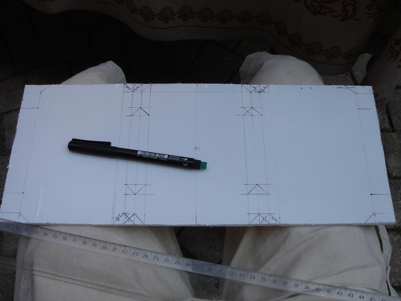
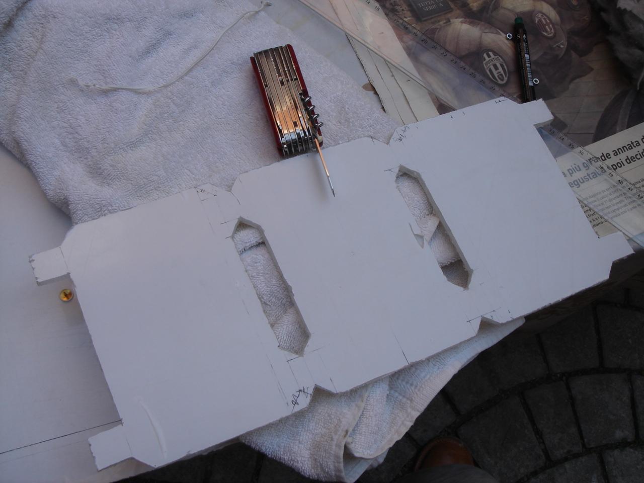
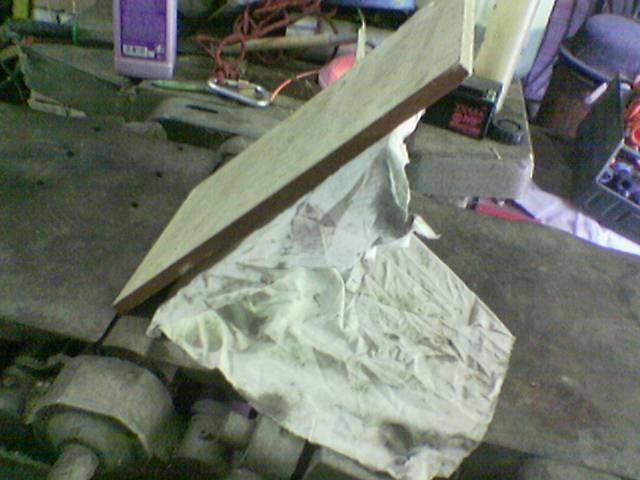
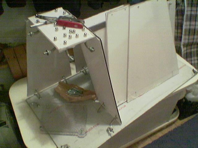
starting the motherboard structure
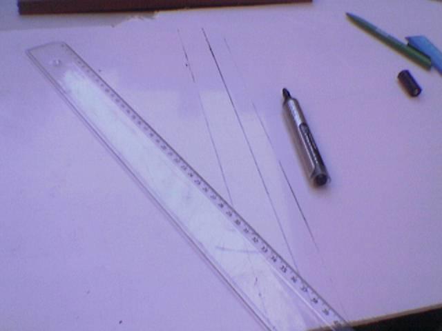
After some measures I traced the first lines for the support of the motherboard:
in this photo I did a test to see how much space to leave on the panel to fold it:
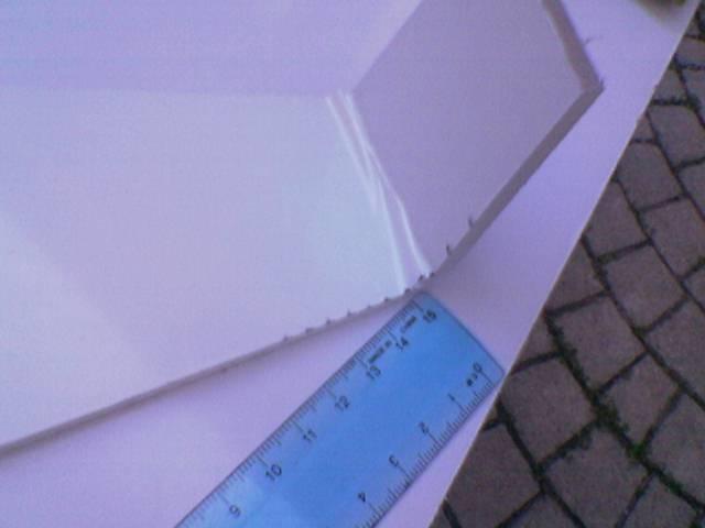
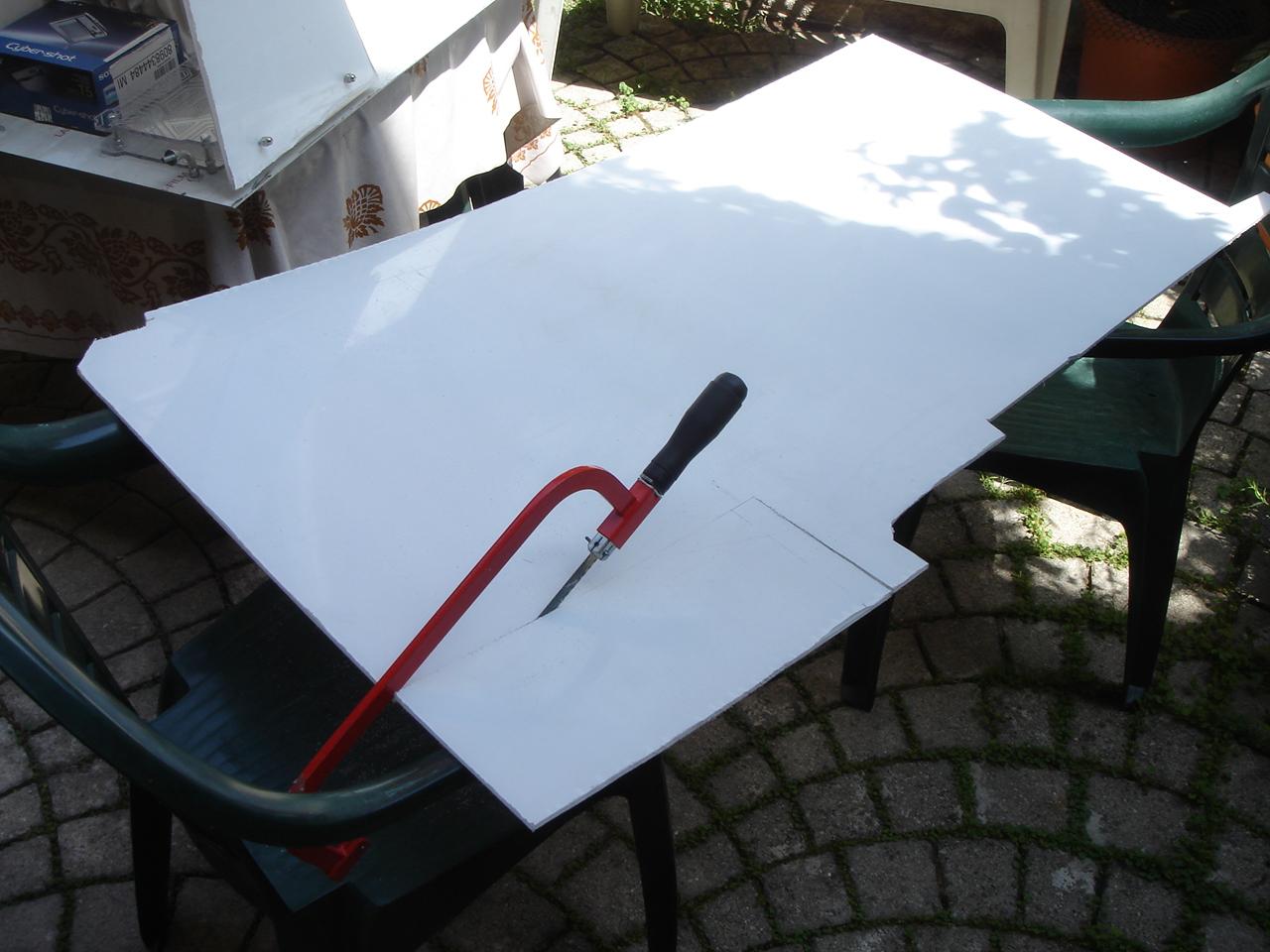
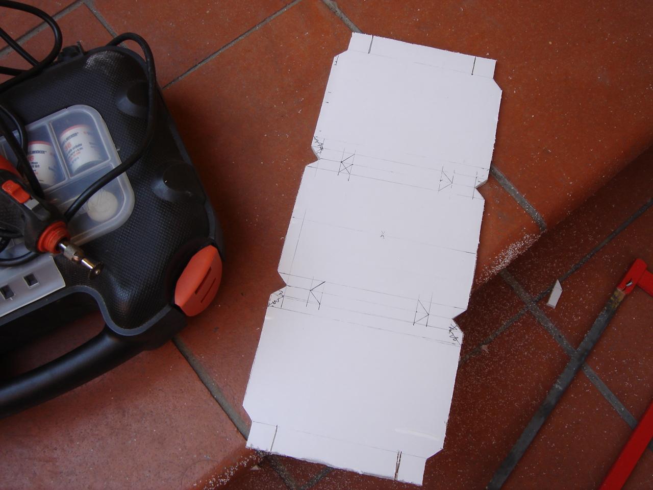
Taken all the appropriate measures I started to cut the panel:
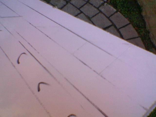
The raw panel cut:
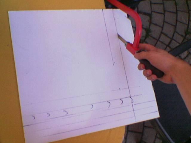
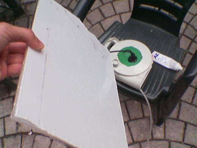
I begin to draw the lines of the left edge (some are oblique to 60 degrees):
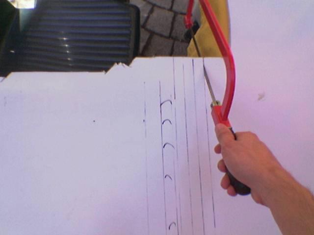
I start to cut them…

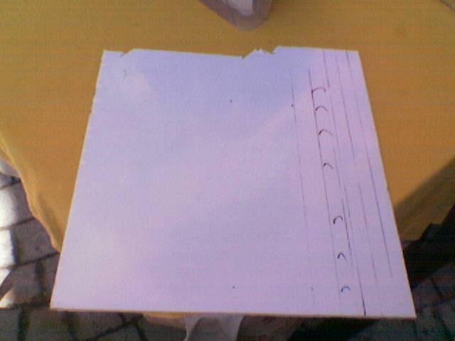
The panel cut:
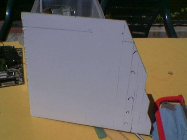
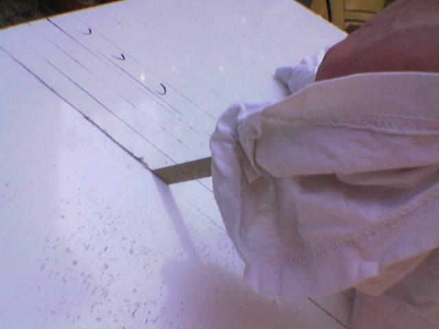
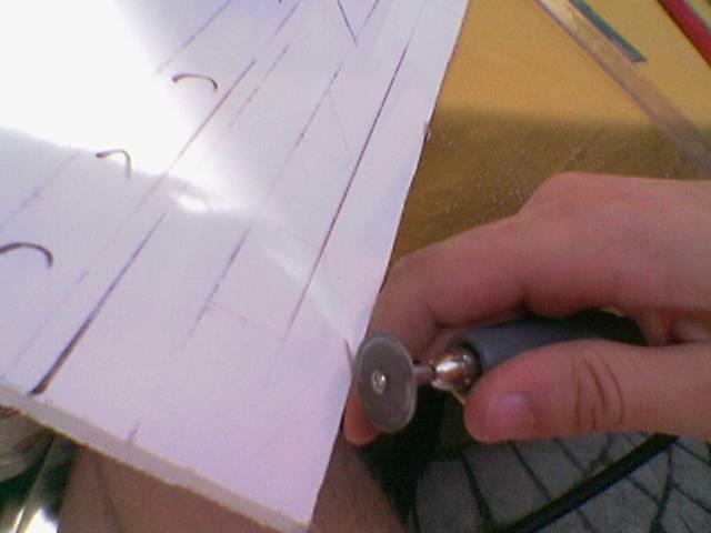
Then I polished the edges:
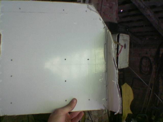
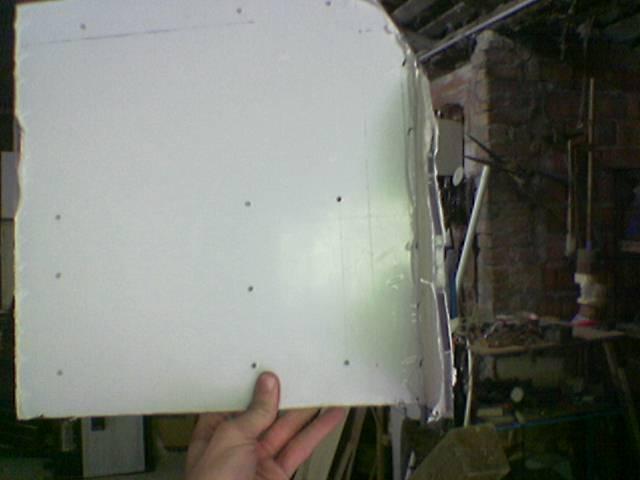
I mark the position of the holes for the motherboard (both atx and microatx)
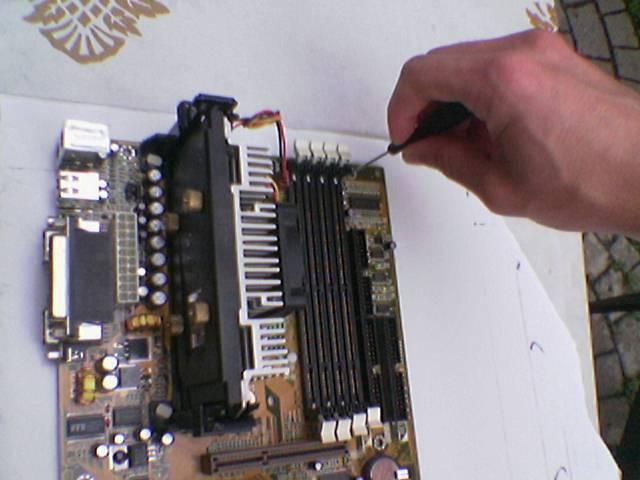
The position of all the holes:
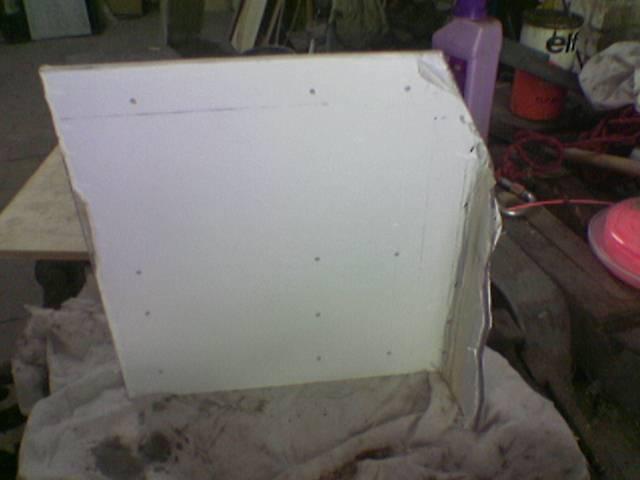
I begin to drill the holes:
Done:
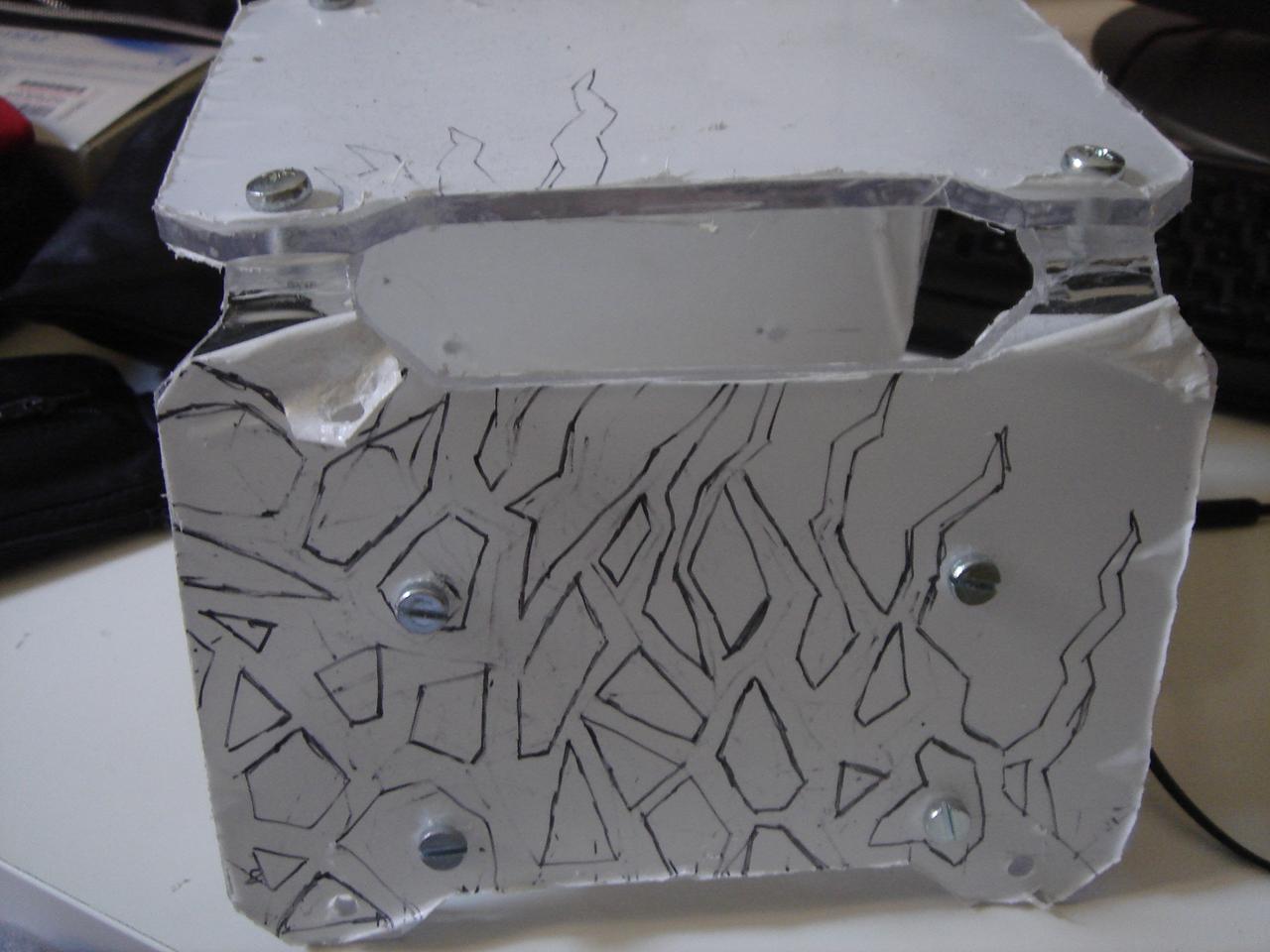
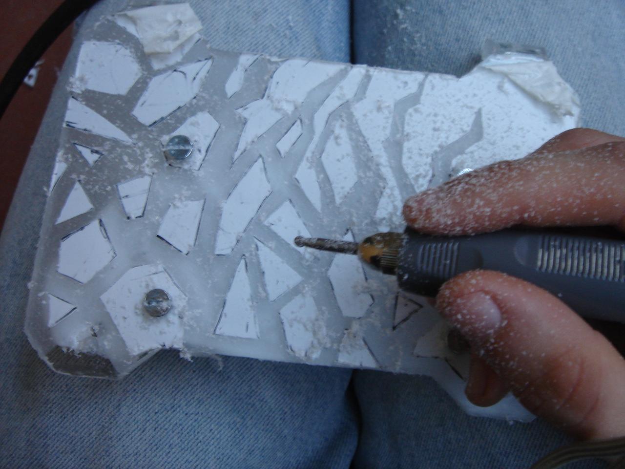
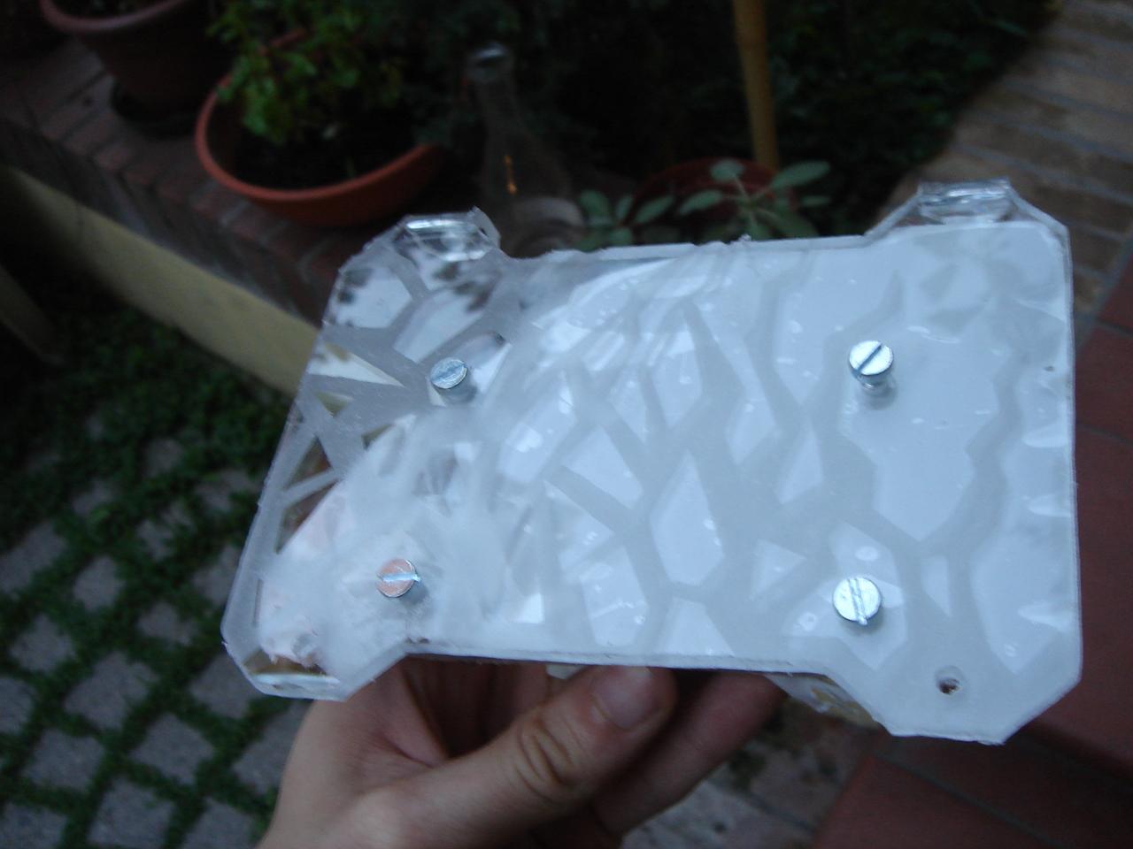
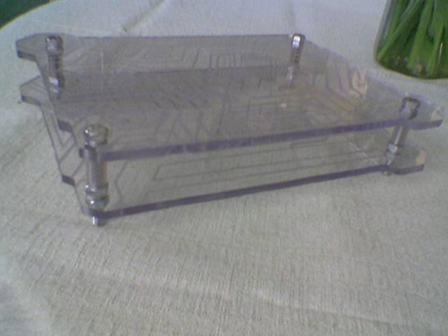
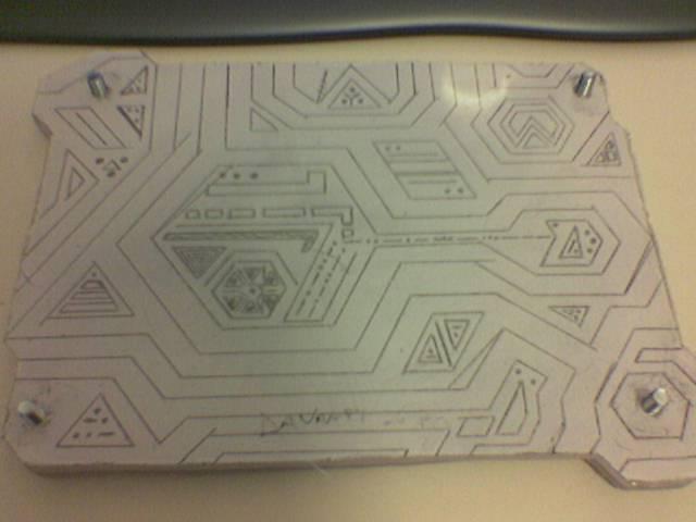
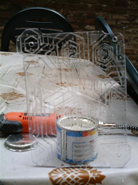
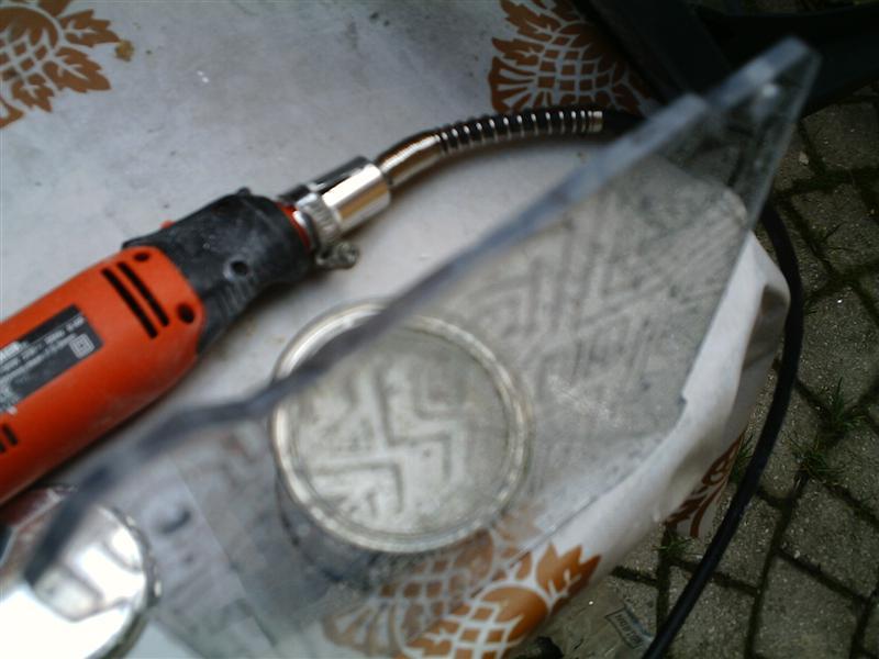
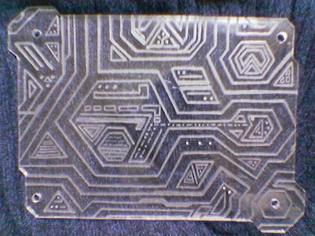
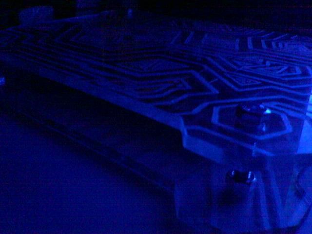
engraving the sensor circuit chassis
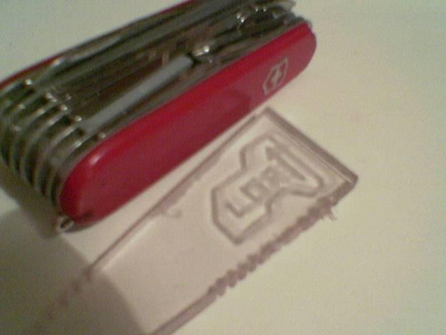
I did a test with a rounded-tip engraving tool of the dremel.
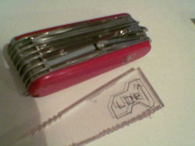
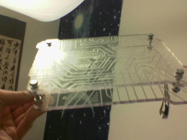
The drawing (the knife is for compare the size):
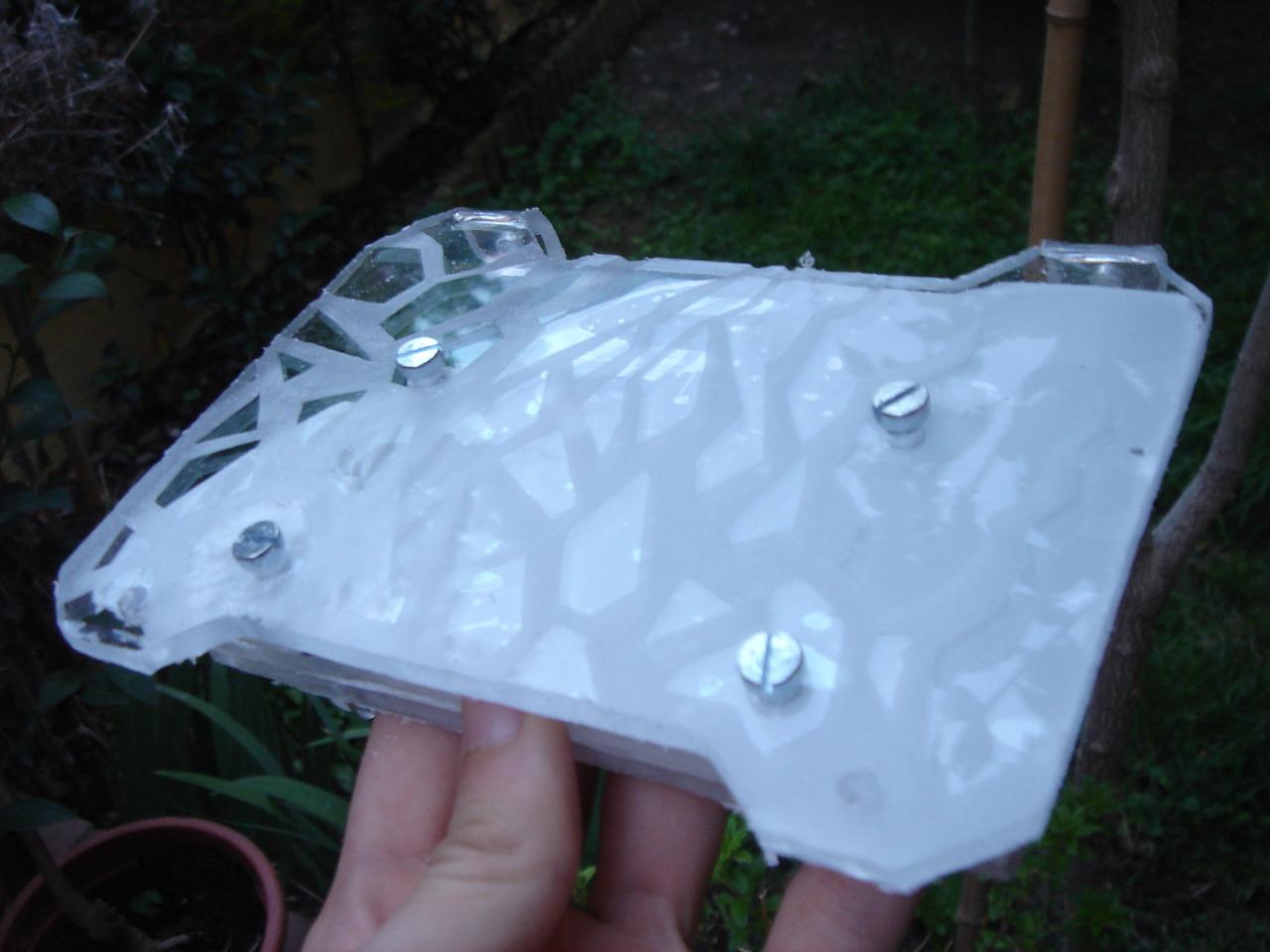
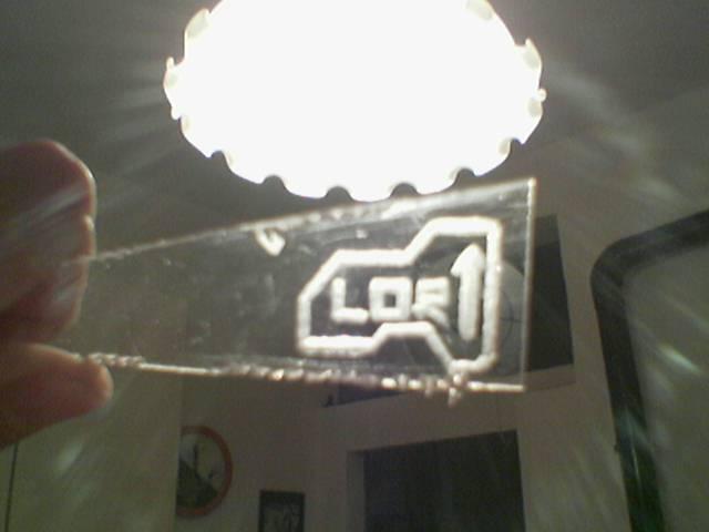
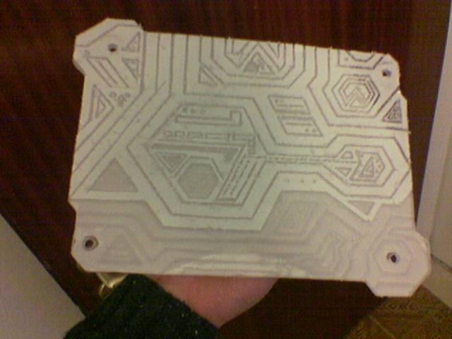
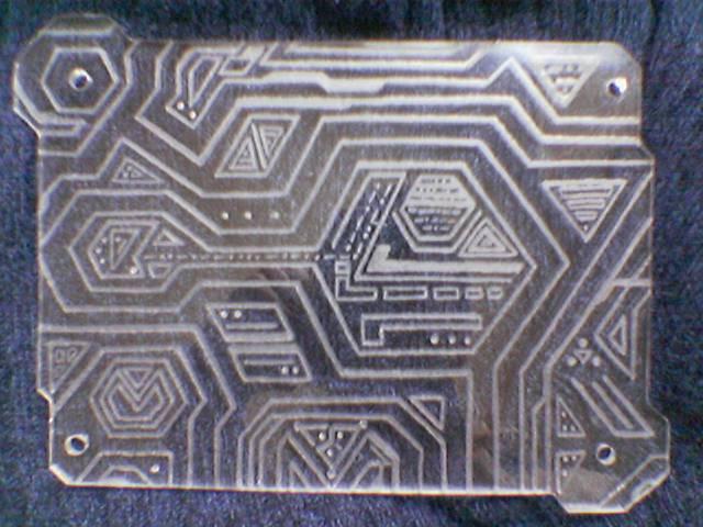
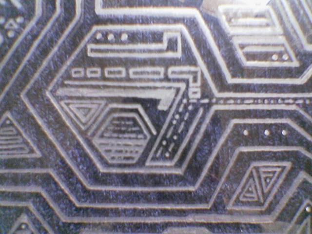
The engraving:
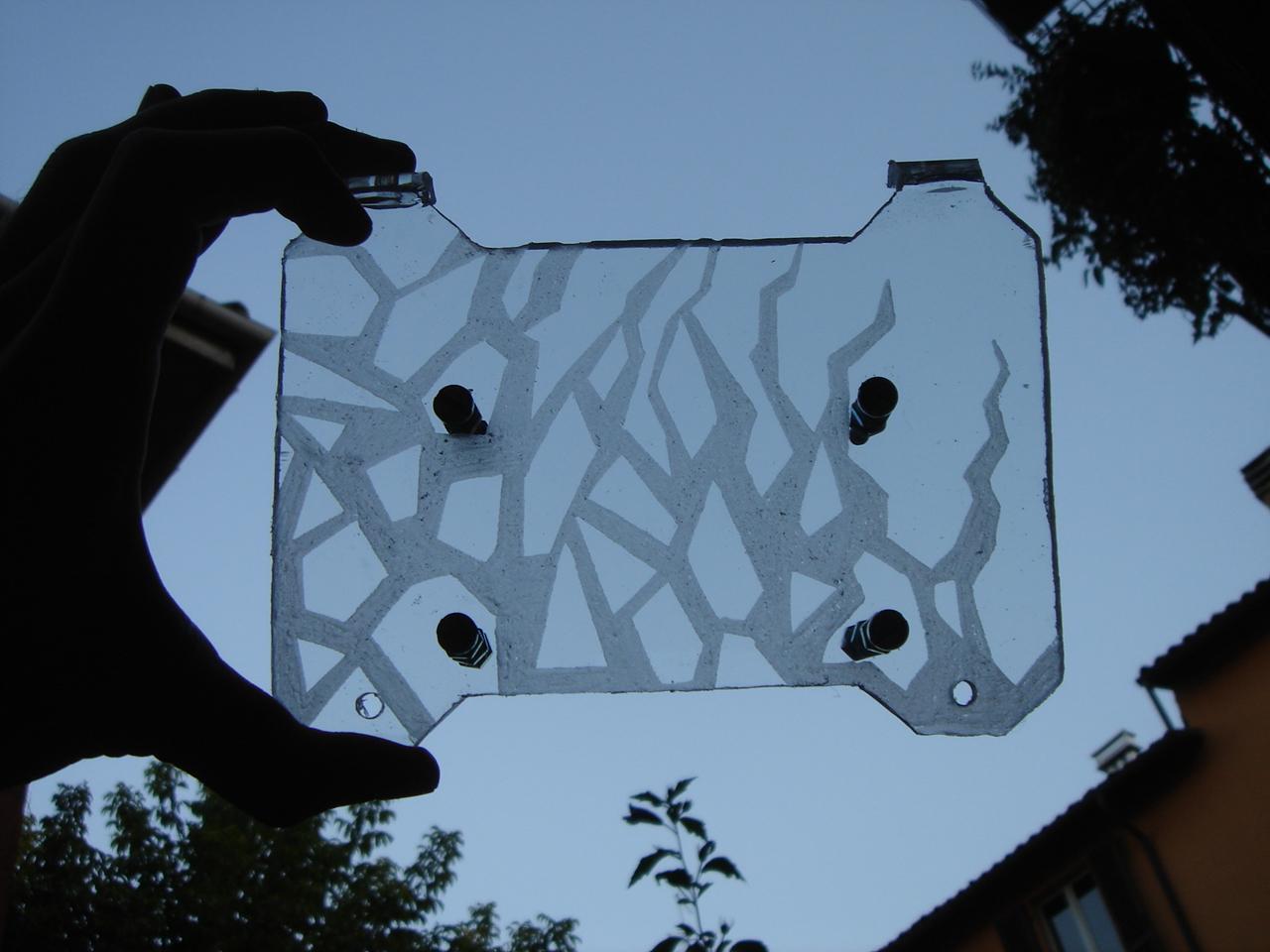
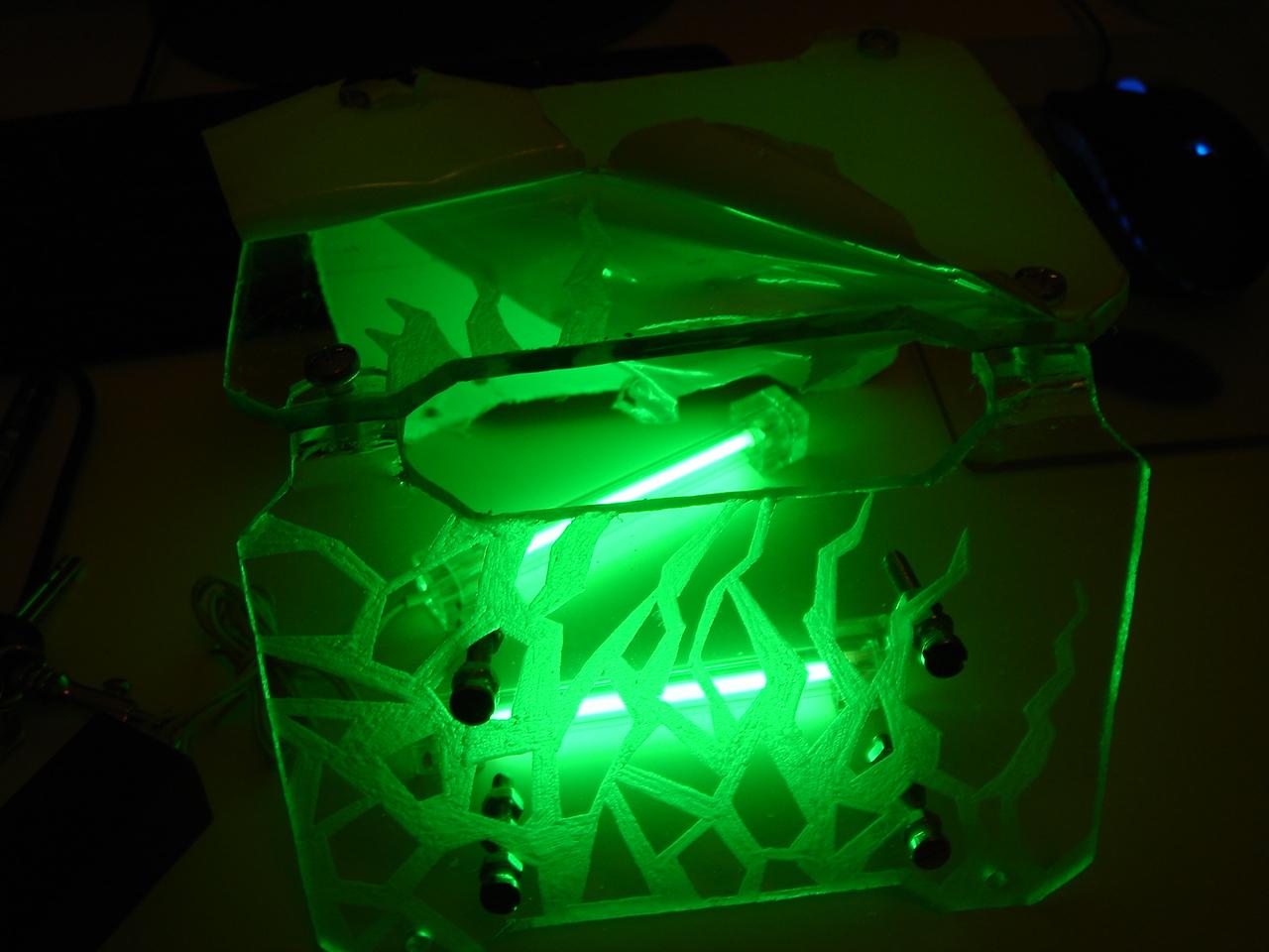
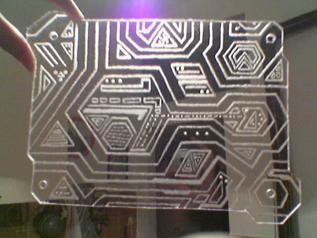
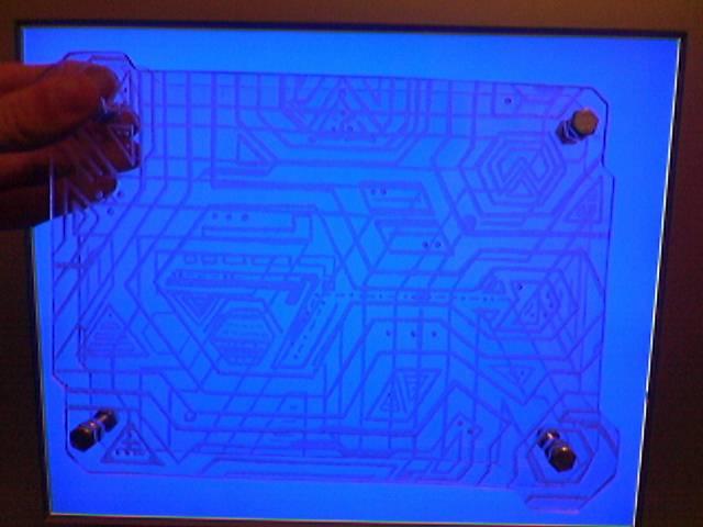
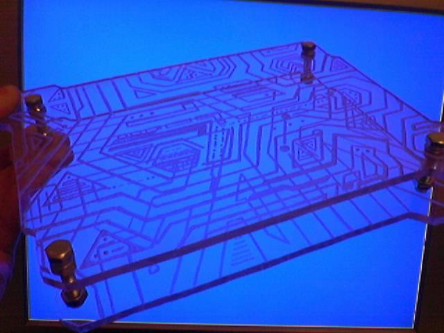
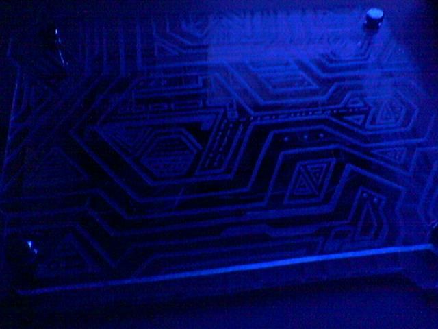
The illuminated engraving:
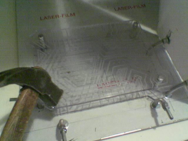
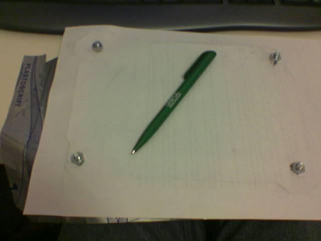
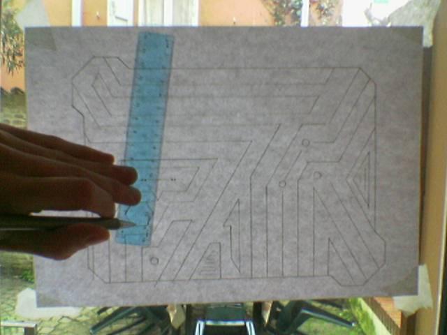
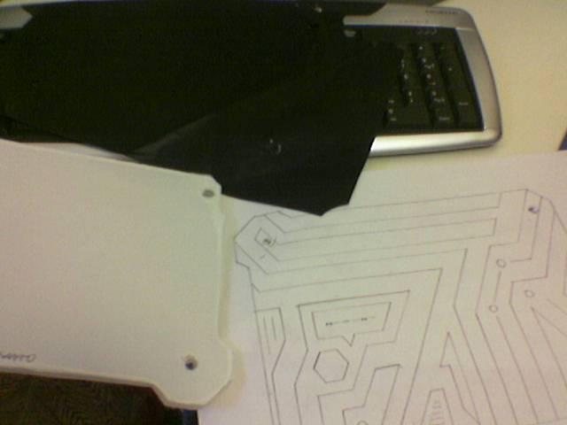
I draw on paper the engraving (under the paper there is a carbon copy sheet):
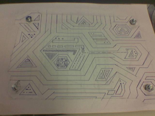
I made the drawing… (trying to follow the style of some environments of Tron 2.0)
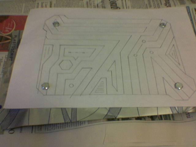
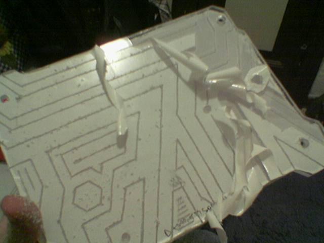
The drawing imprinted on the protective film:
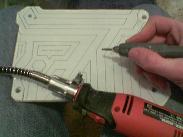
The first pass of the engraving (this method require two steps: a first pass with the protective film, and a second pass without the film to refine the engraving):
I remove the remaining film:
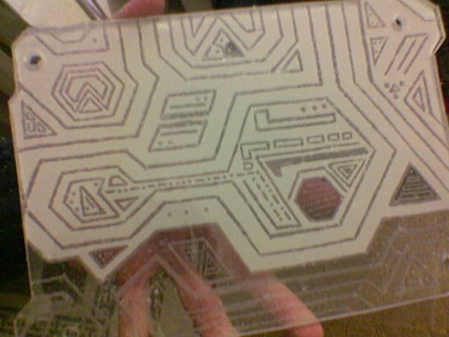
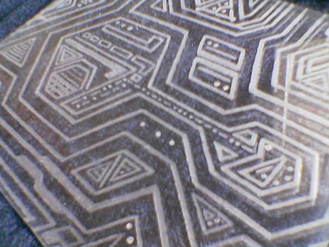
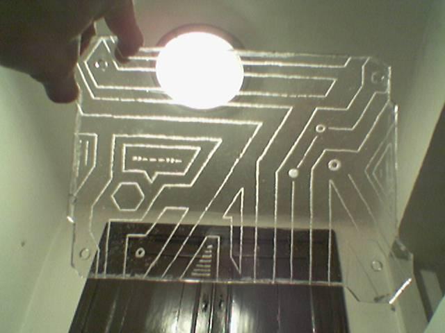
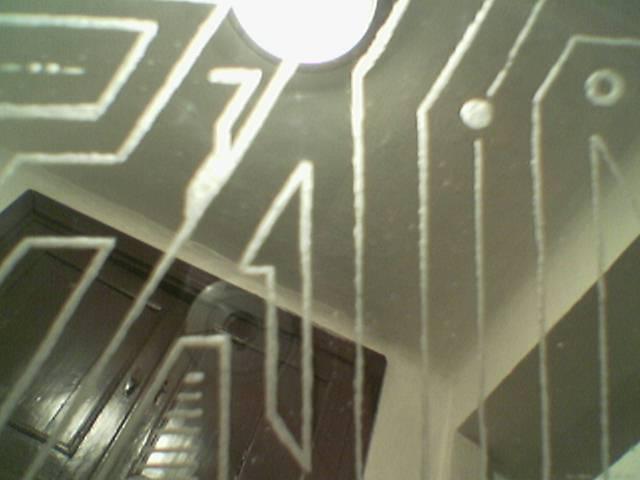
The engraving enlighted (this is only the first pass, so the engraving is a bit raw):
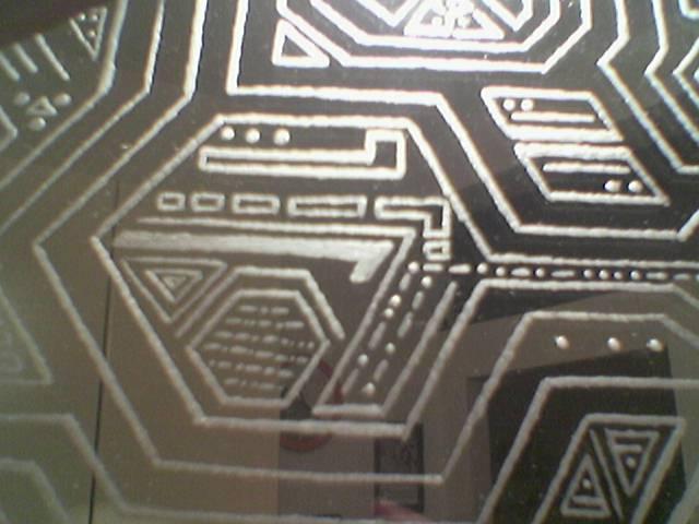
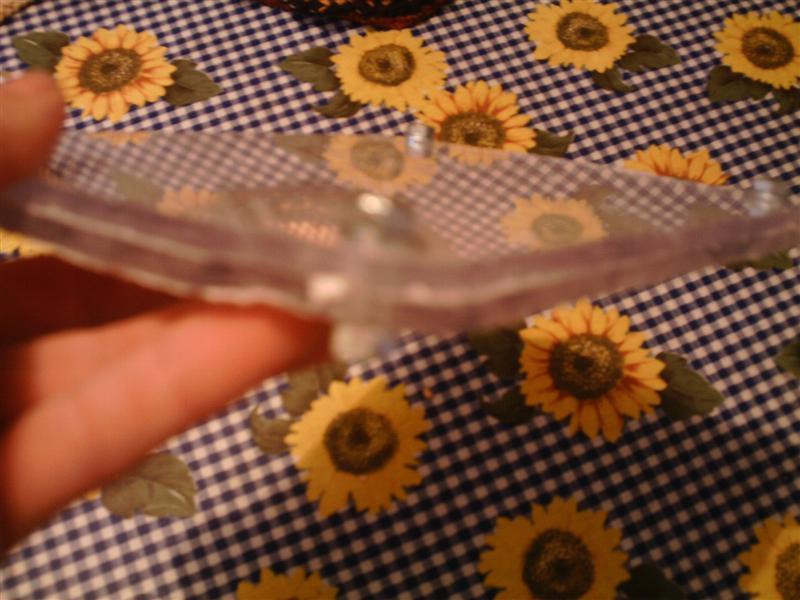
I polished the edges of the engraved panel:
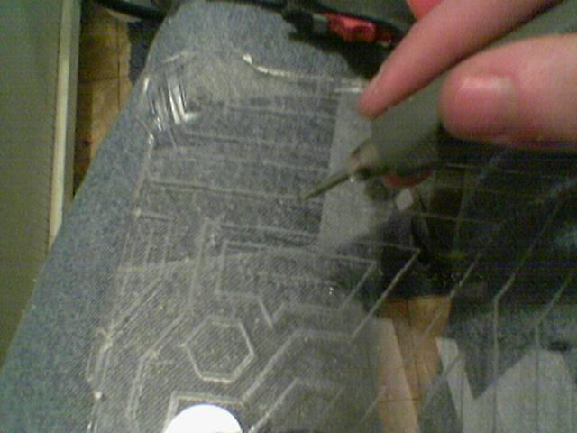
Then I have done the second pass of the engraving, to refine every single groove:
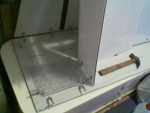
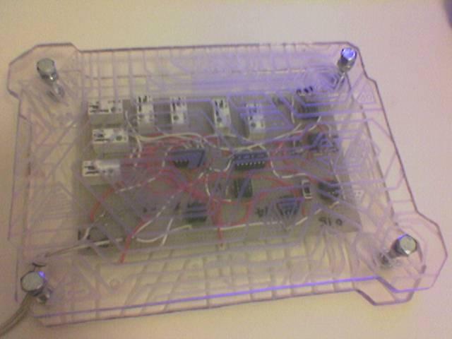
I made the drawing for the lower panel of the circuit chassis:
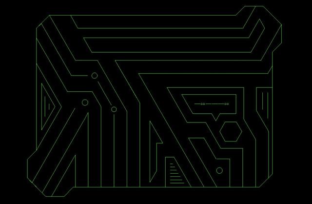
And a preview of this drawing on the structure:
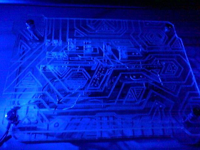
Engraving the lower panel:
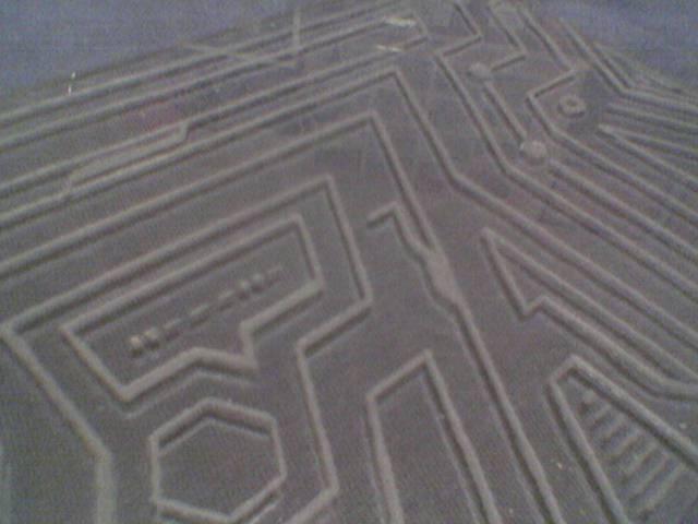
Finished the first pass:
Then i proceed with the second pass:
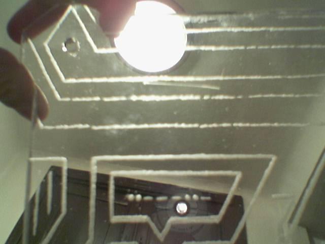
A comparison between raw grooves of the first pass (top in 1st photo, right in 2nd one) and refined grooves of the second pass (bottom in 1st photo, left in 2nd one):
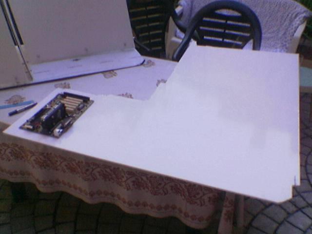
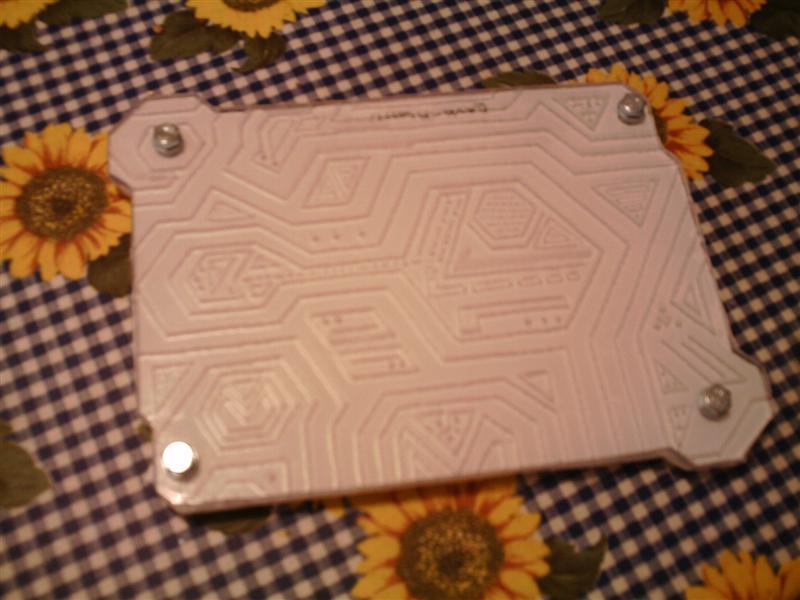
The finished panel:
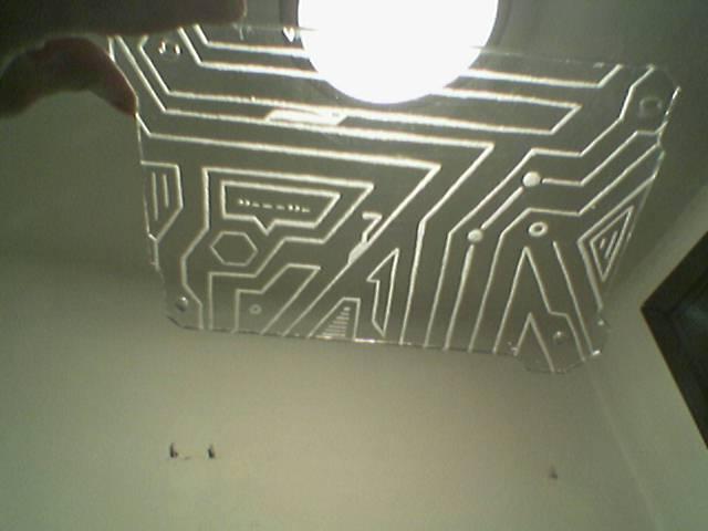

A mounting test:
And a test with the circuit inside:
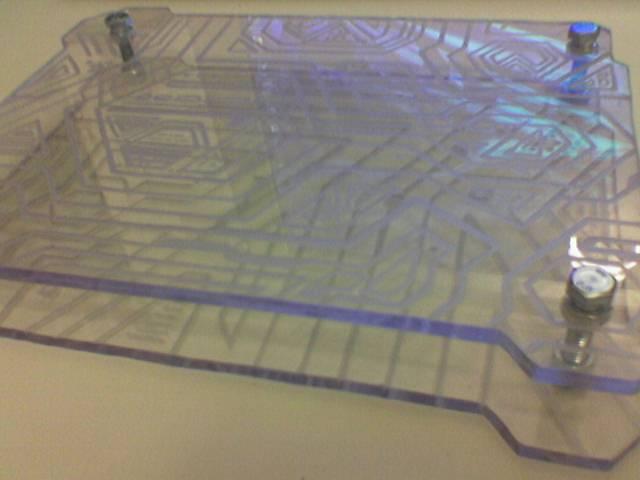
Some lighting tests:
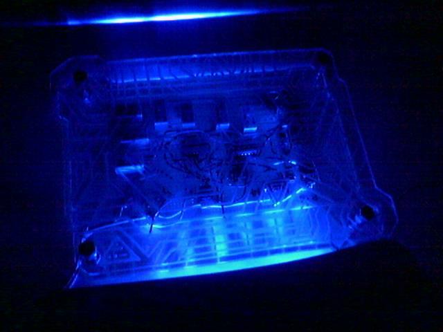
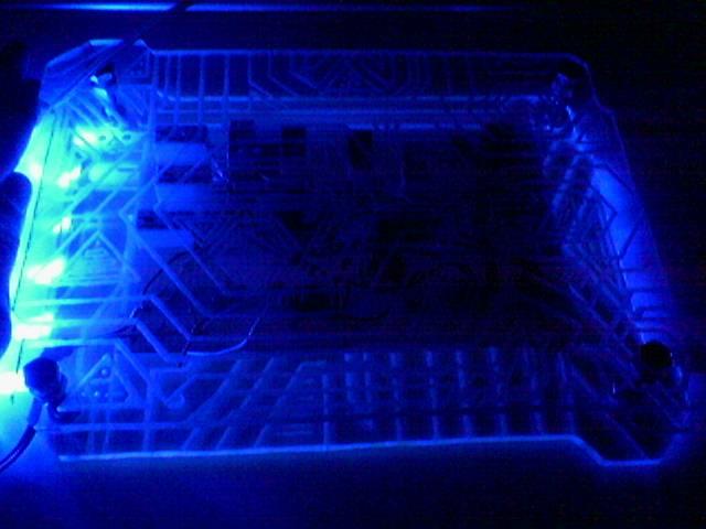
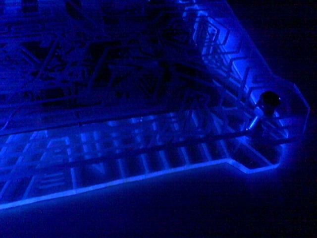
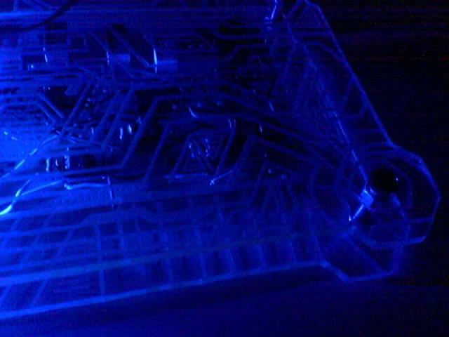
Can you start to see some Tron 2.0 atmosphere? 😀