Category Archives: Lonherz Kernel

painting and mounting the case feet

I realized that I forgot one thing: the case feet!

I previously cutted and painted in grey 8 wood discs:

To make a “metal” effect, I sprayed a little quantity of white paint. It was just the quantity to obtain little white dots on the grey background, so these drops seems like light reflections, as in a raw metal surface.
This is the effect:

This is the sequence:

First the grey backround:

Then the quick pass with white spray, to form the little white dots:

I glue the felt pads:

And this is the result:

photos of the assembled computer

Now I can finally put the case outside for some photos:

but there’s one thing missing: a transparent “Lonherz Kernel” sticker:
[Note from the future: I didn’t like that sticker, so I removed it after a while]

AND NOW A LOT OF PICS OF THE ASSEMBLED COMPUTER! 😀

Powered off, without flash:

Powered off, with flash:

And powered on at the twilight:

mounting the fans

The two fans (speed controlled by one of the touch sensors) are placed over the projector, to generate a flow from the motherboard zone to the left tower:

To mount each of them I used a steel bar and a bolt, to hang them on two roof joints:

The hanging system:

The fans were too big, so I had to cut one of the corners to fit them in place:

And finally these are the fans mounted:

assembling the PC and case lightings

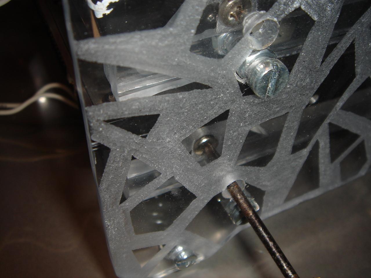
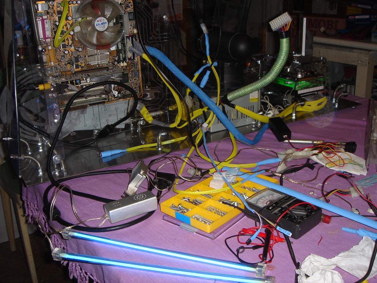
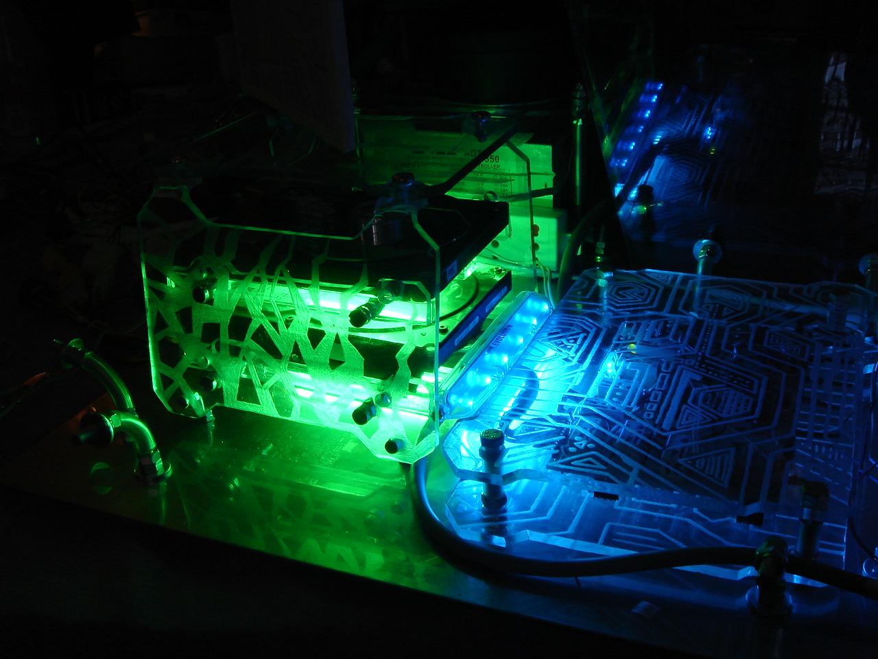
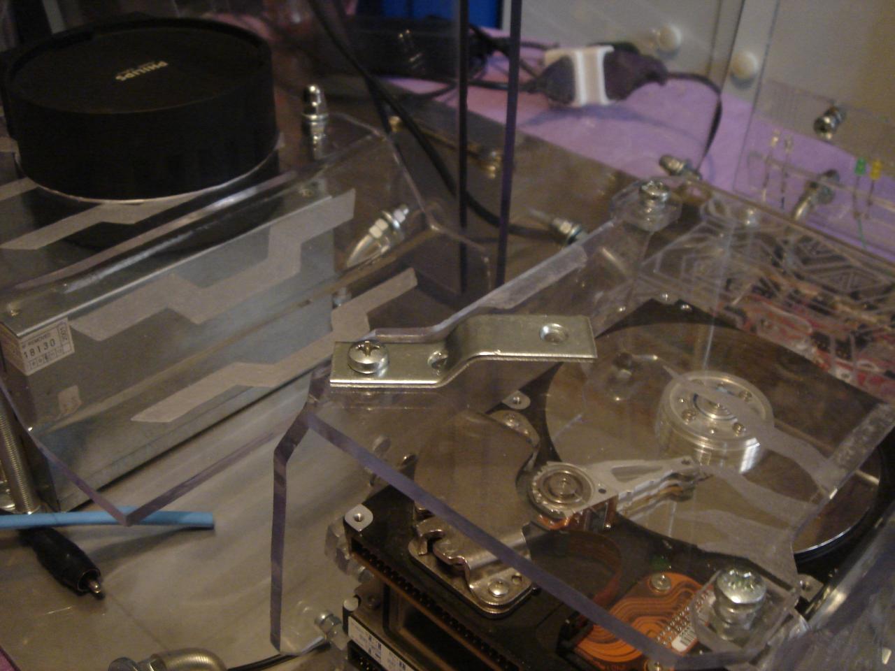
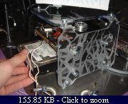
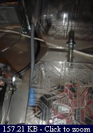
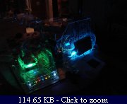
Here I remove the dummy hard disk and I put two green cold cathode lights:

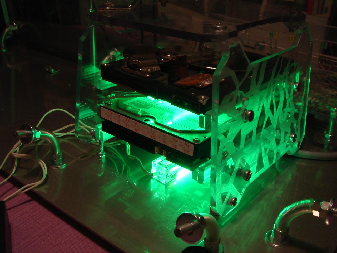
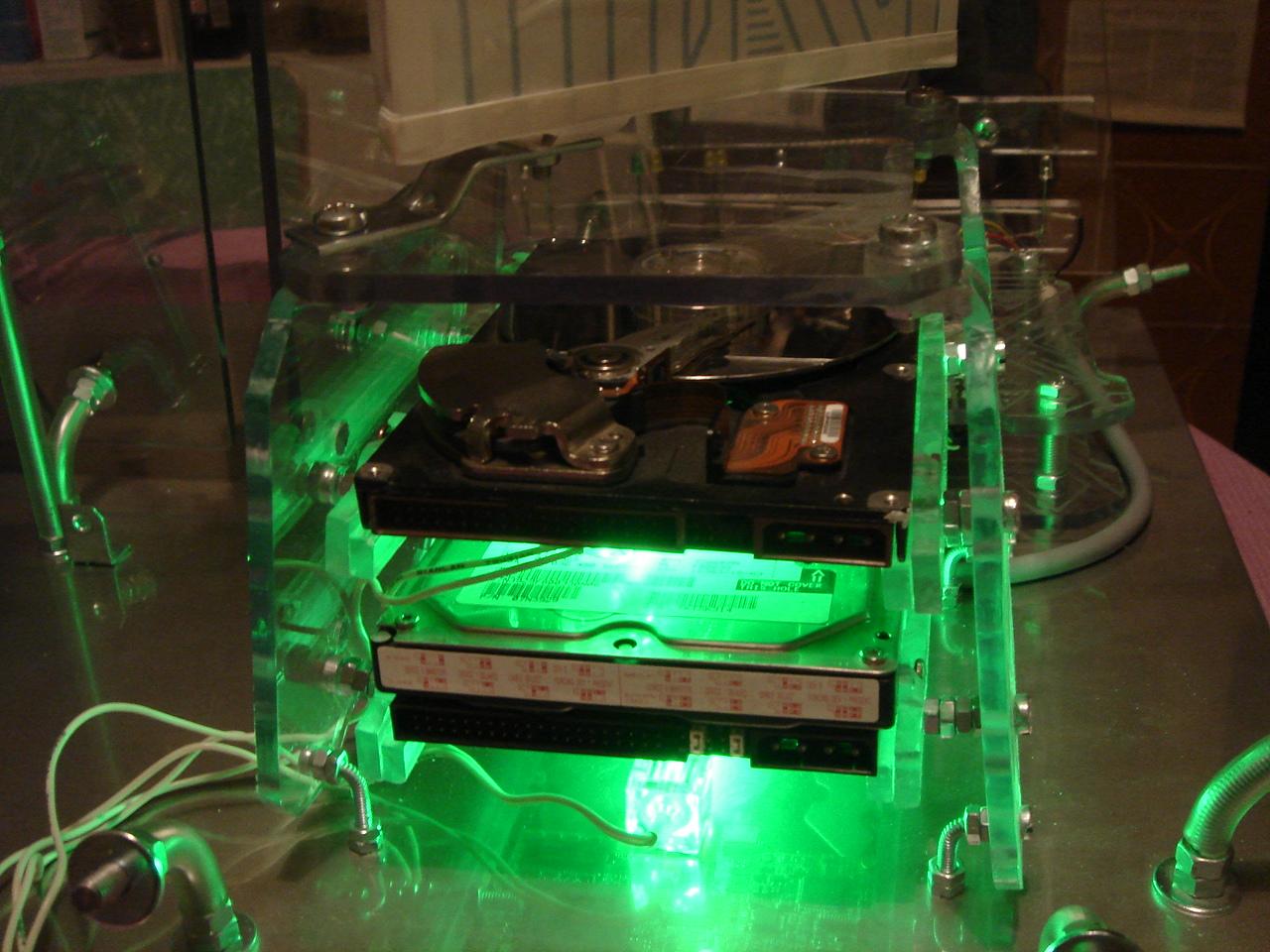
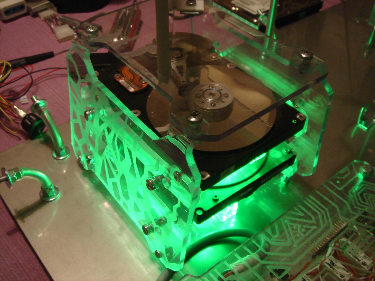
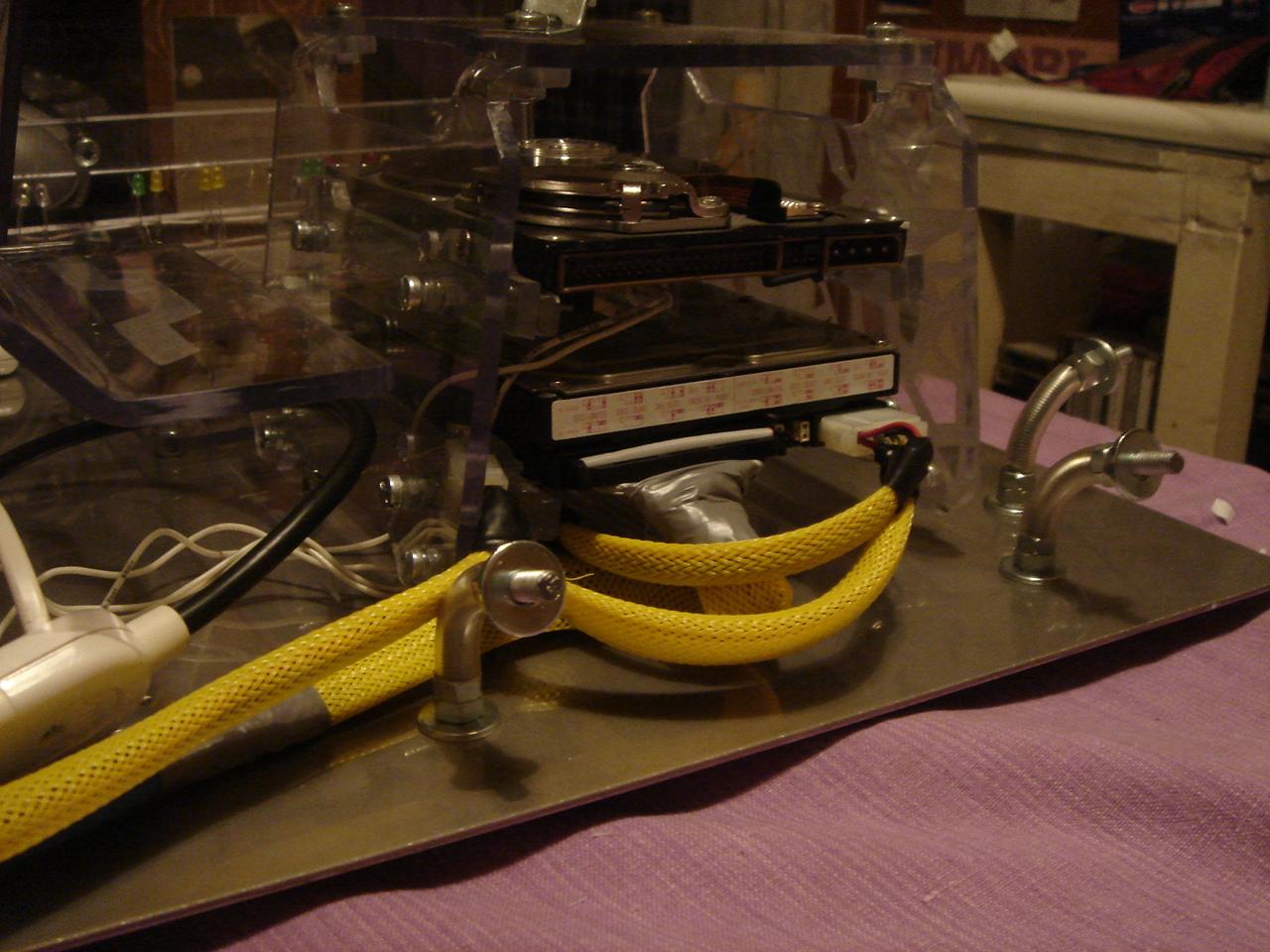
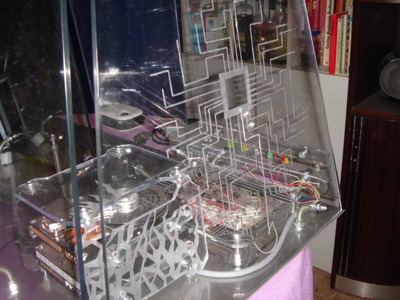
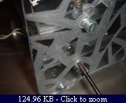
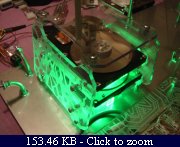
I mount the real hard disk:

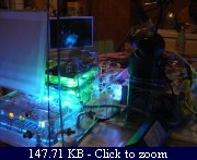
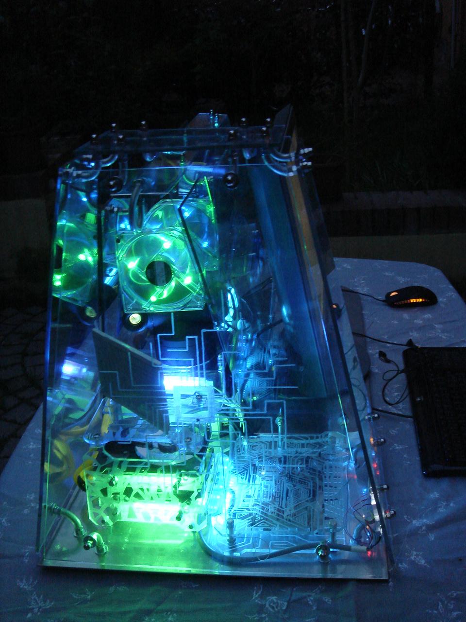
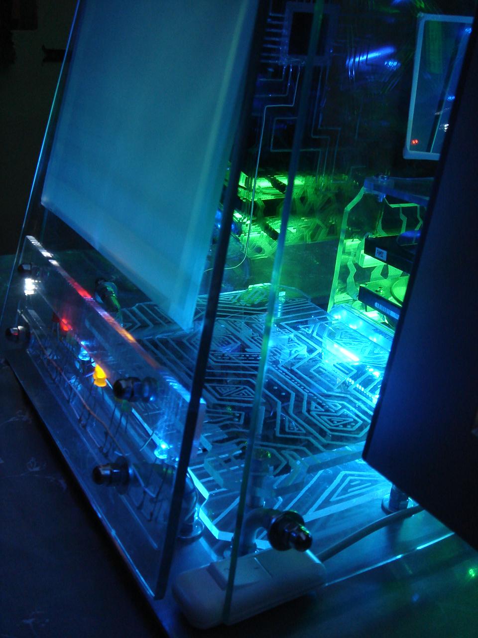
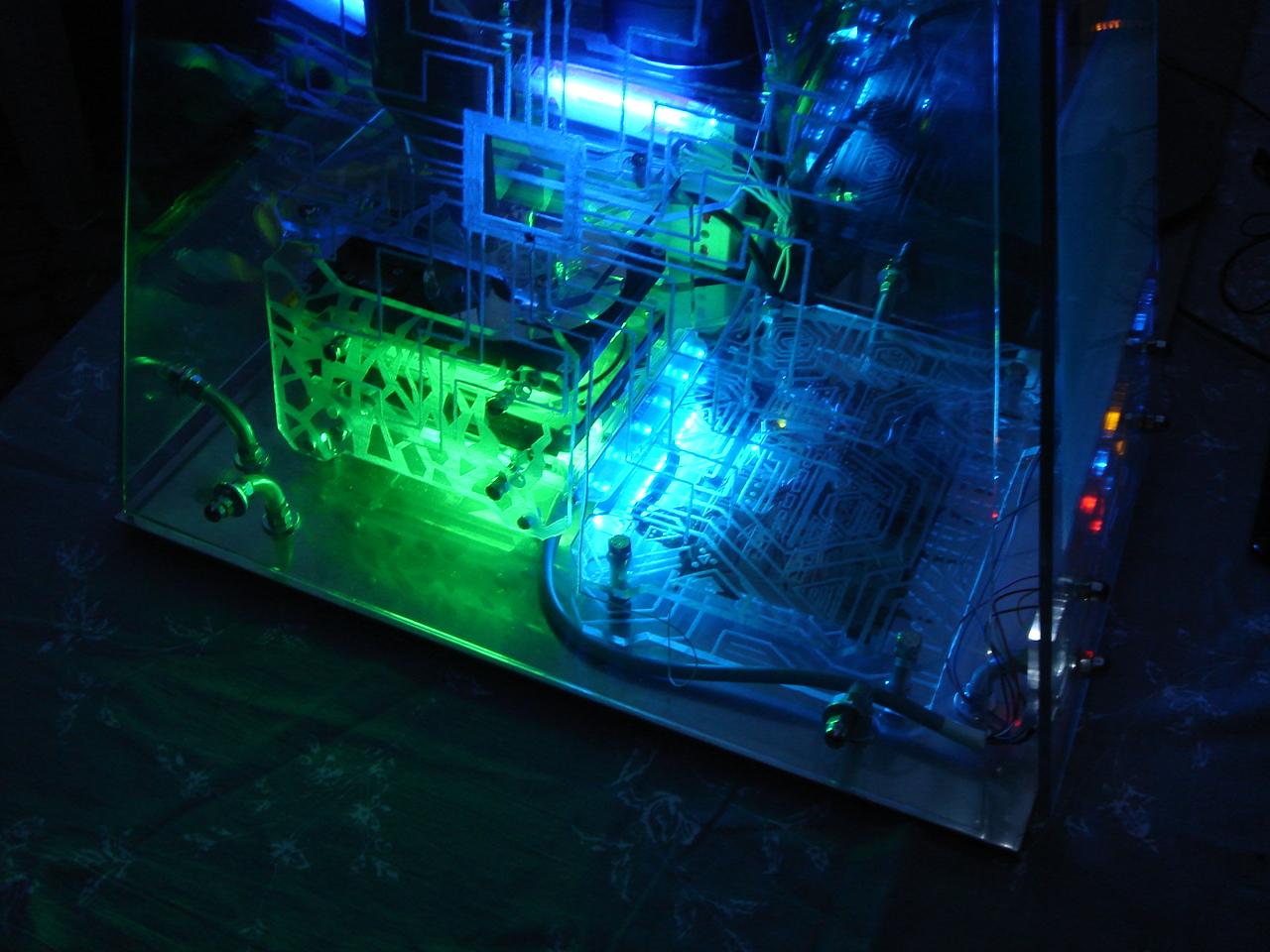
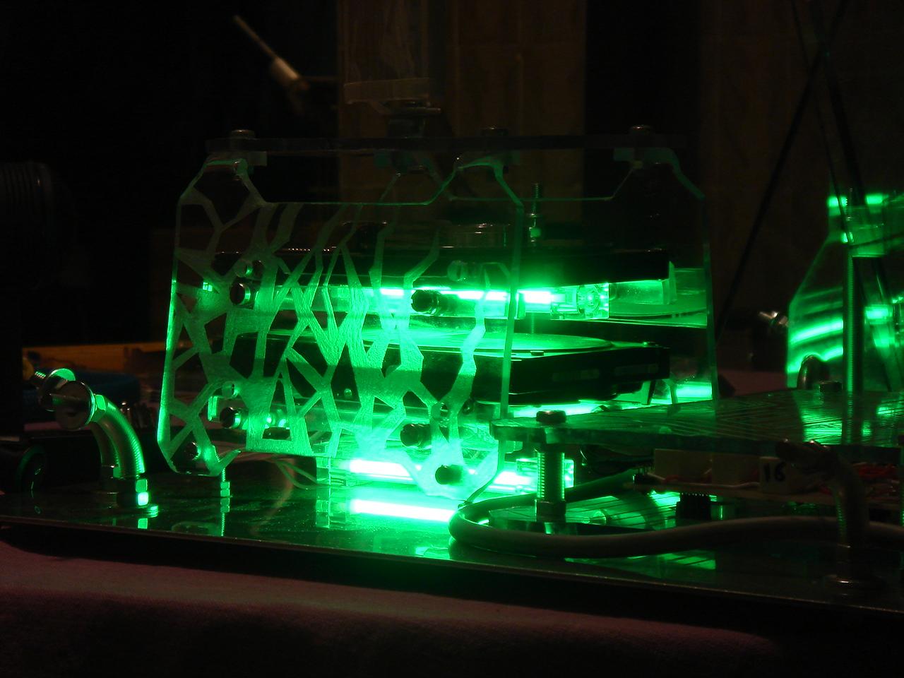
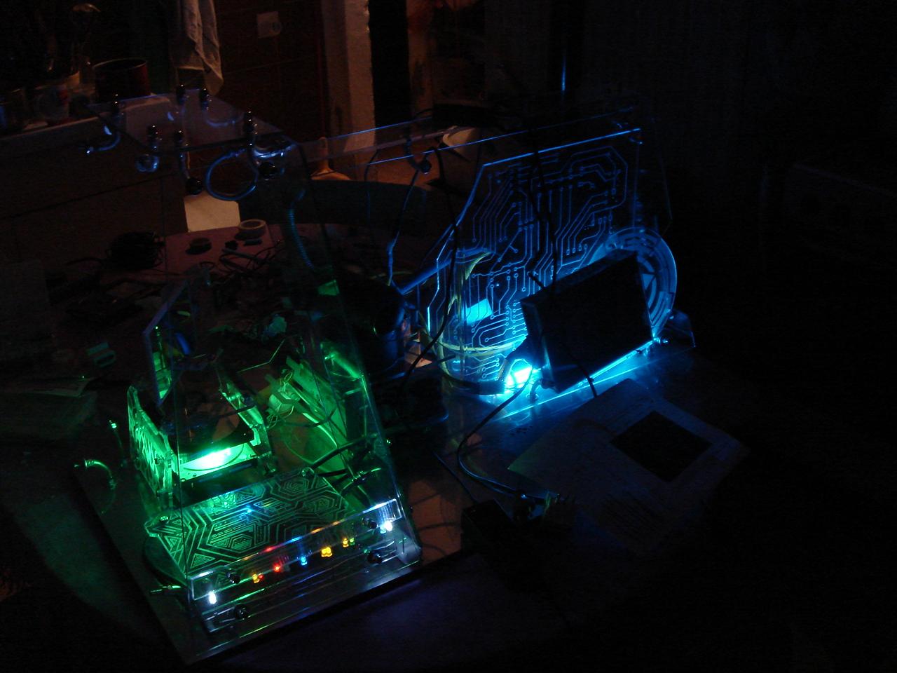
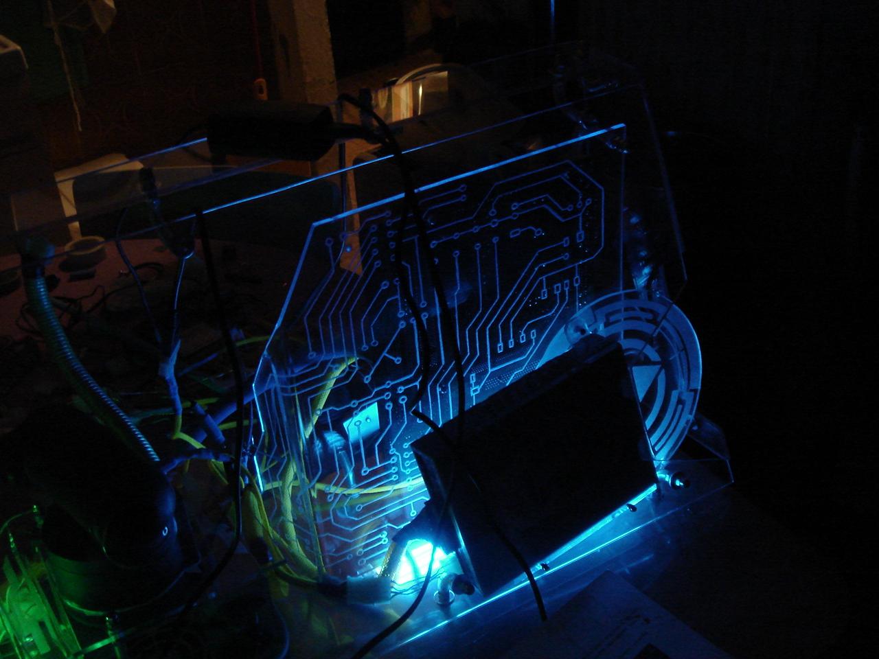
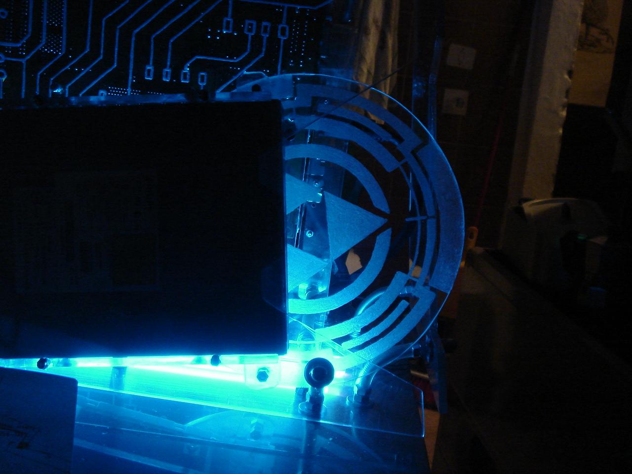
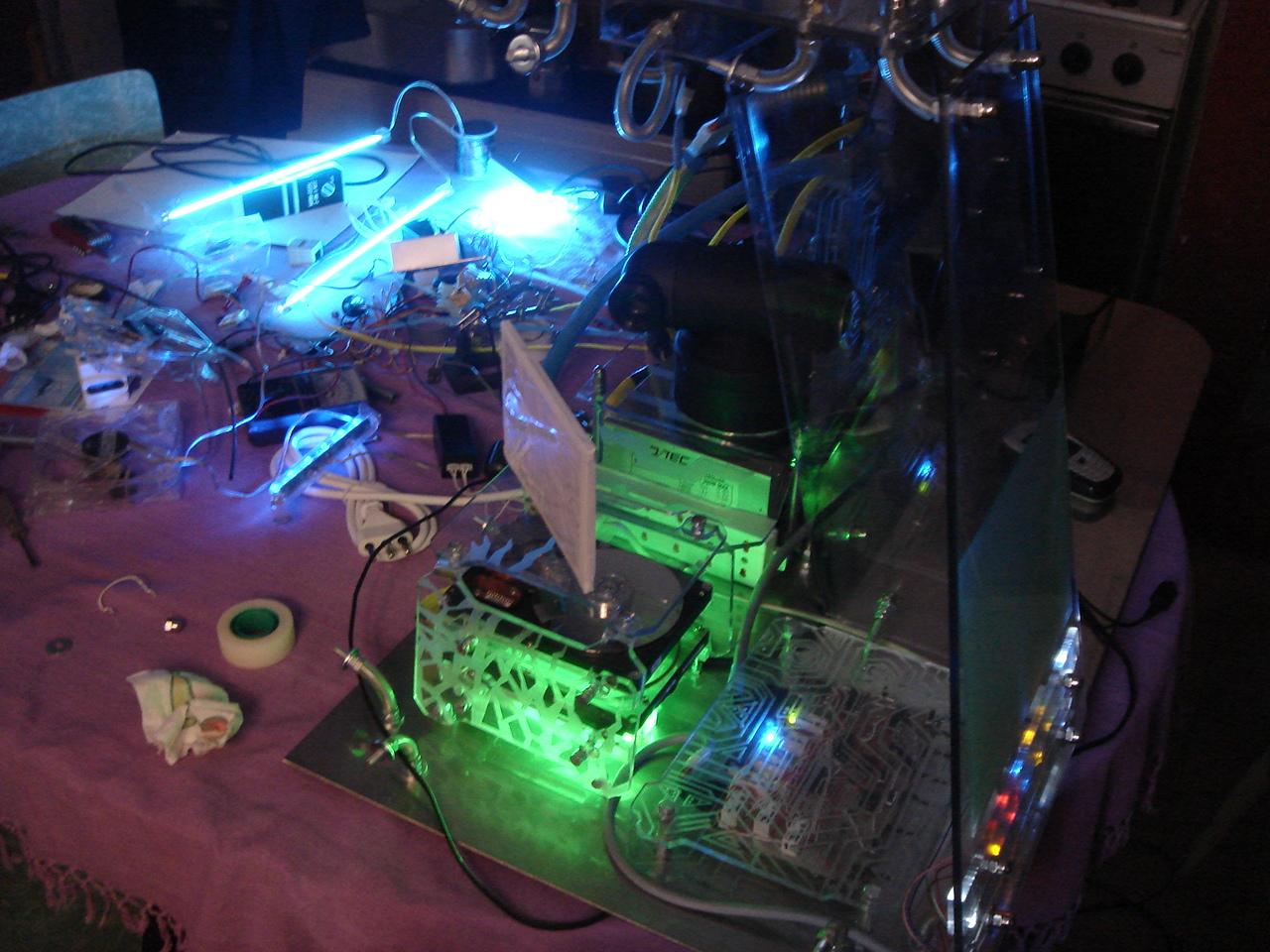
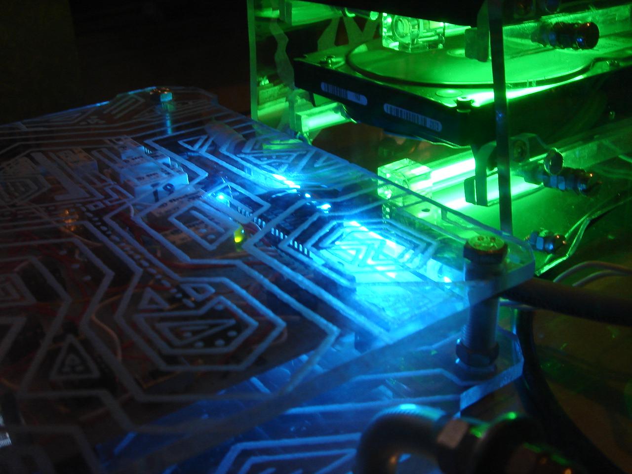
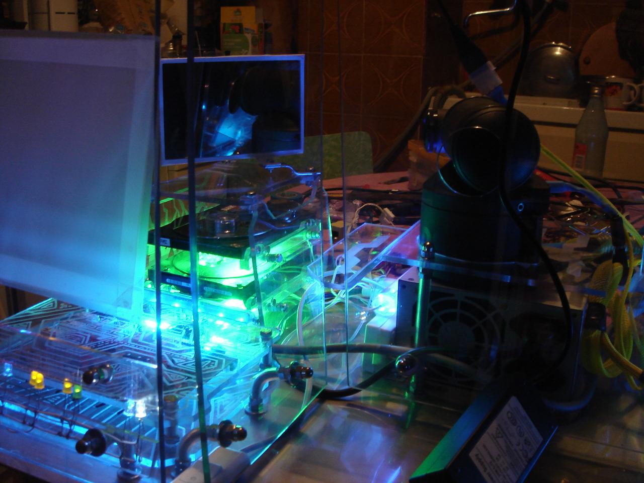
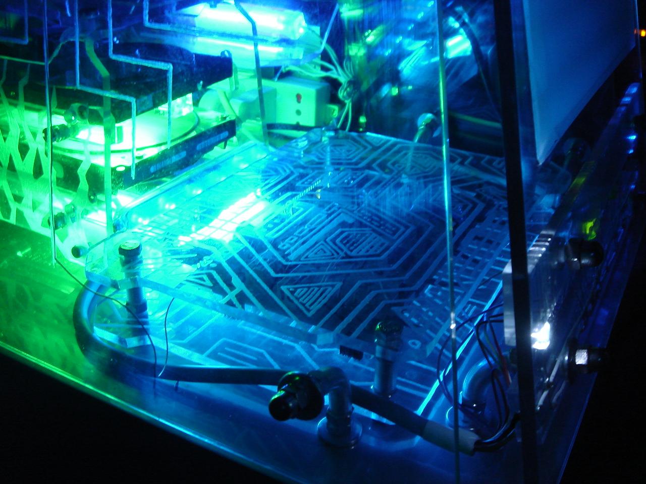
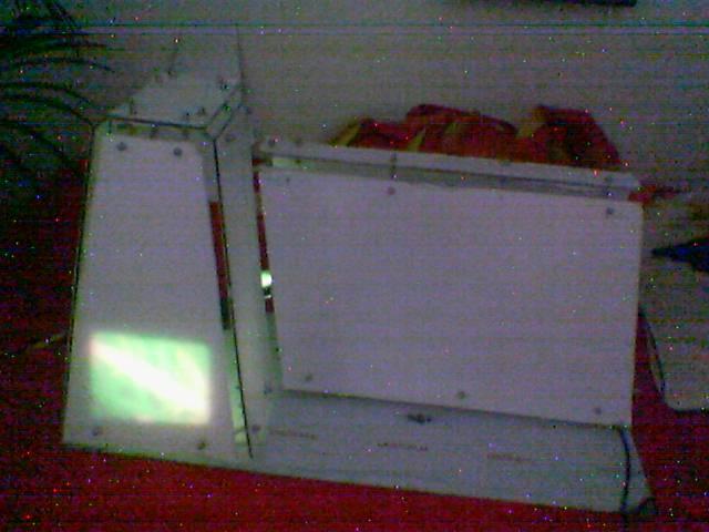
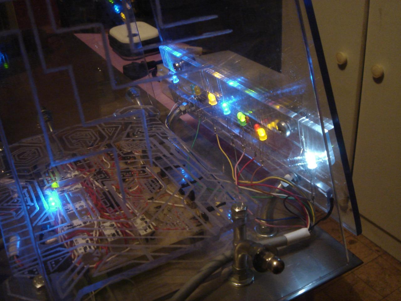
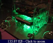
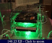
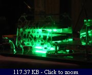
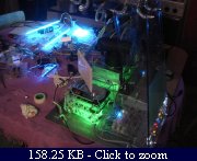
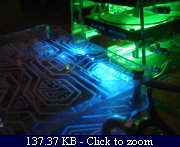
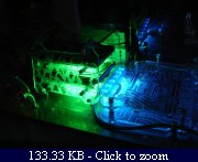
A lighting test of the “infected sector”:

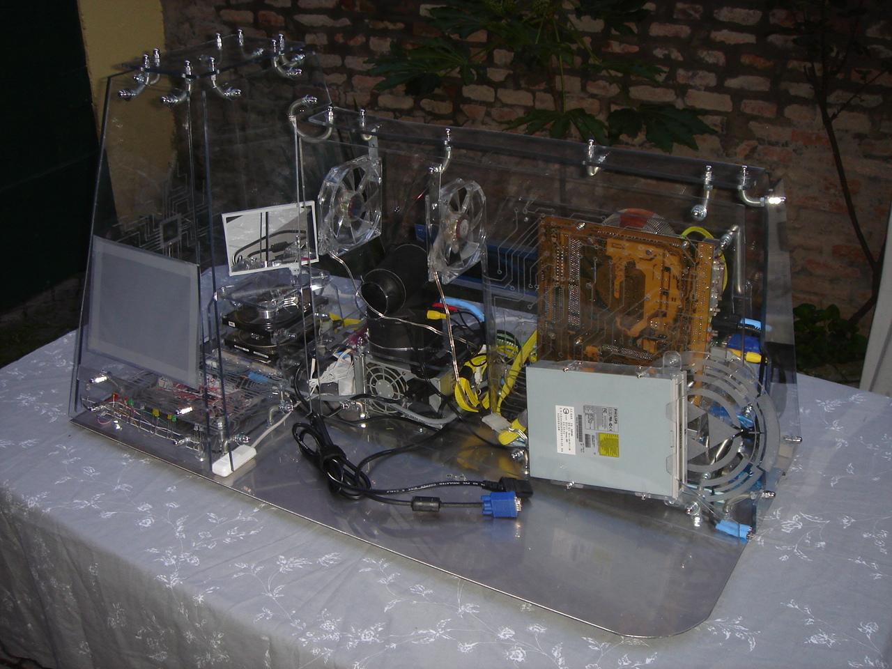
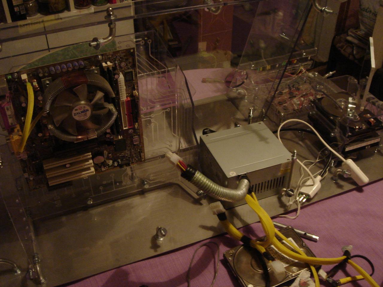
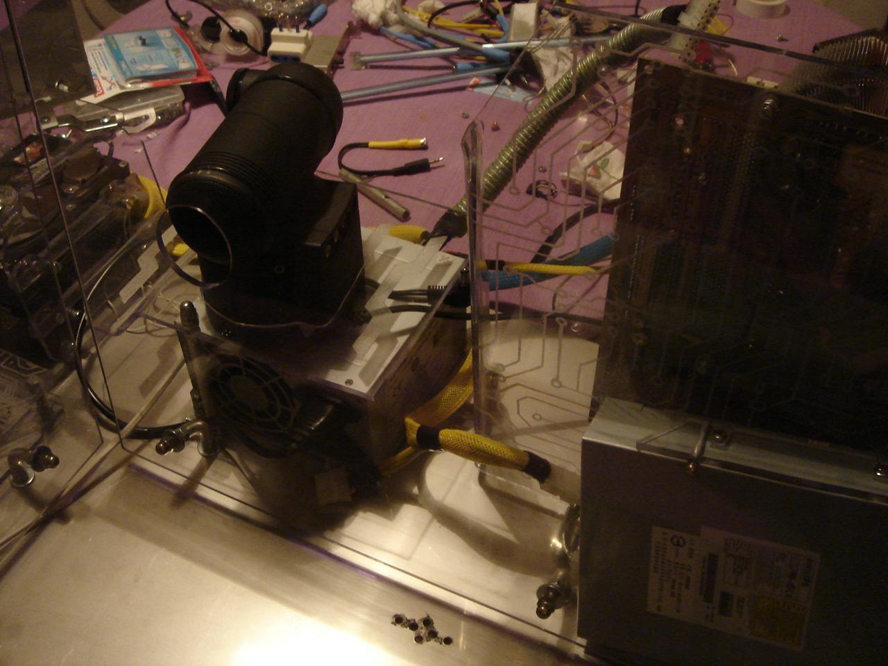
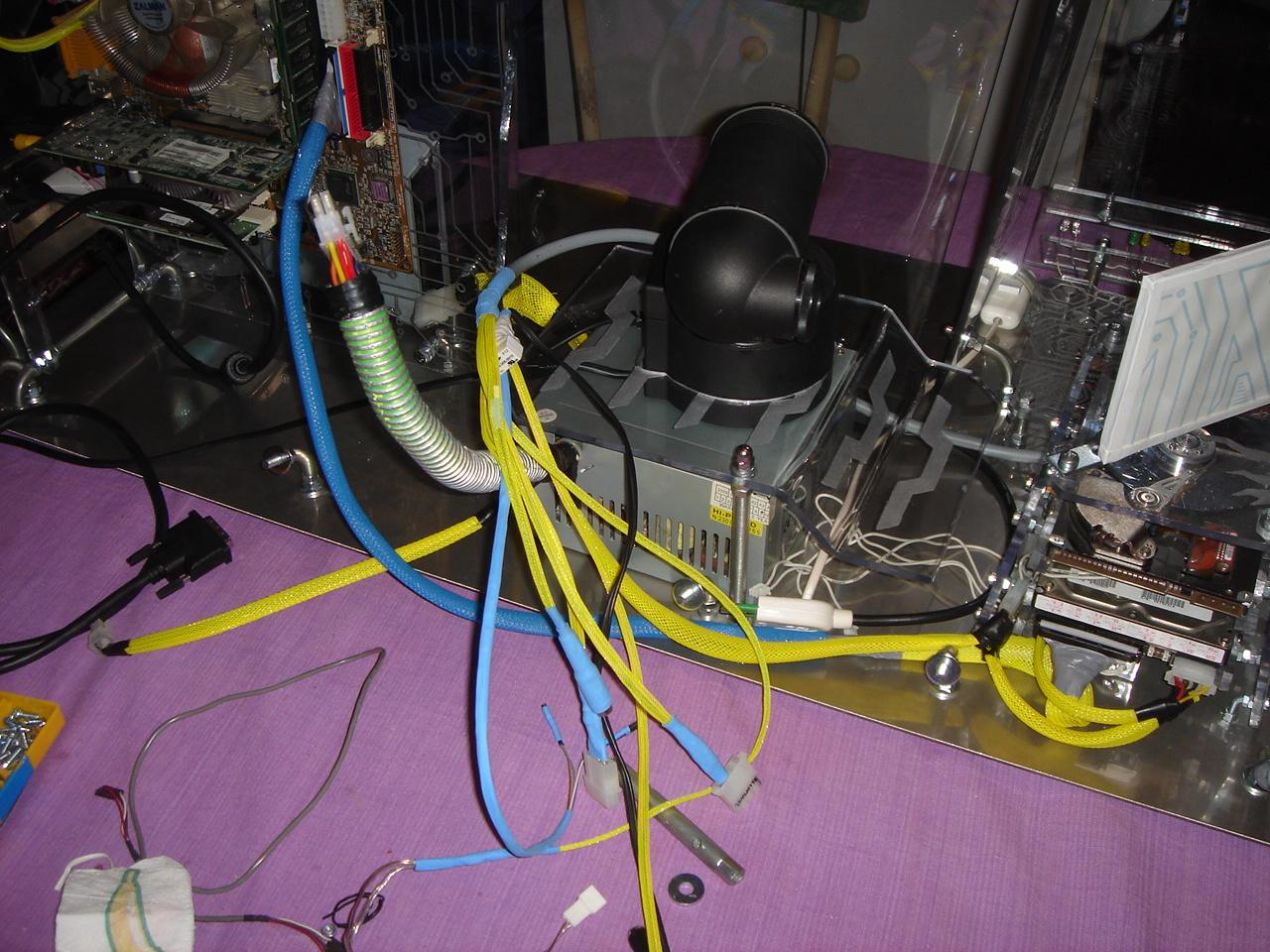
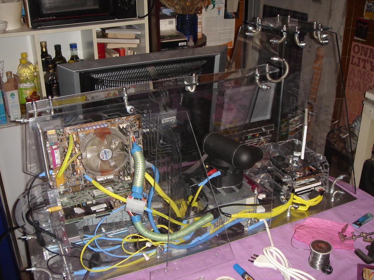
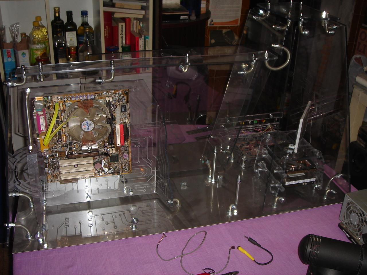
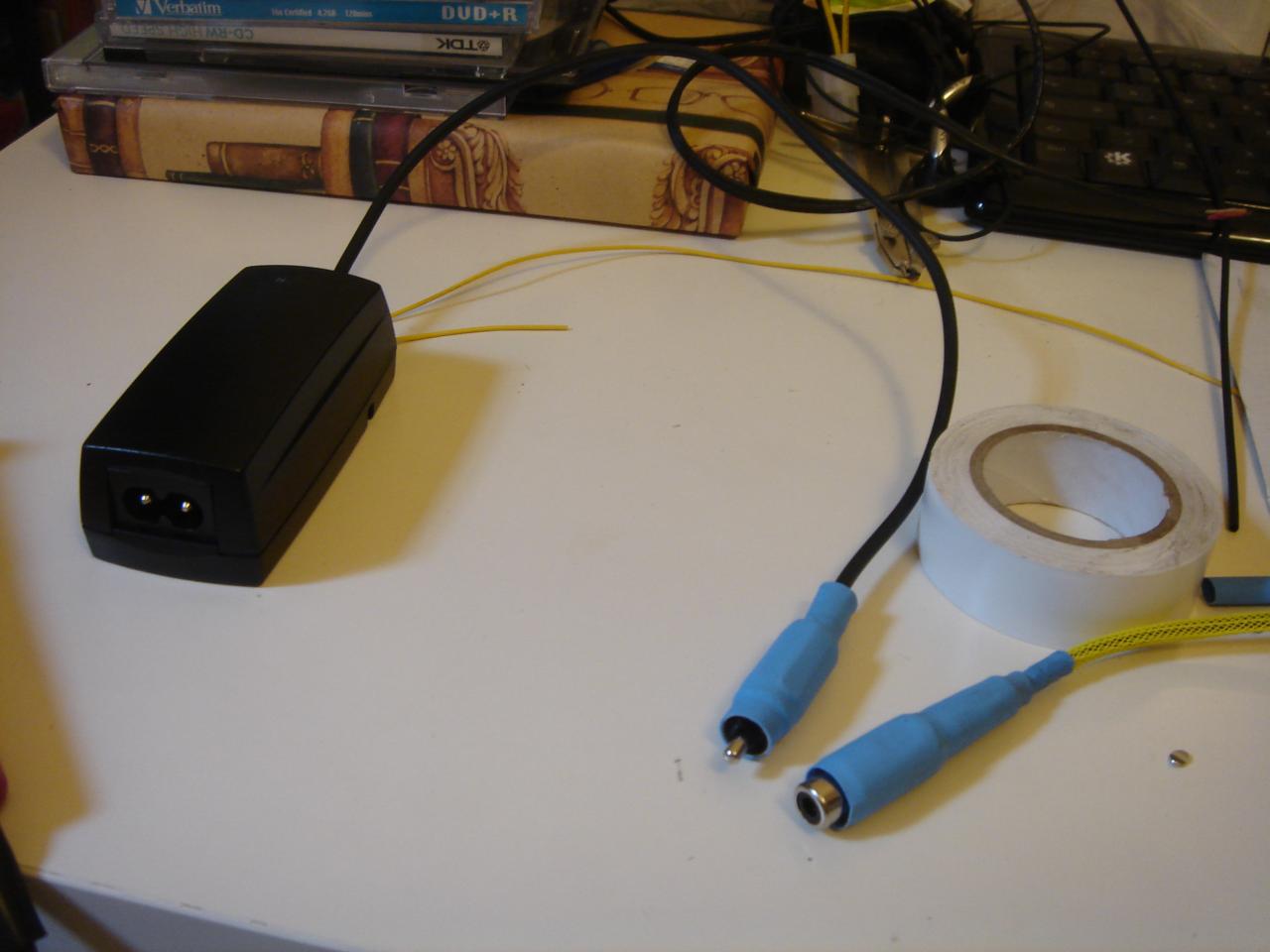
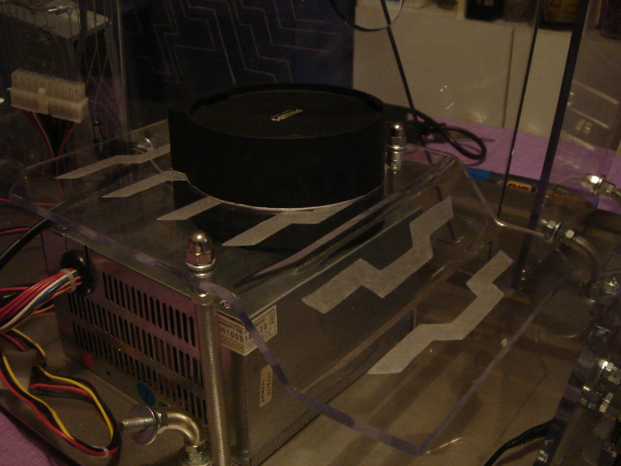
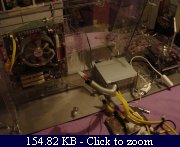
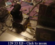
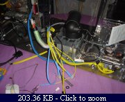
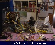
The PSU (mounting the PSU I discovered that the motherboard cable was too short.. I will make an extension):
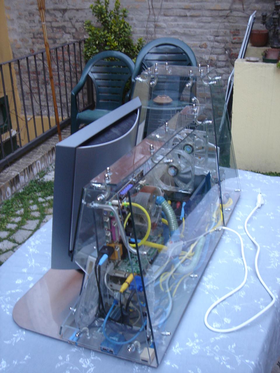
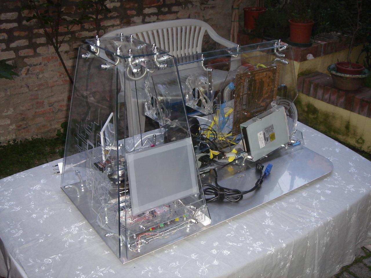
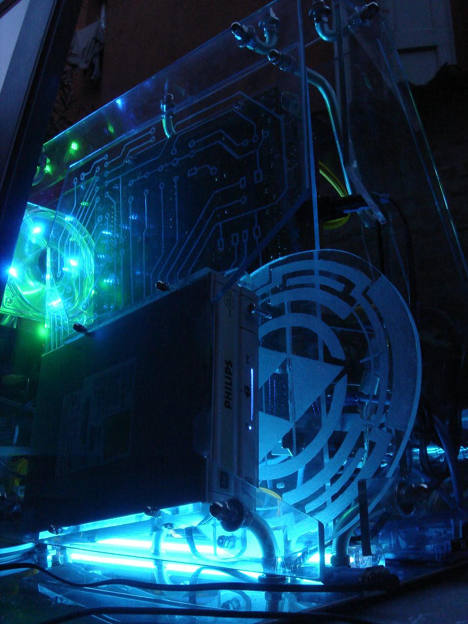
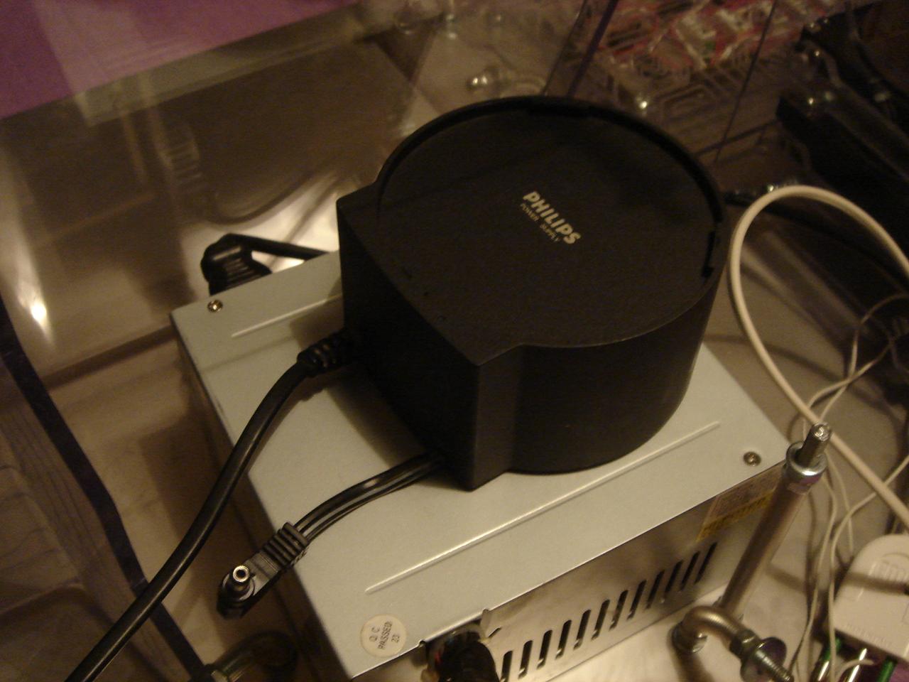
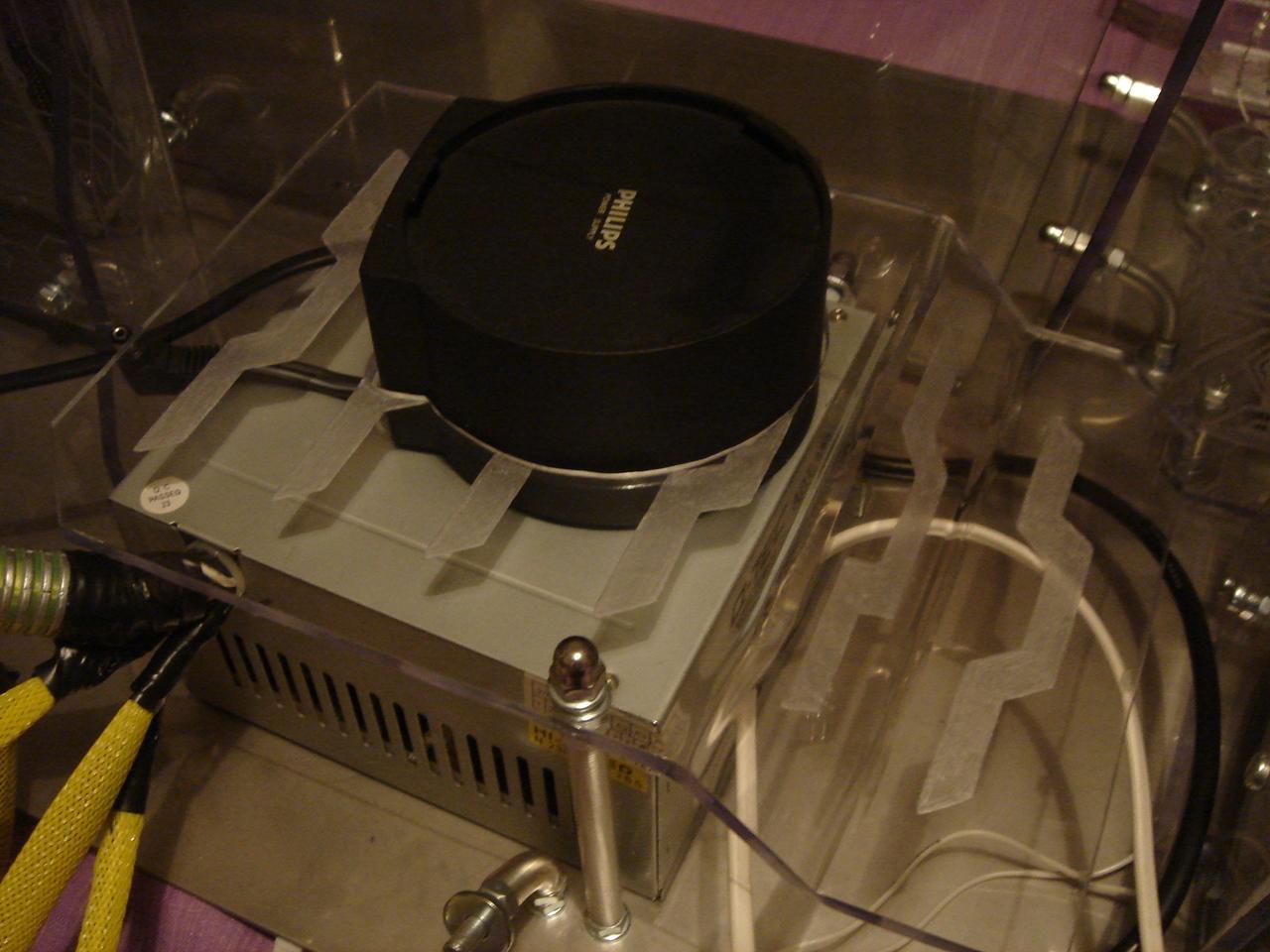
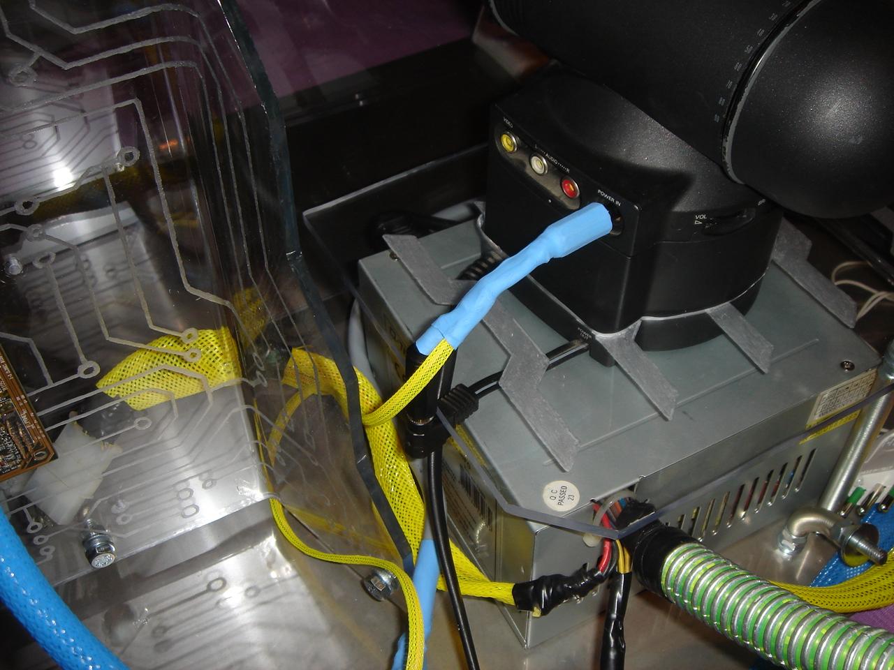
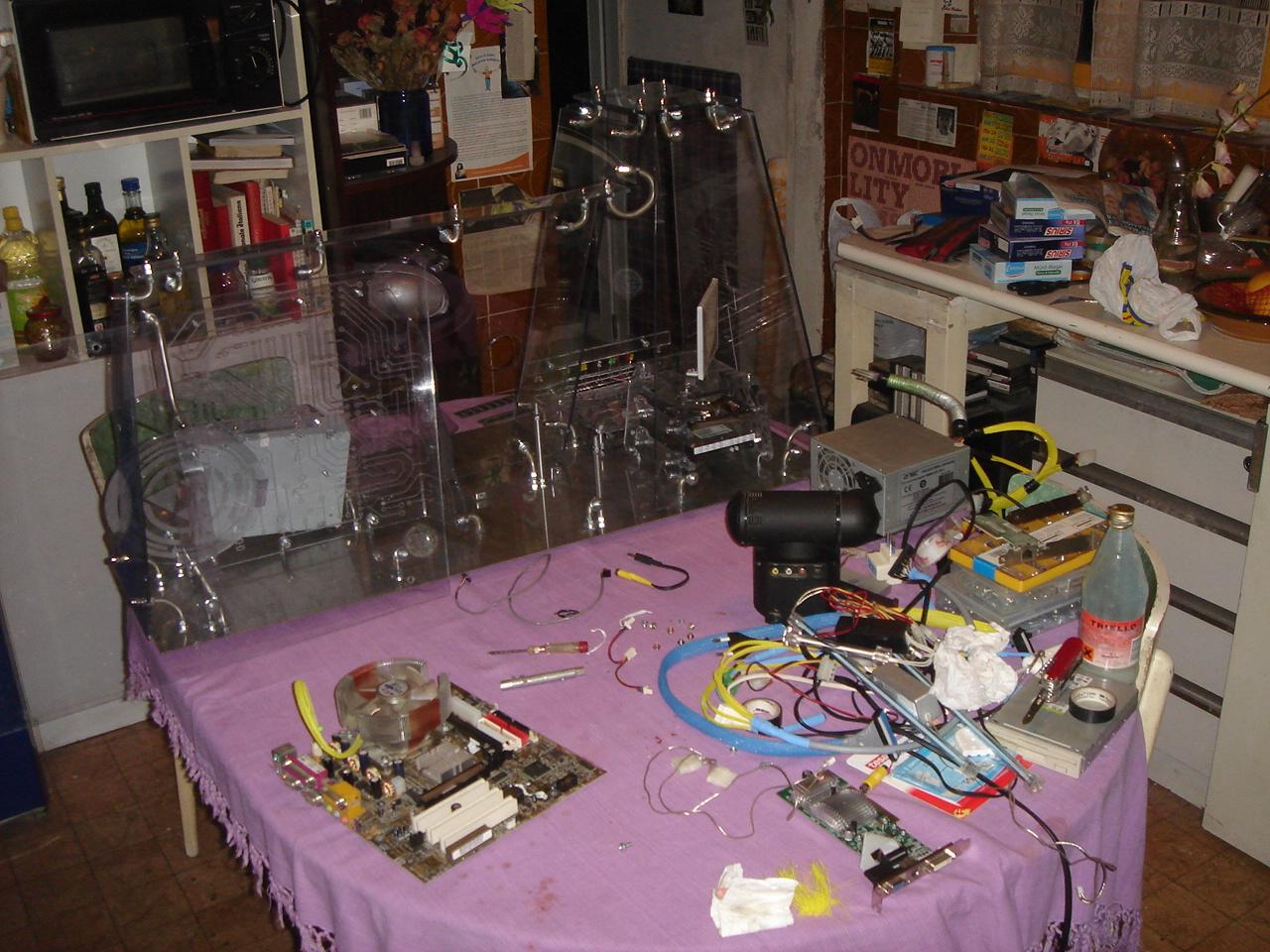
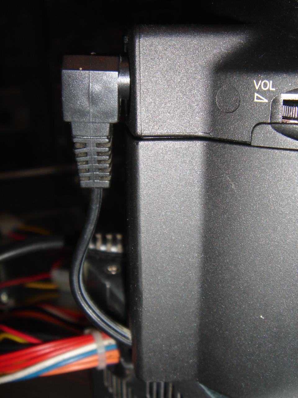
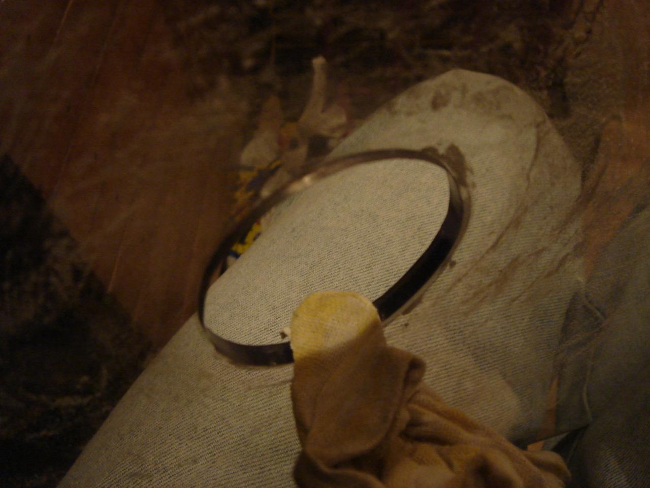
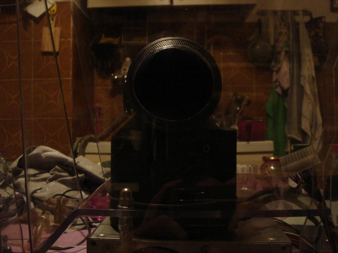
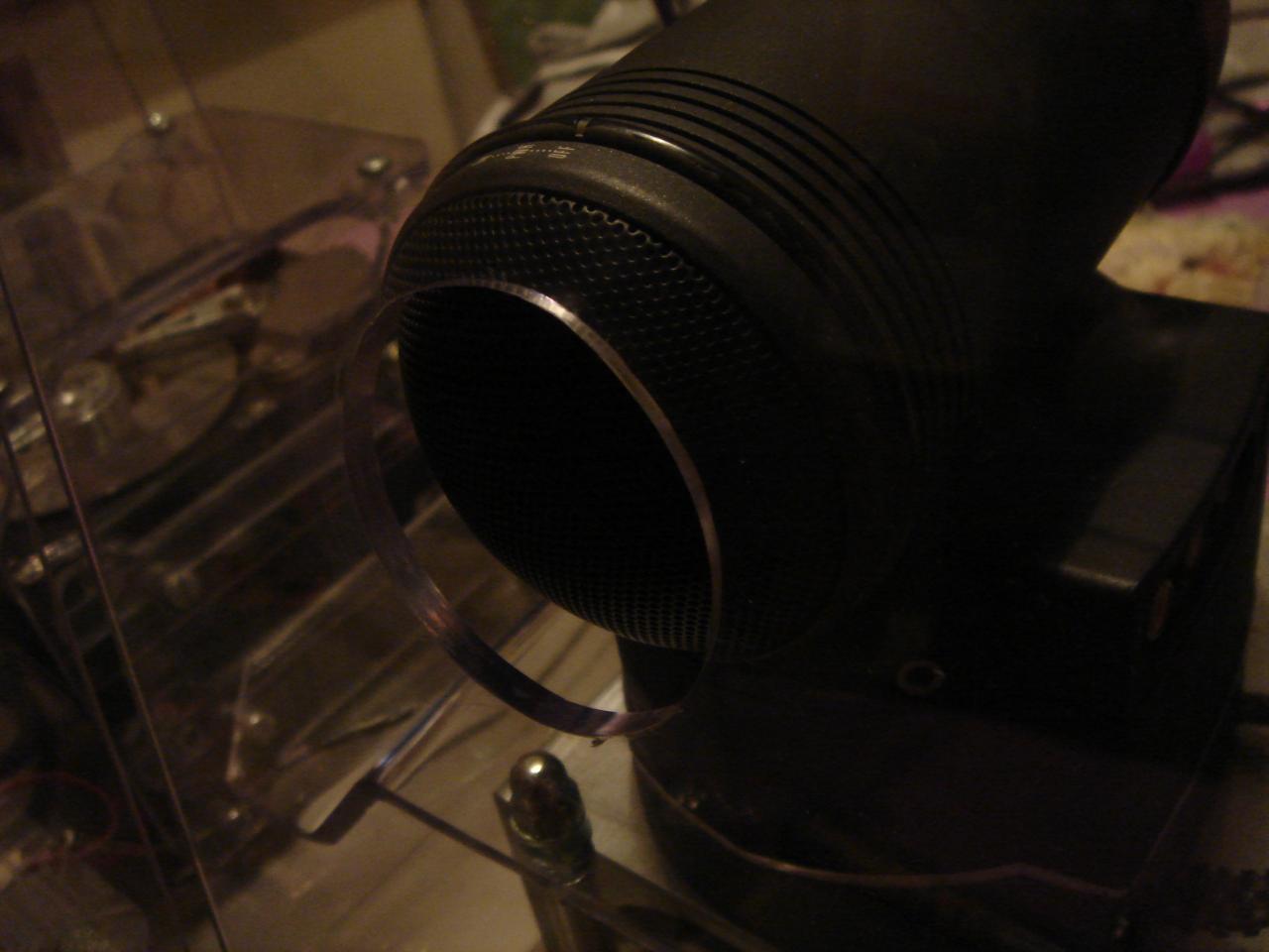
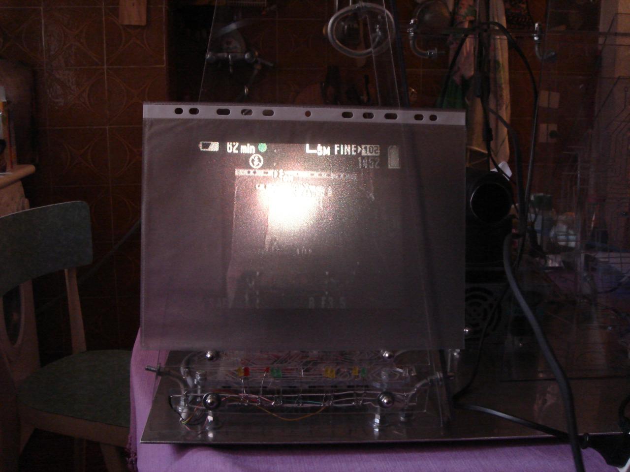
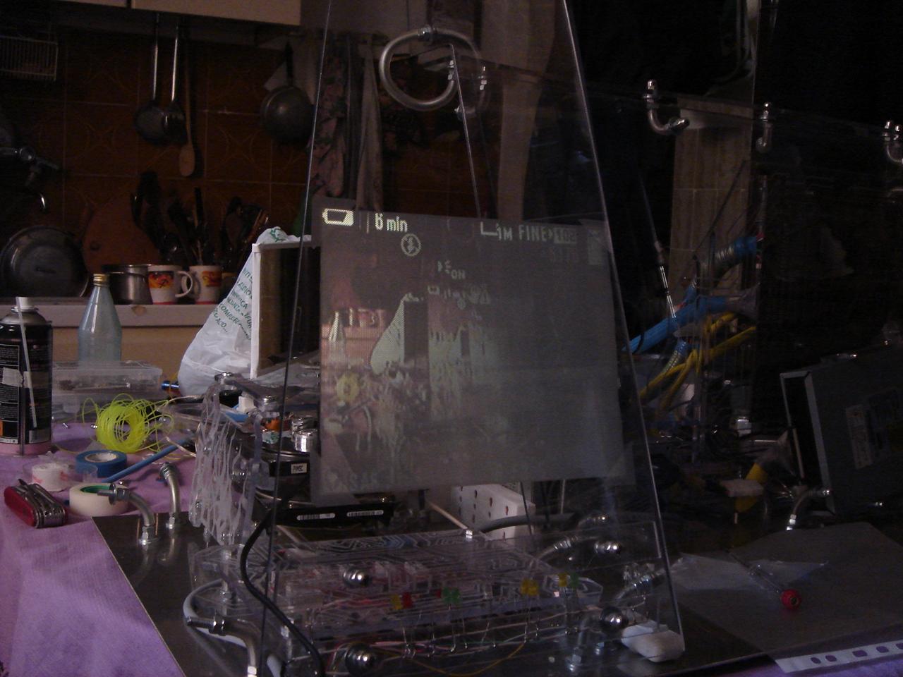
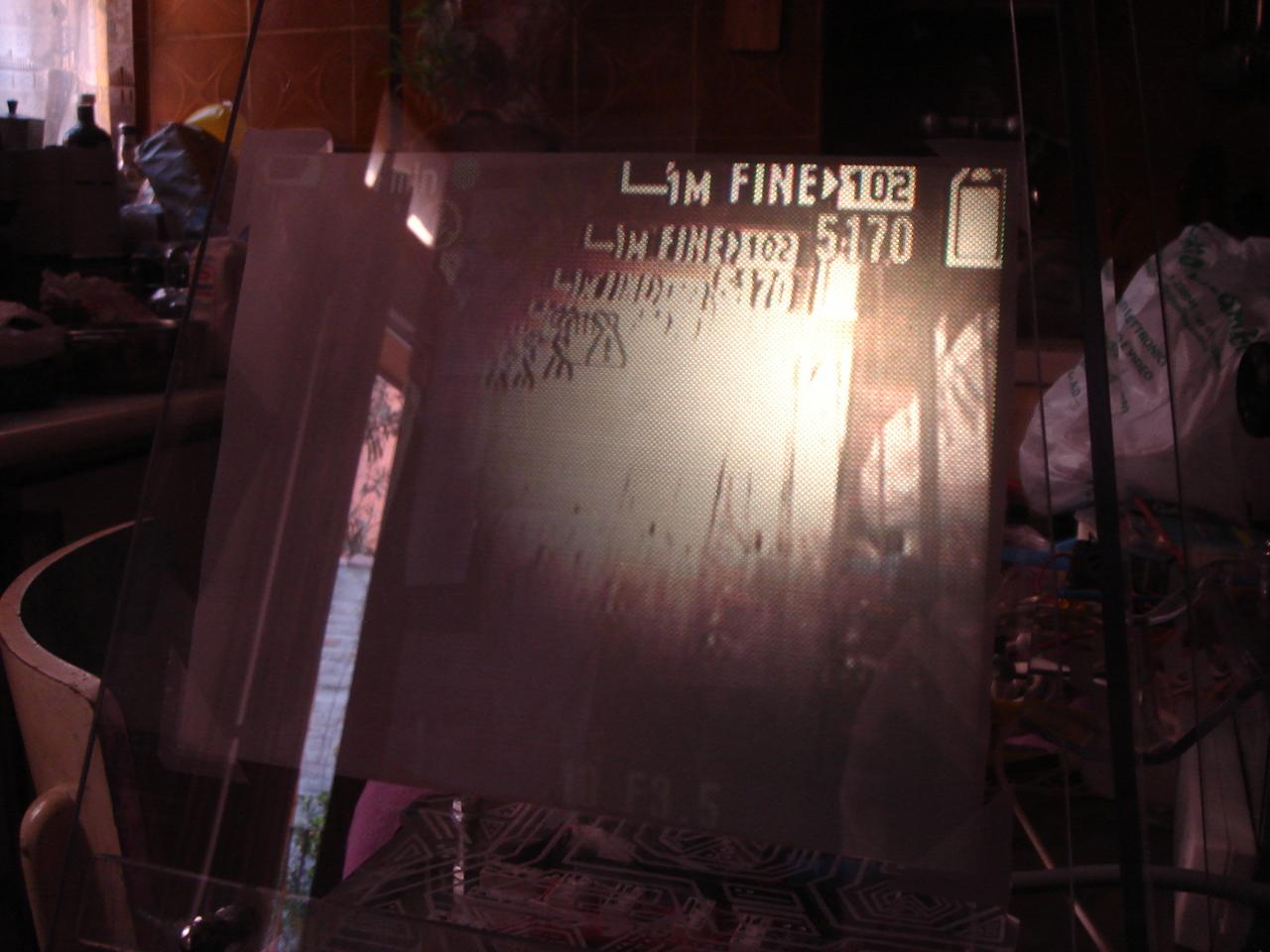
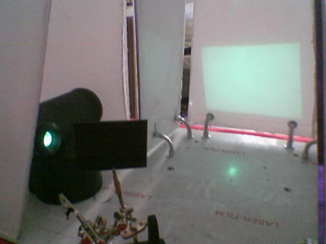
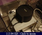
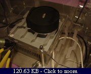
The videoprojector:

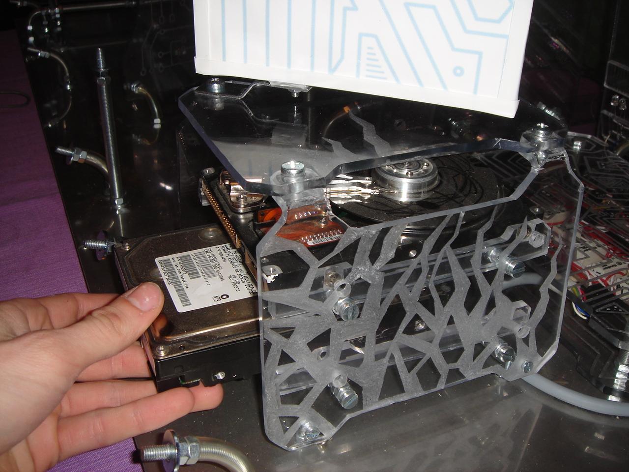
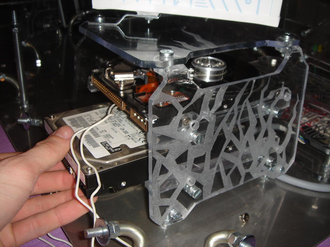
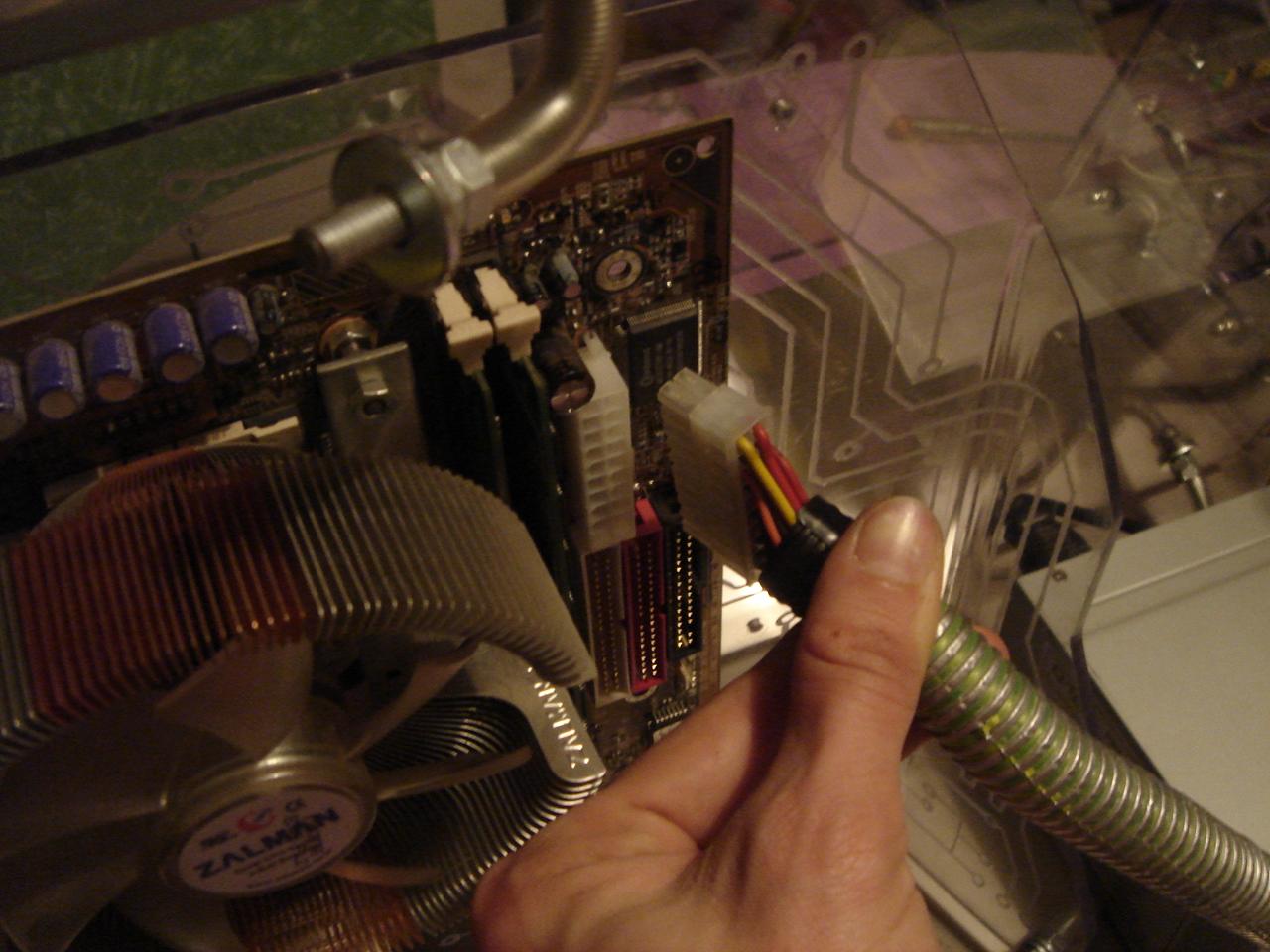
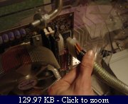
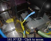
I plug the hard disk molex (for now I have only one hard disk, so in the second slot I keep the opened hard disk):

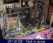
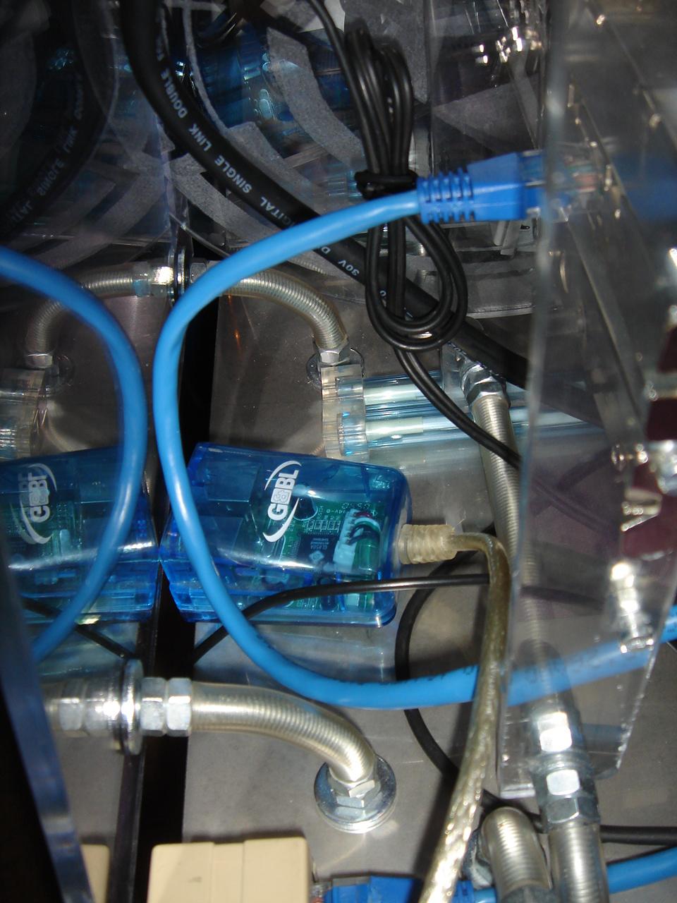
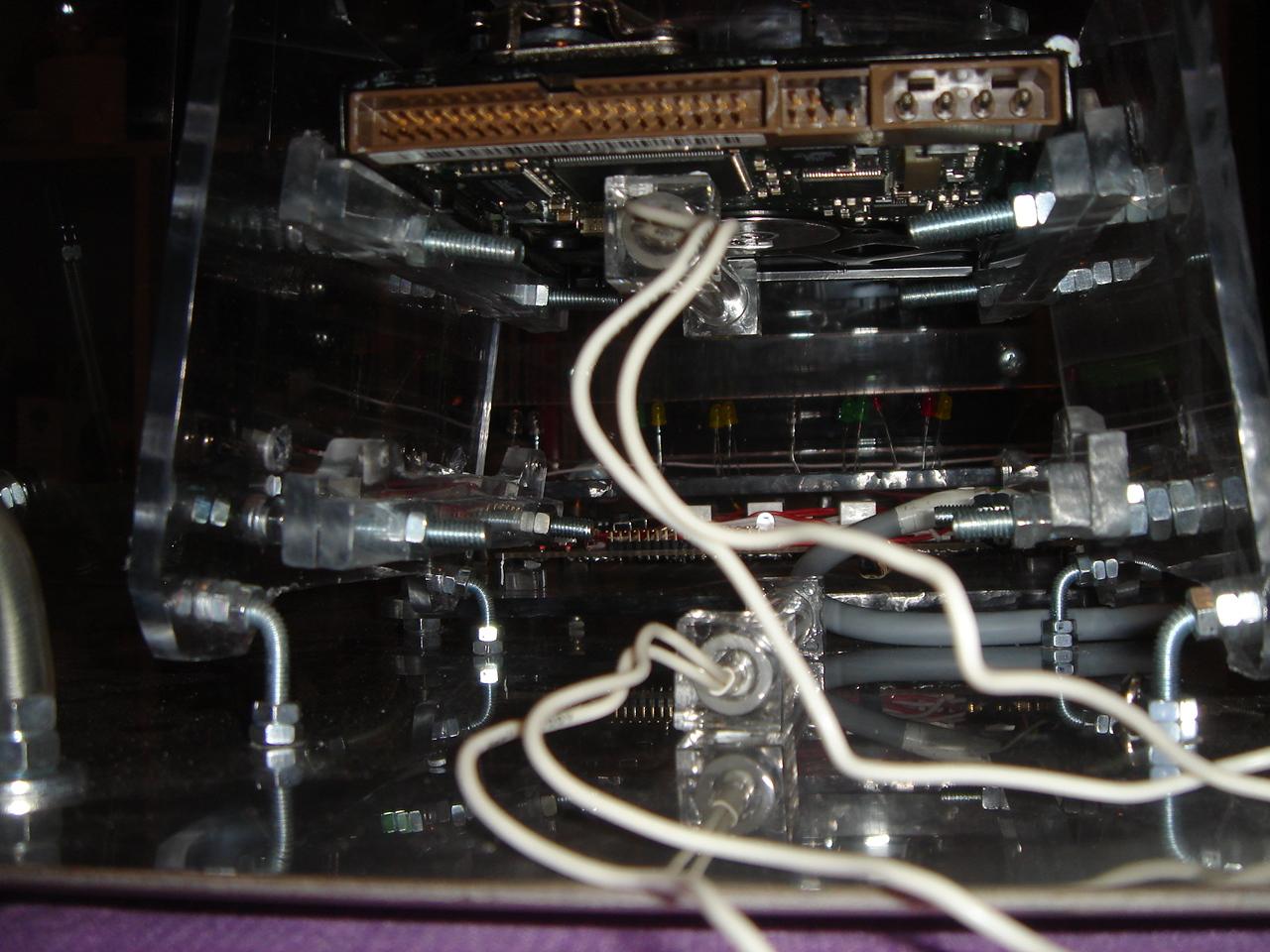
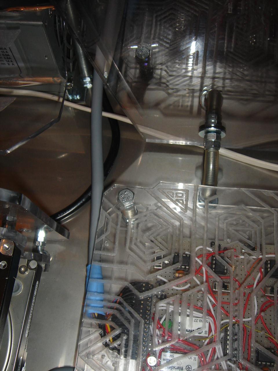
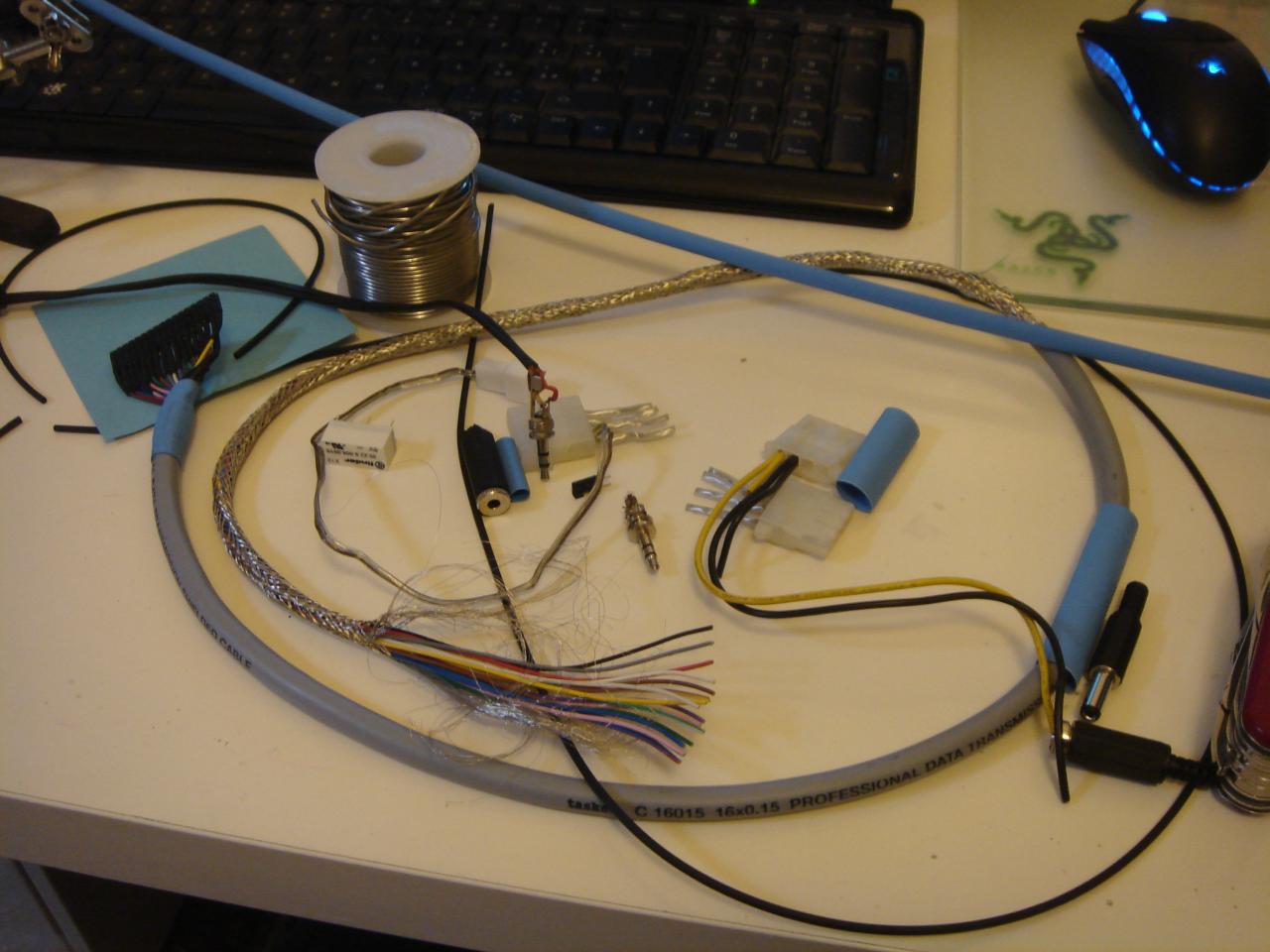
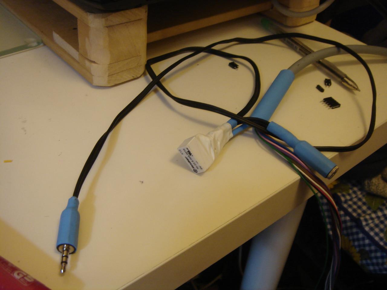
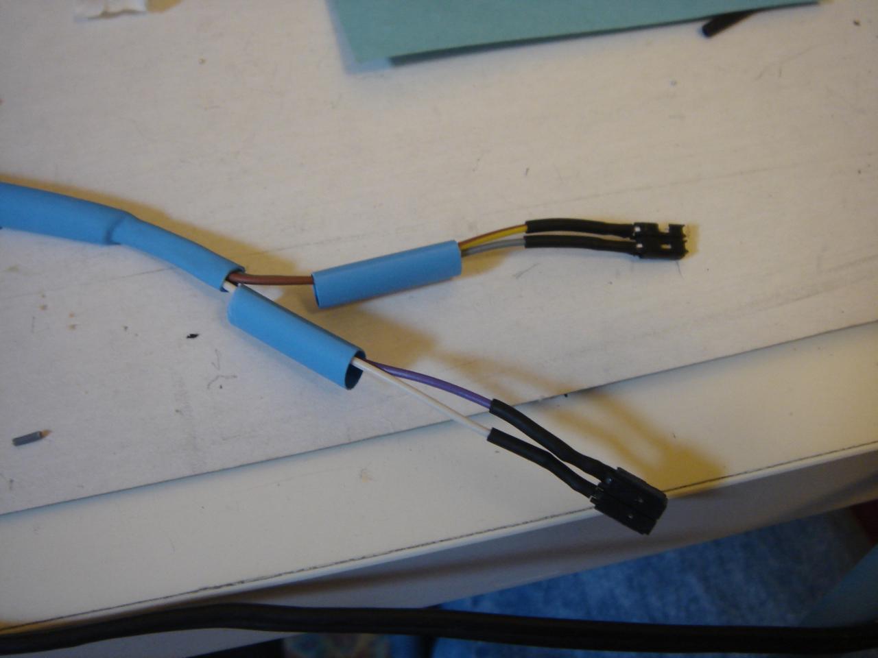
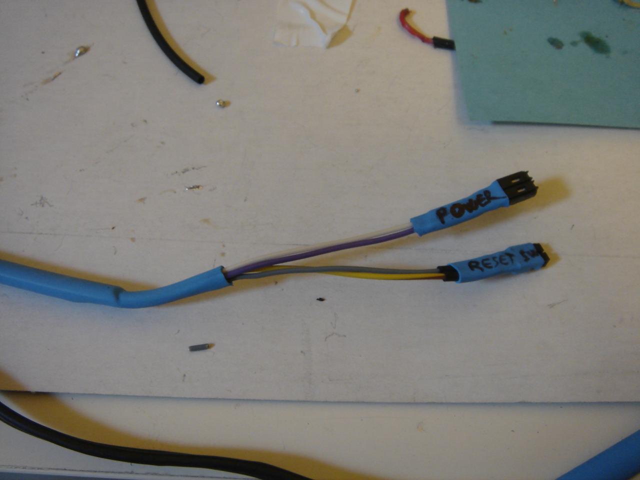
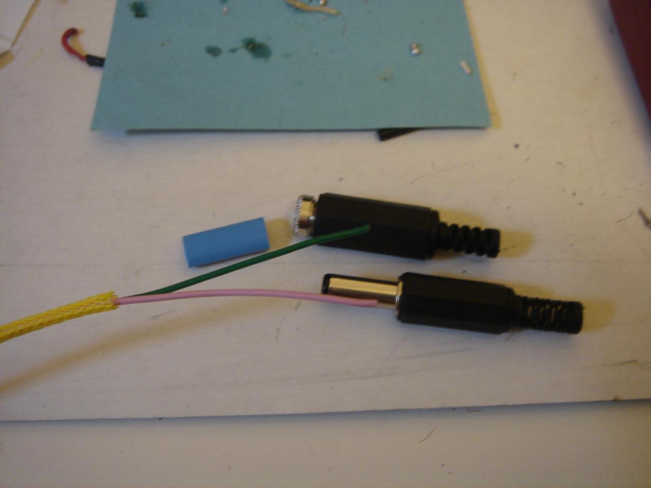
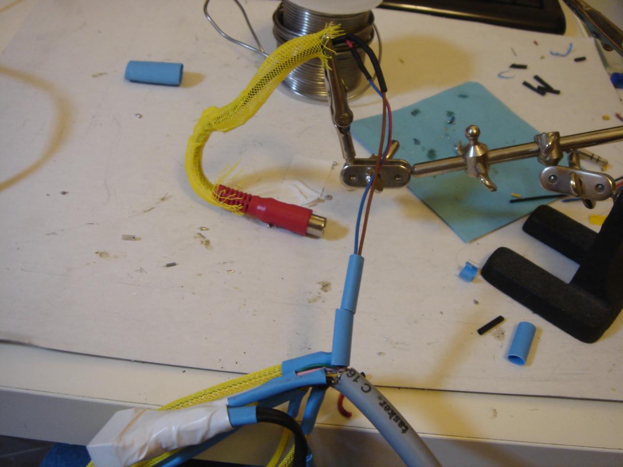
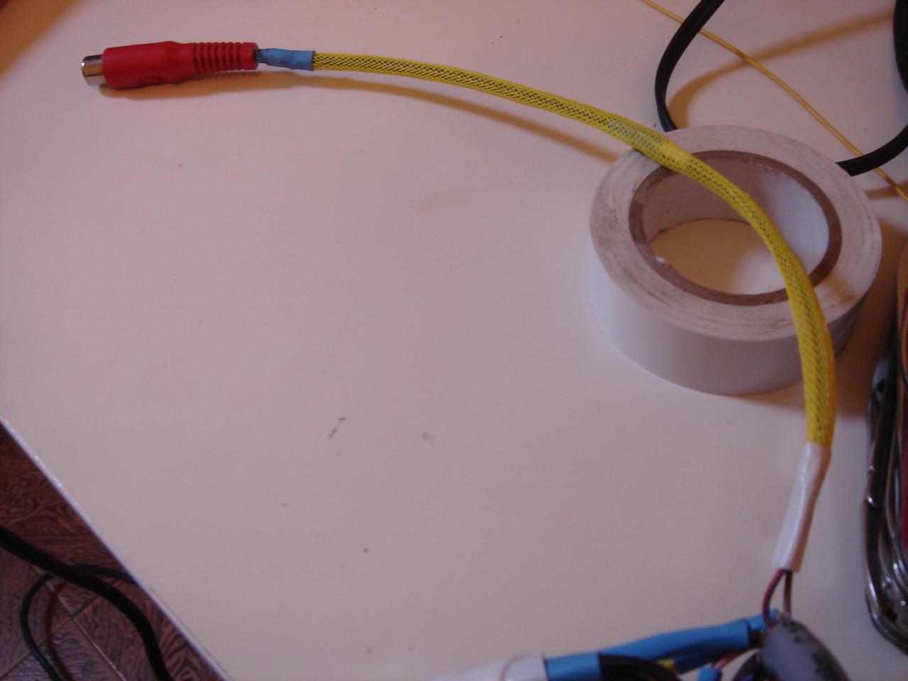
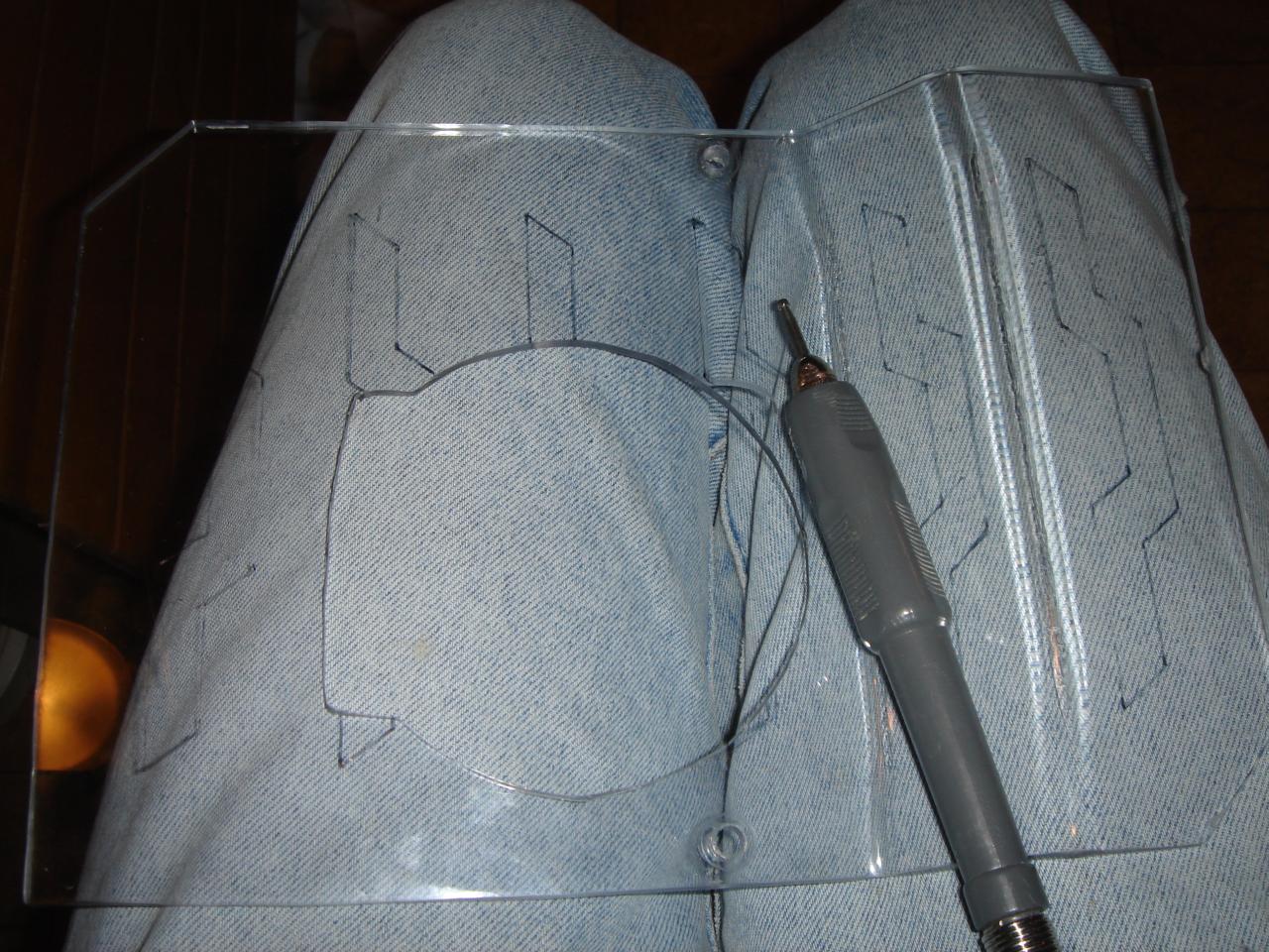
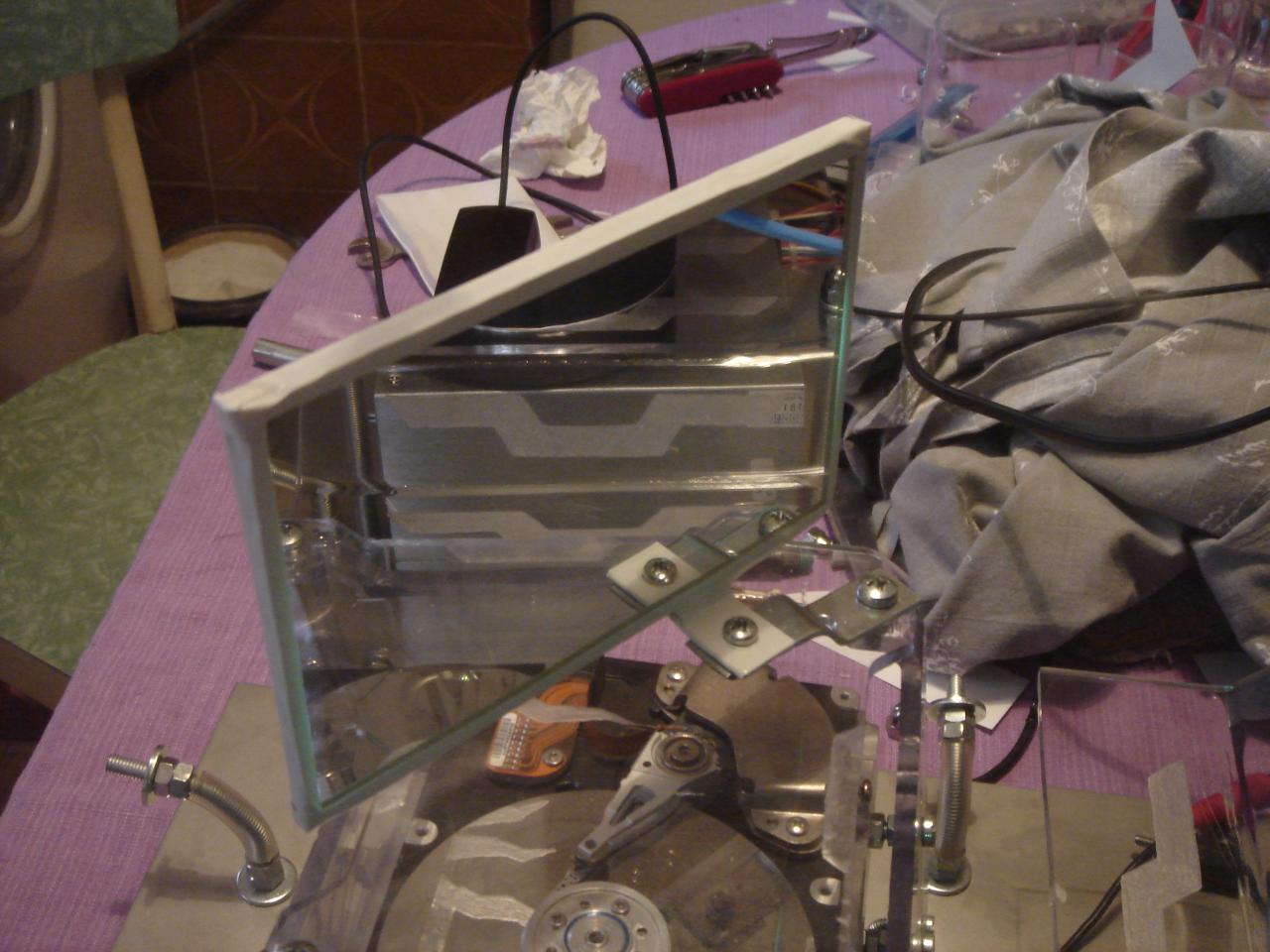
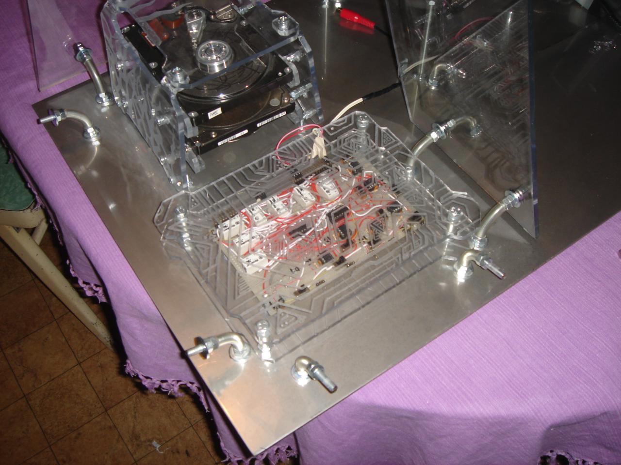
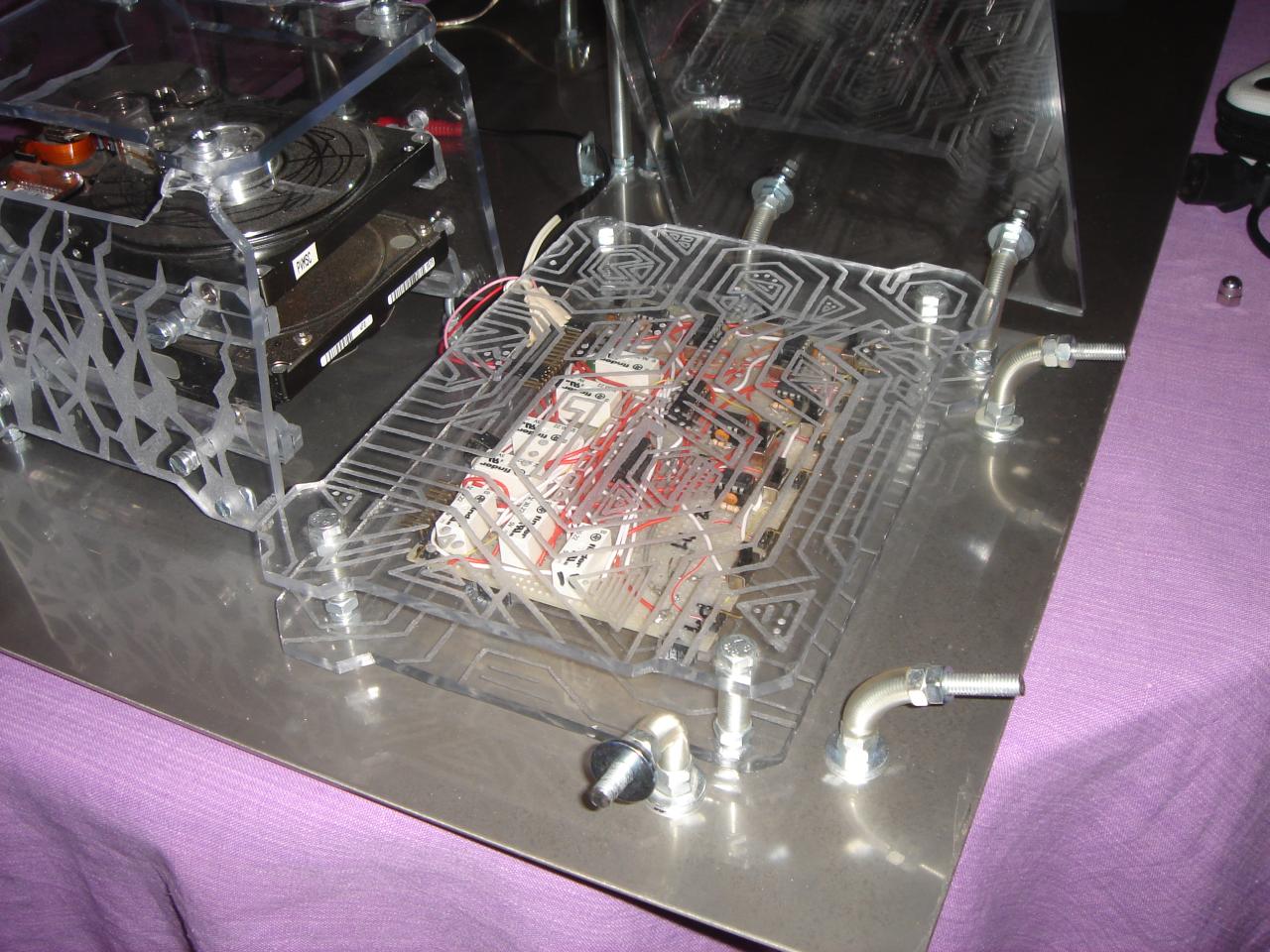
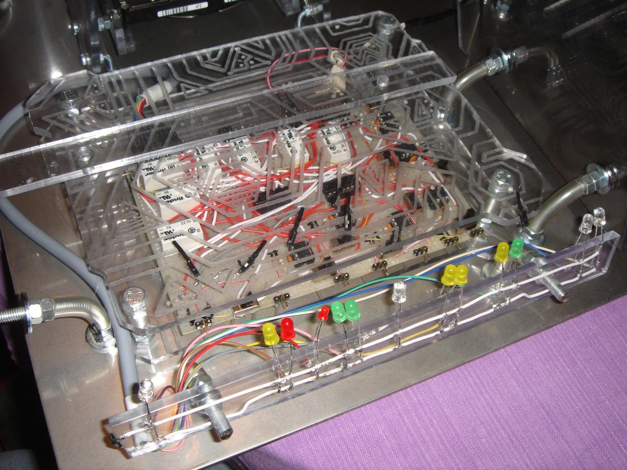
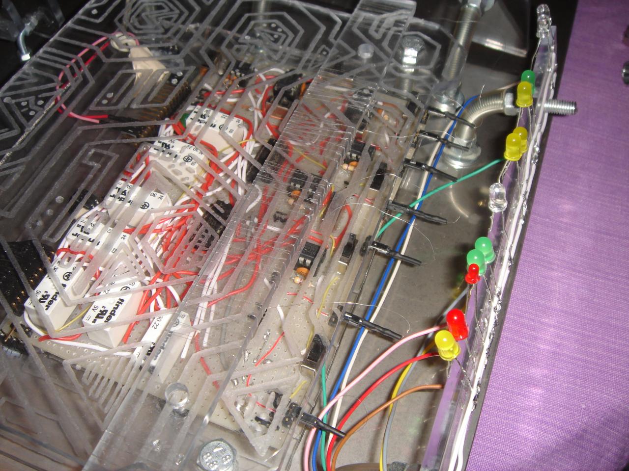
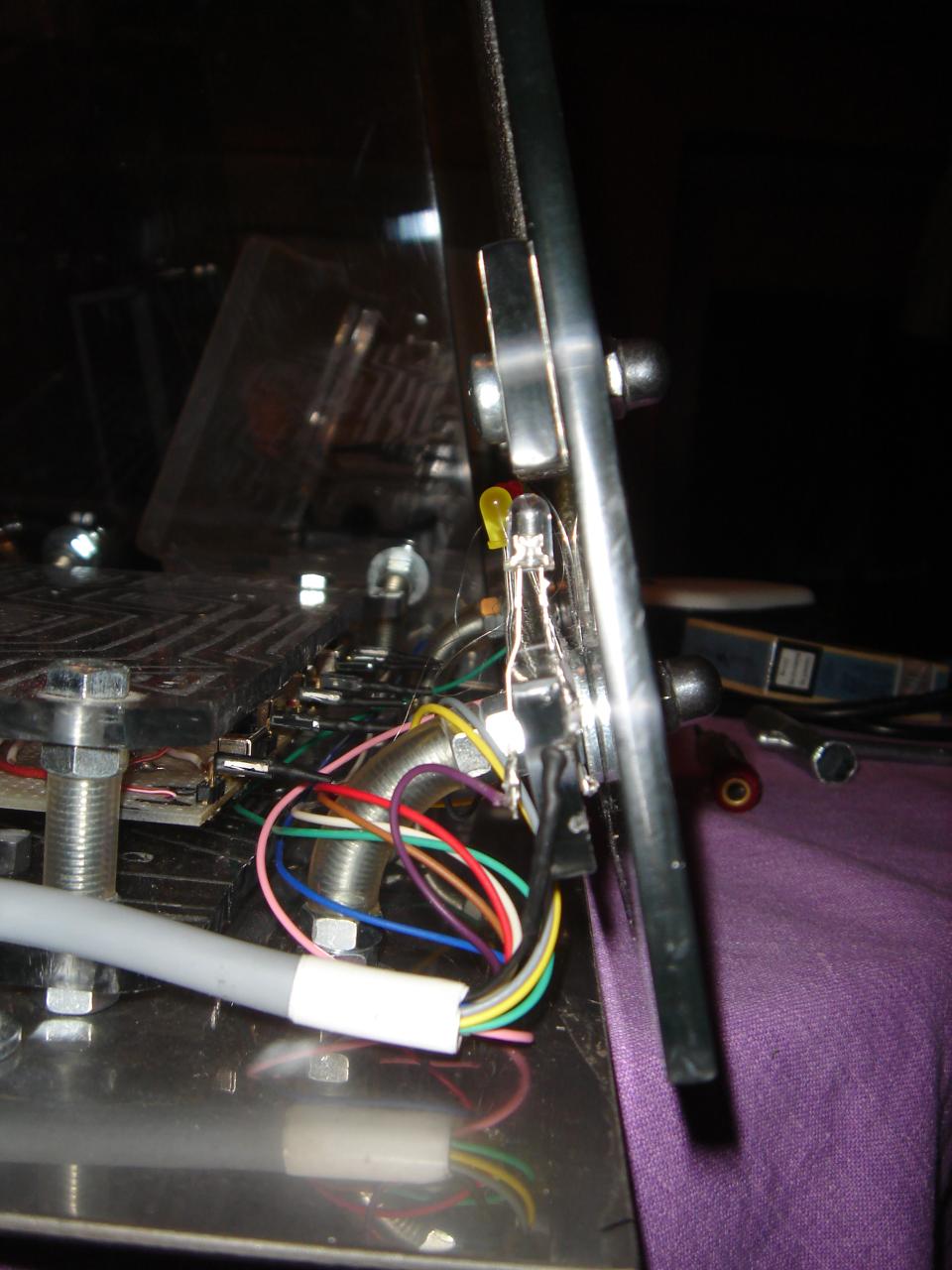
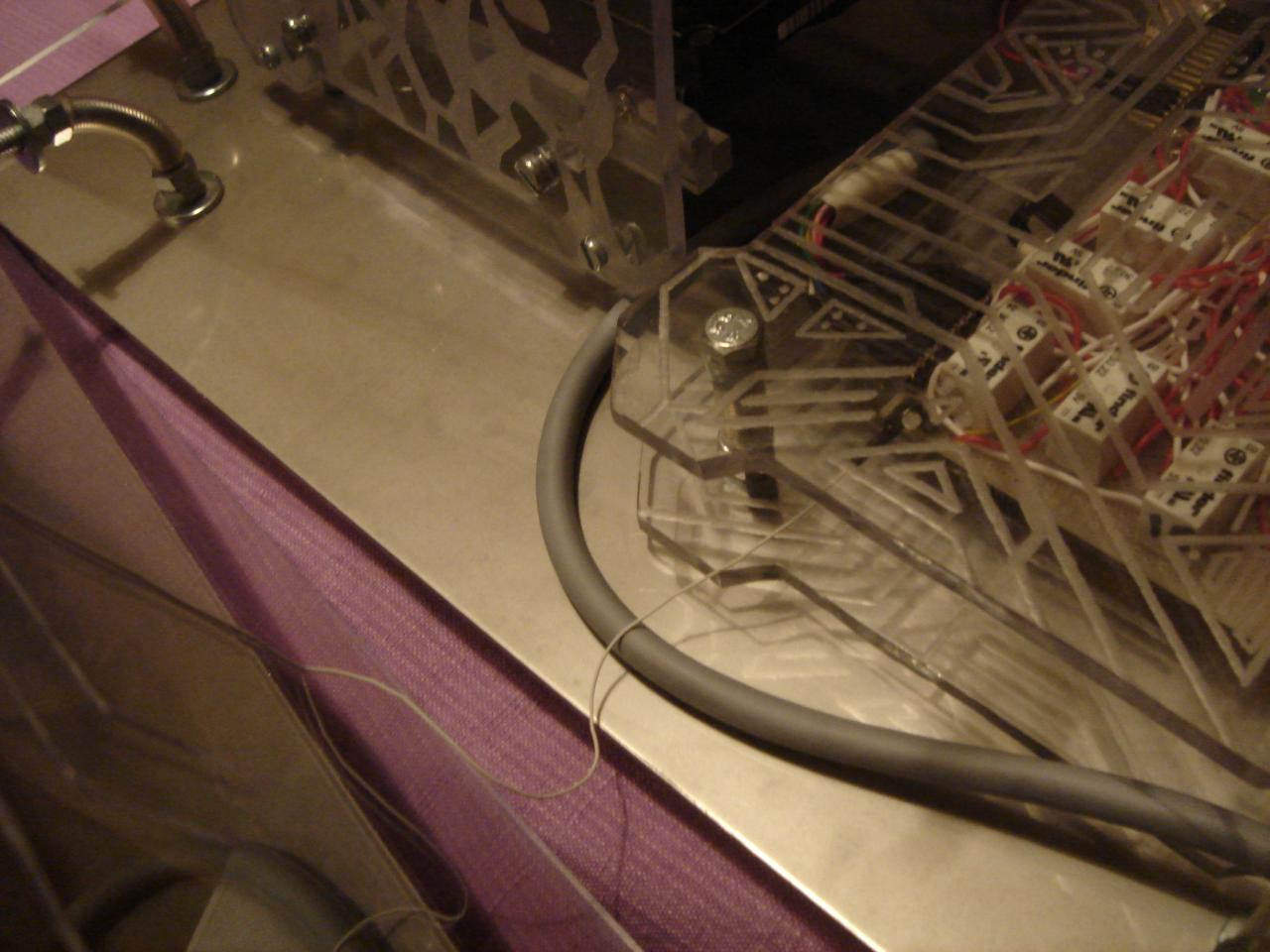
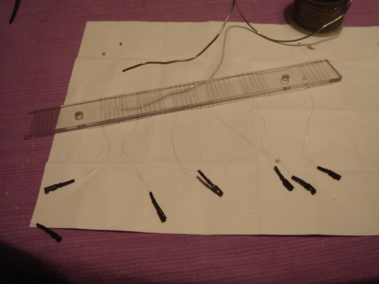
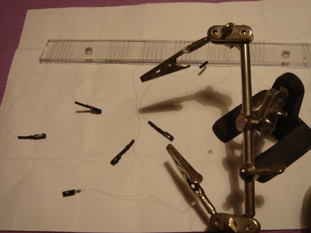
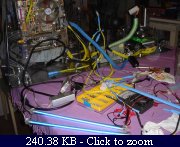
And I start to connect the touch sensors circuit cable to the components:

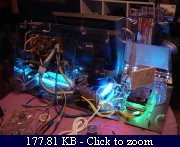
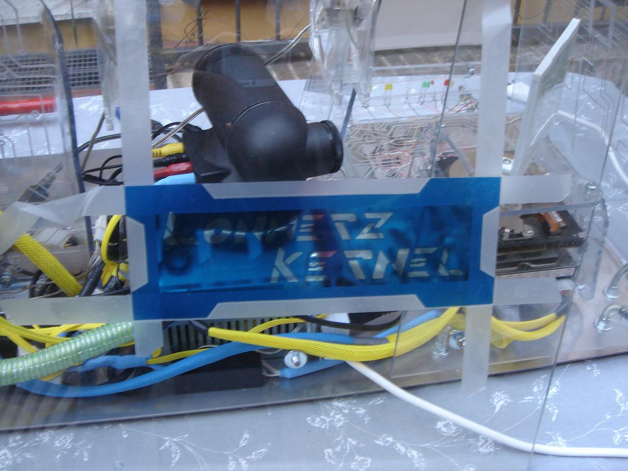
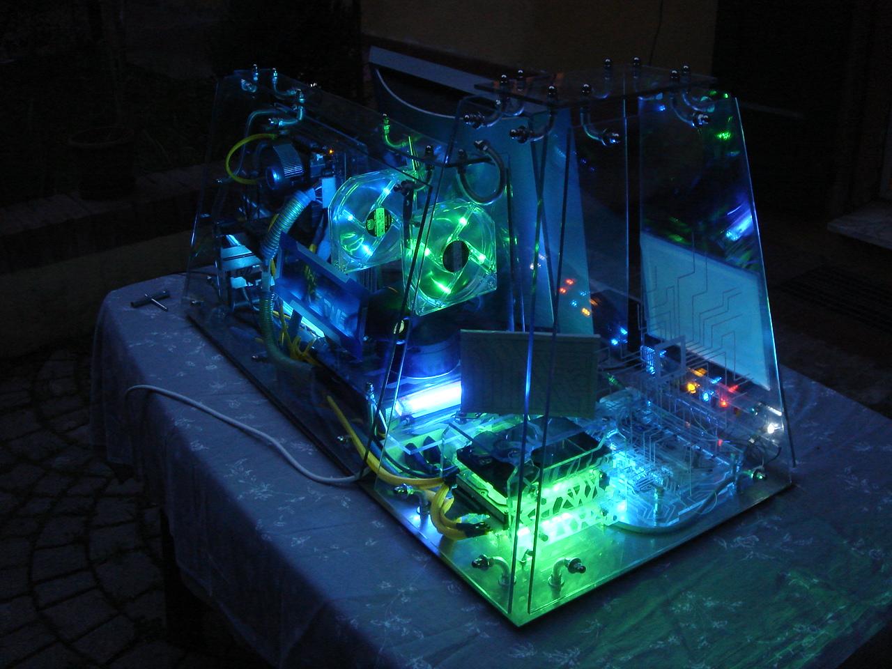
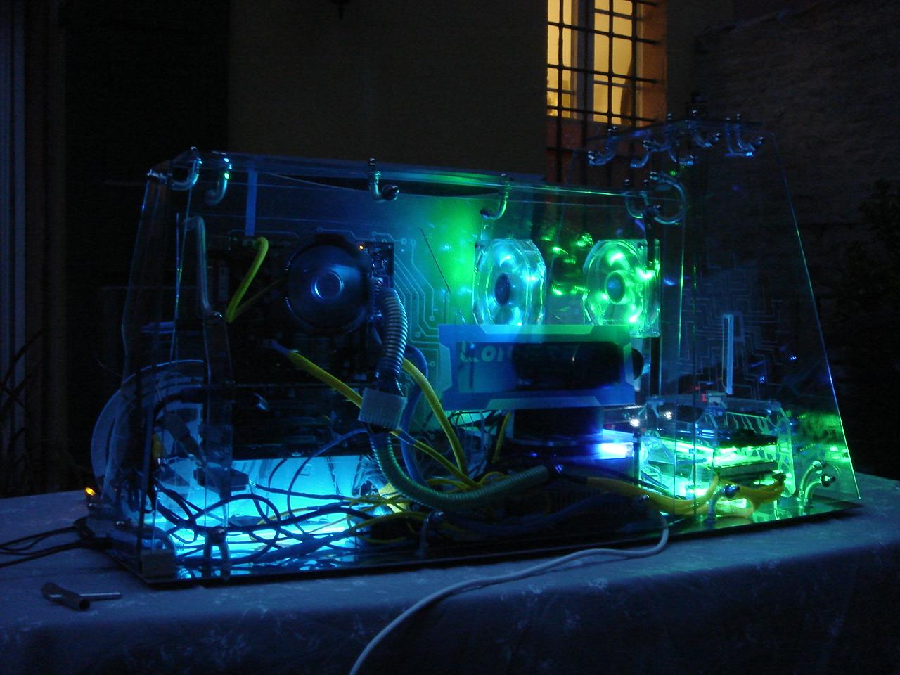
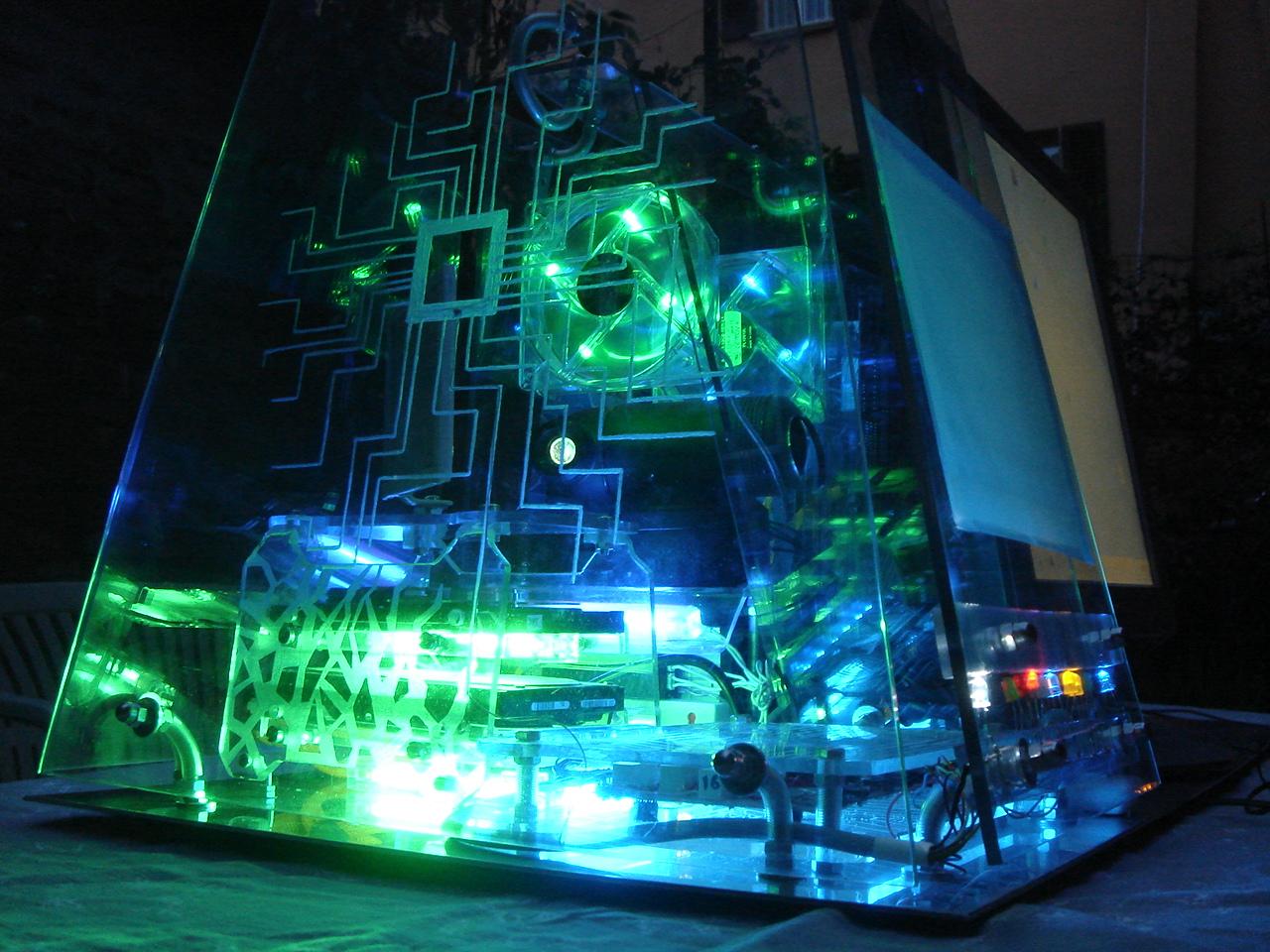
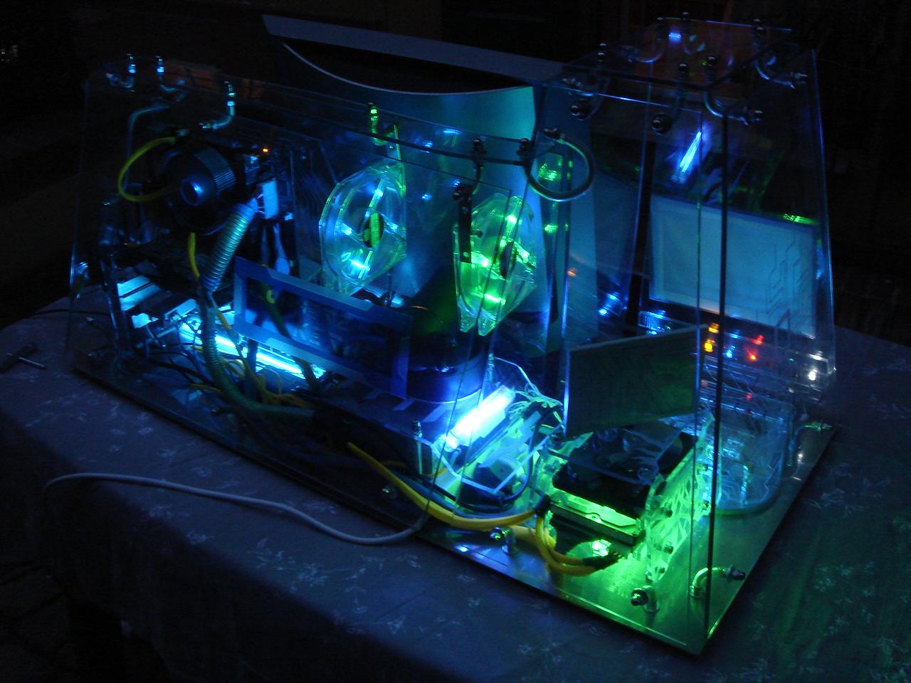
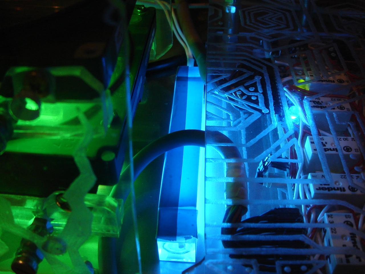
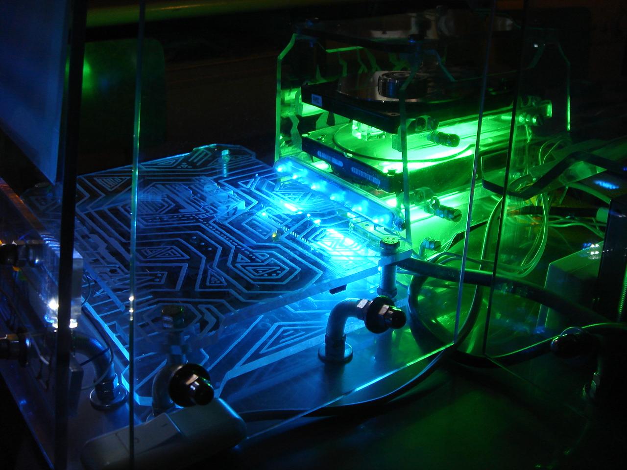
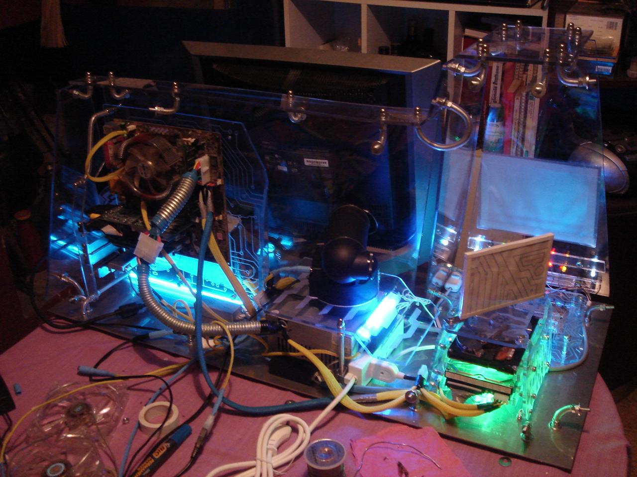
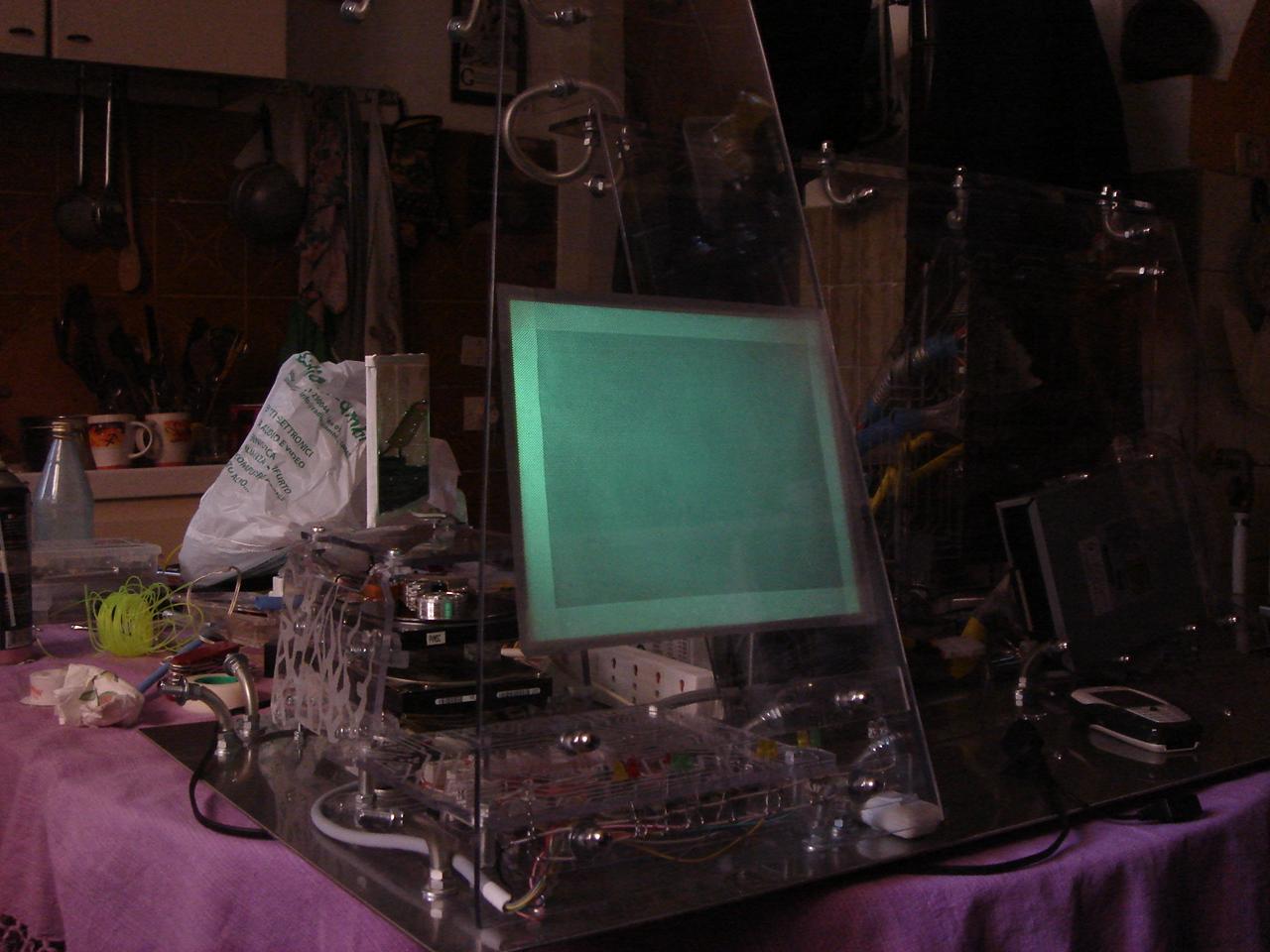
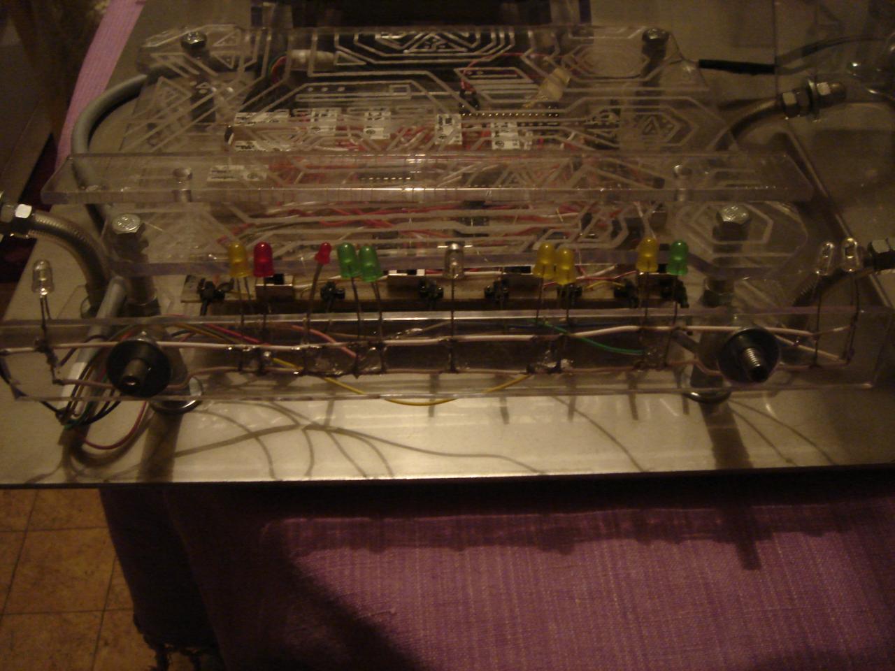
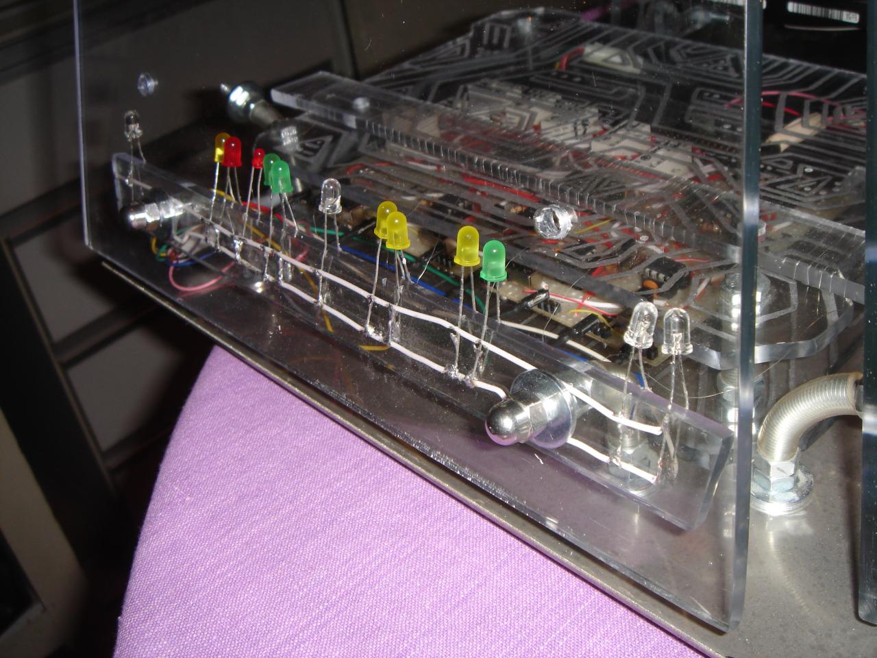
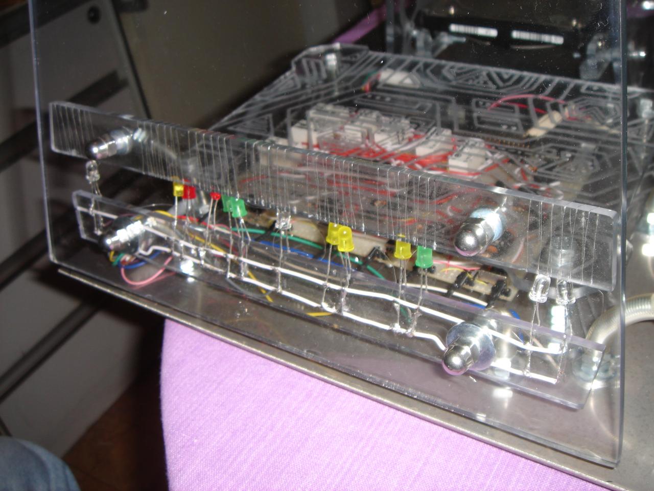
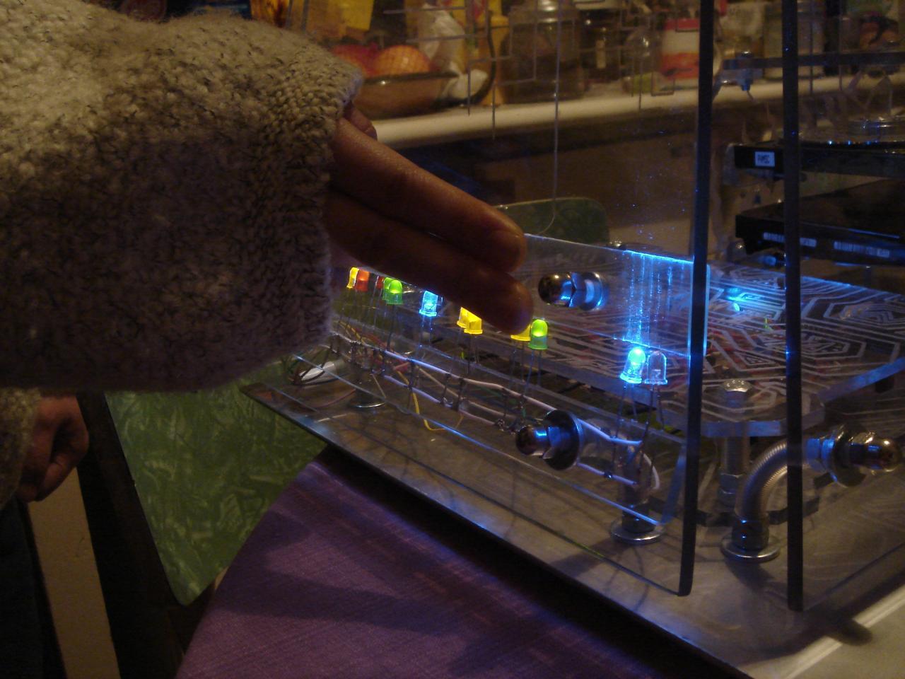
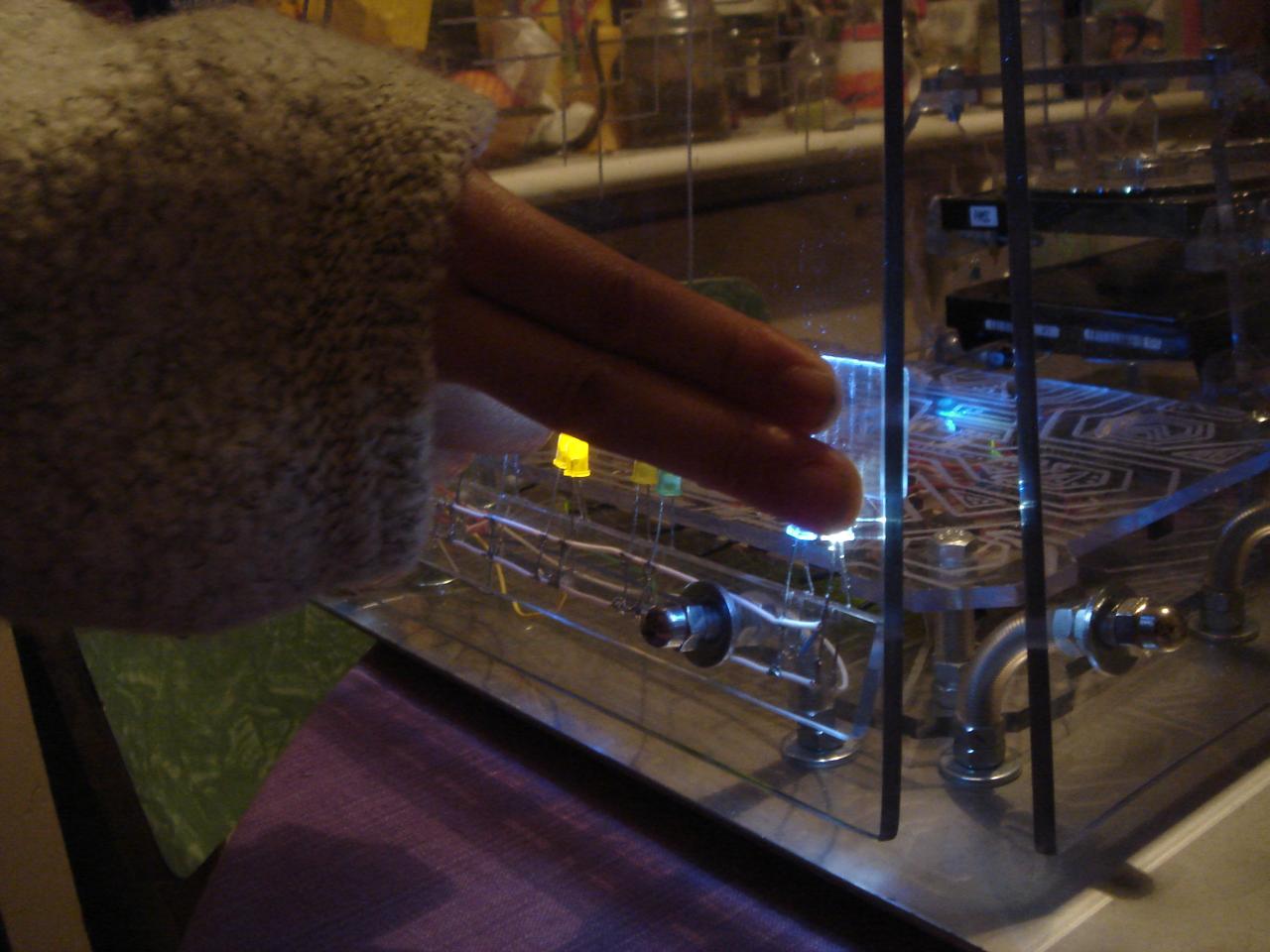
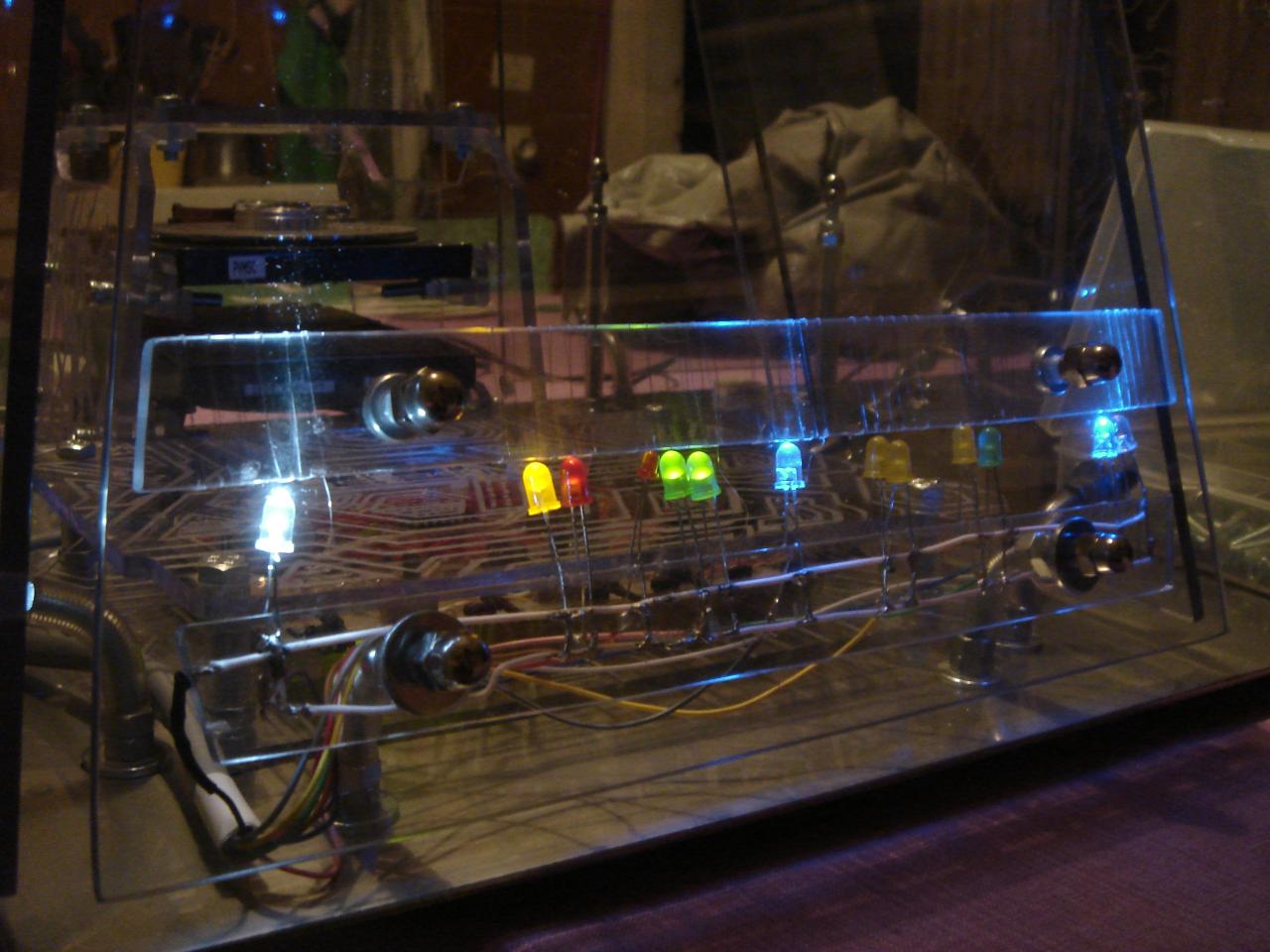
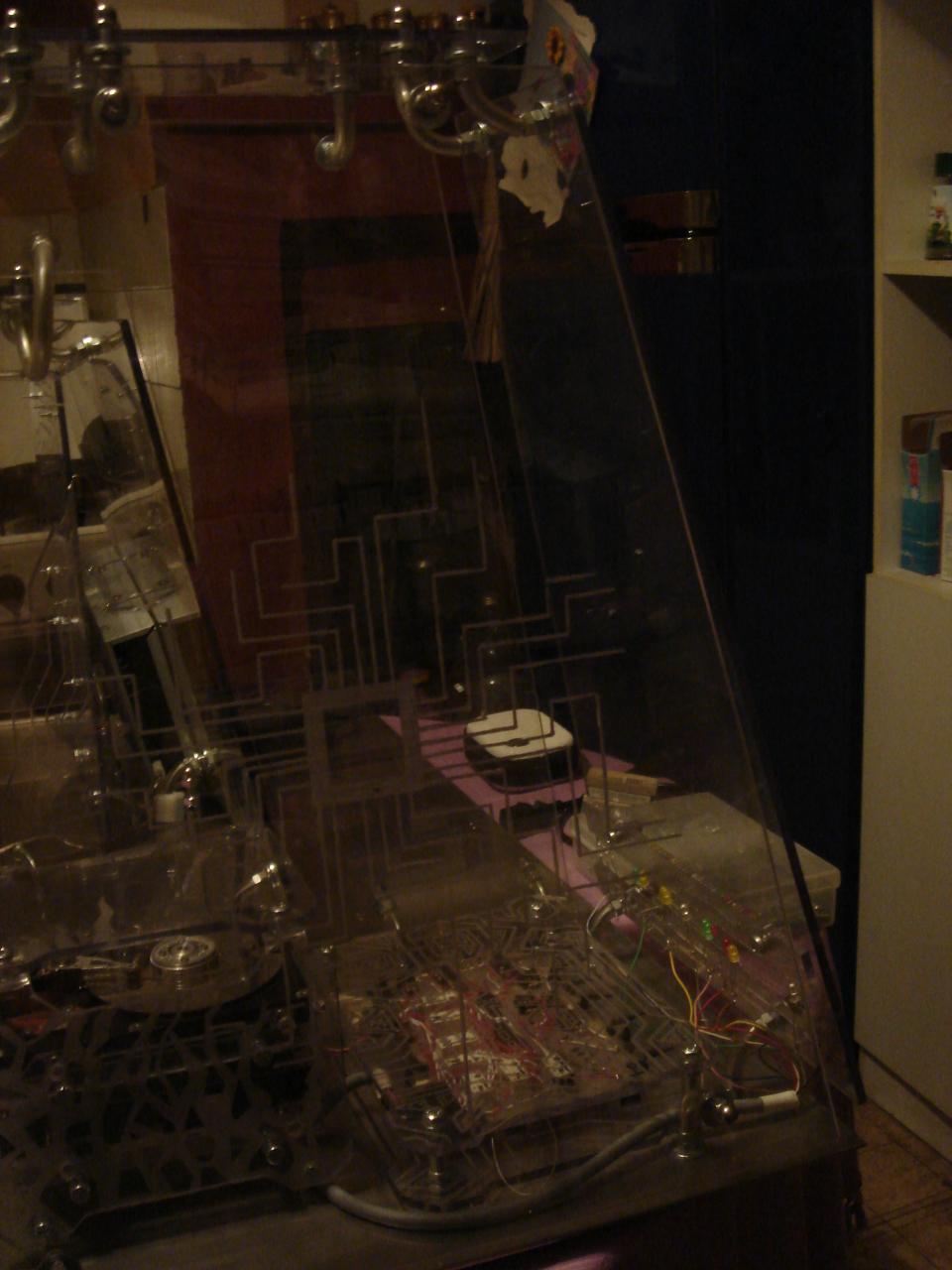
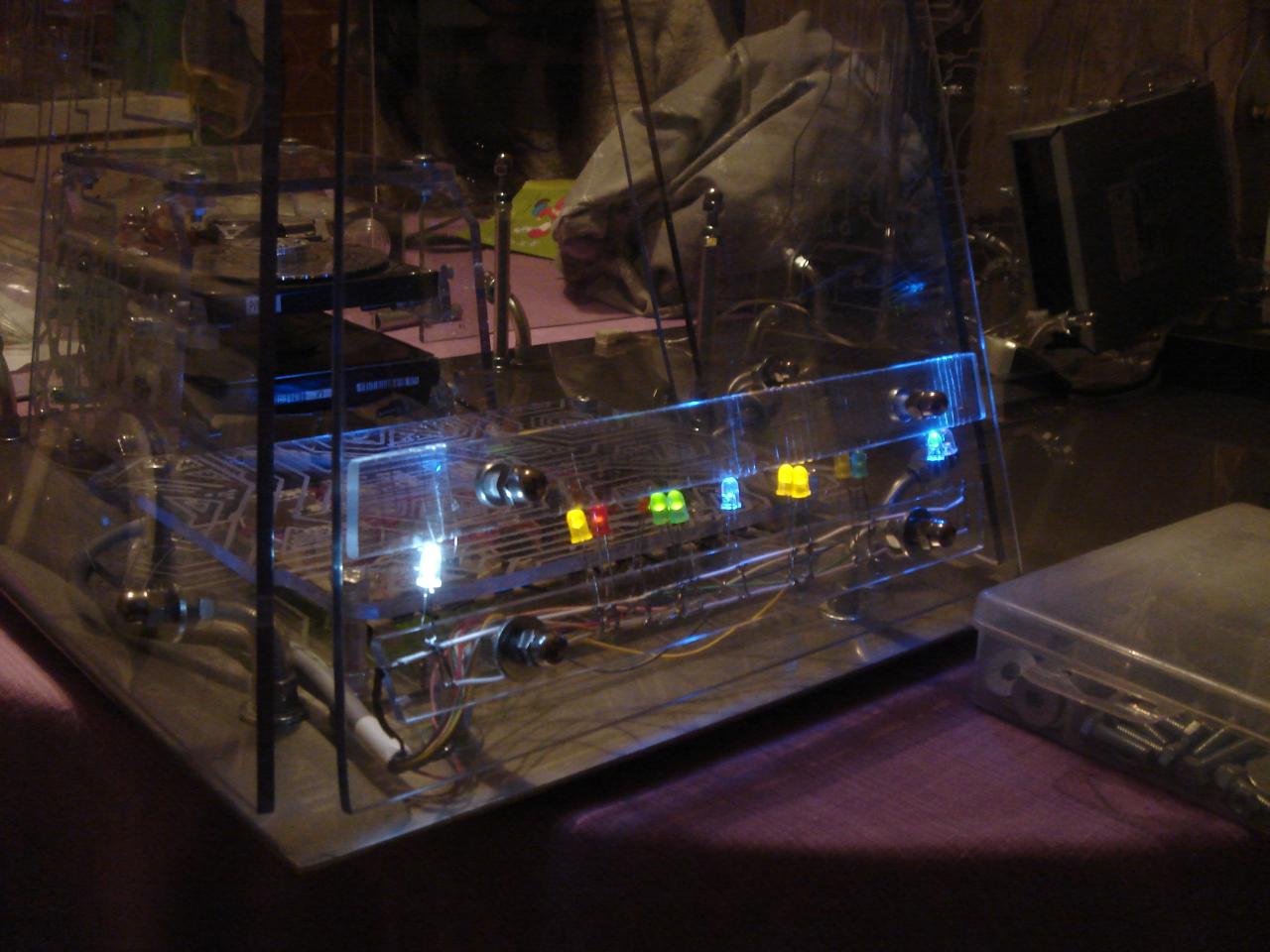
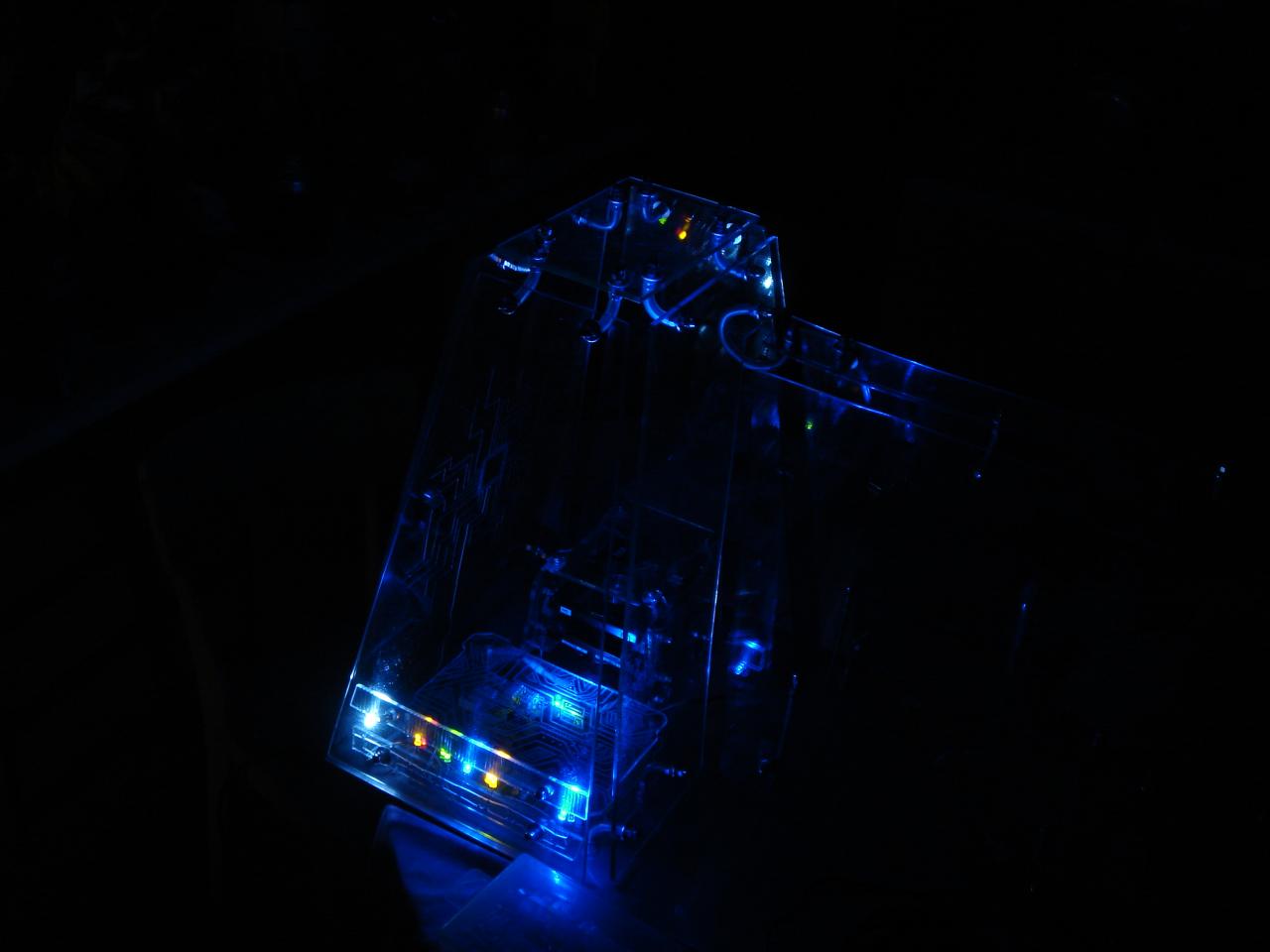
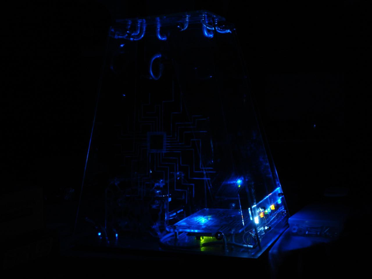
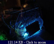
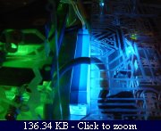
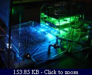
Some lighting tests:

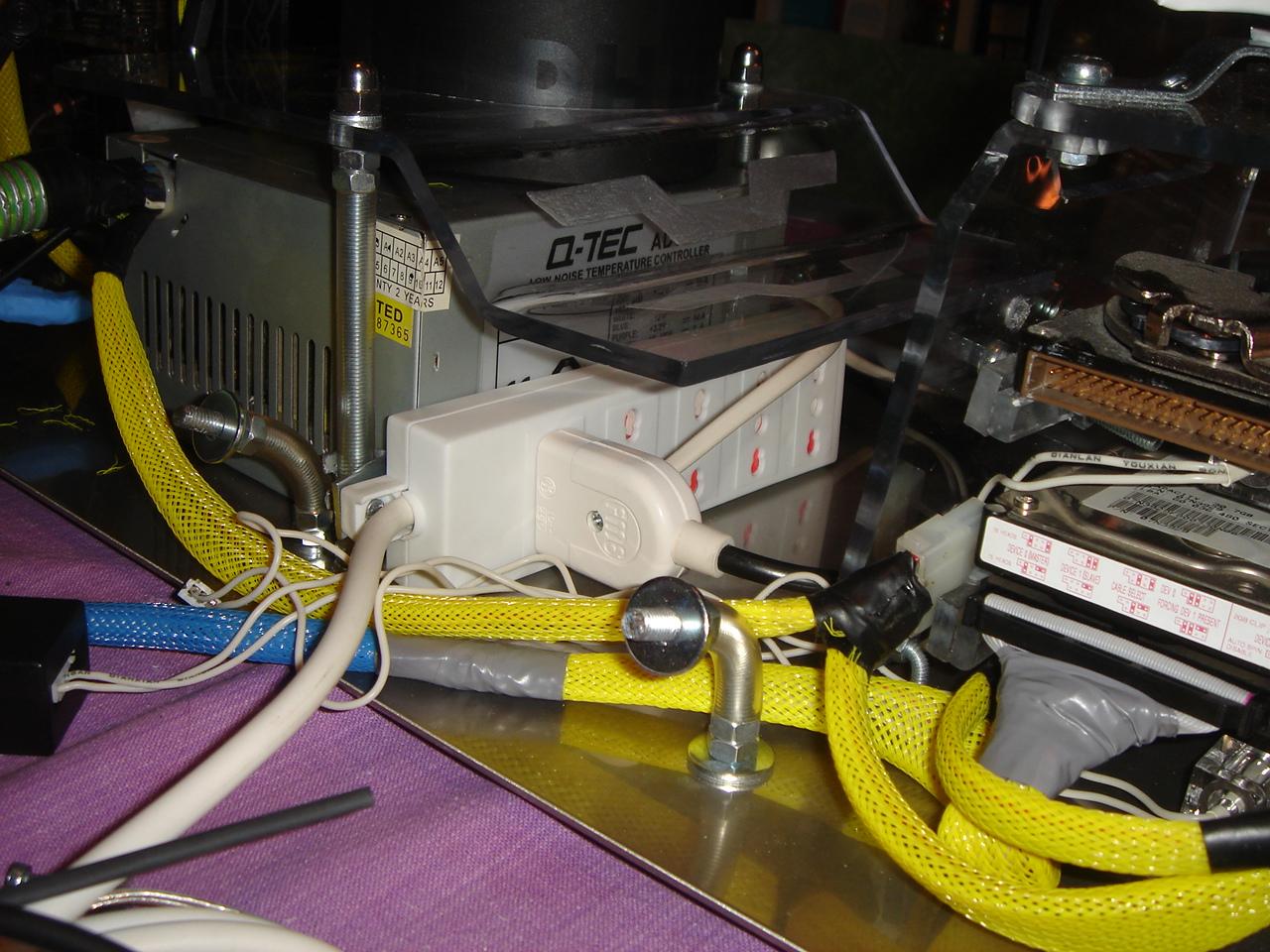
Here I mount a power strip too: (in the case are needed 4 sockets: PC, monitor, touch sensors circuit, videoprojector)

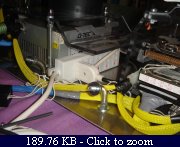
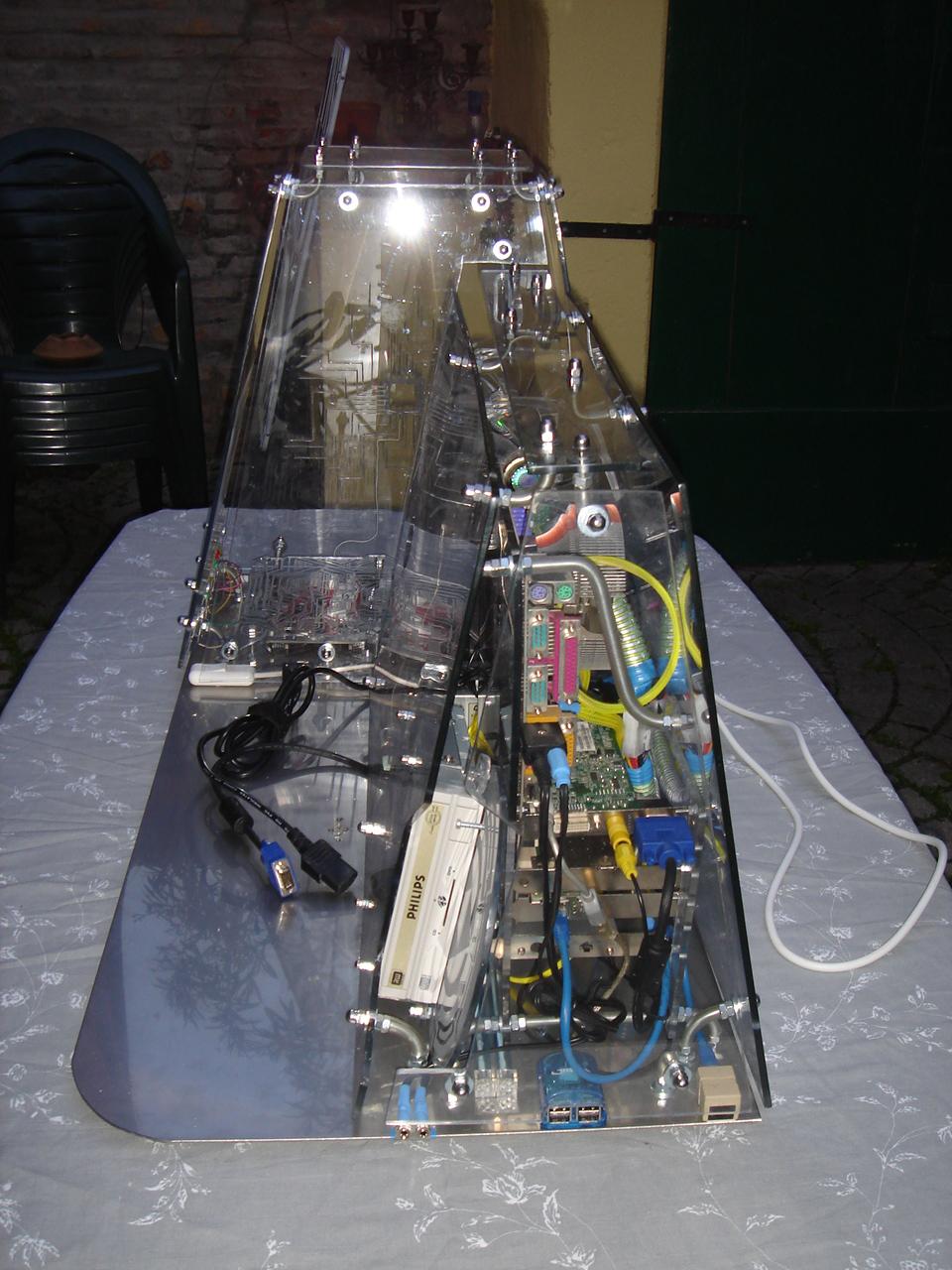
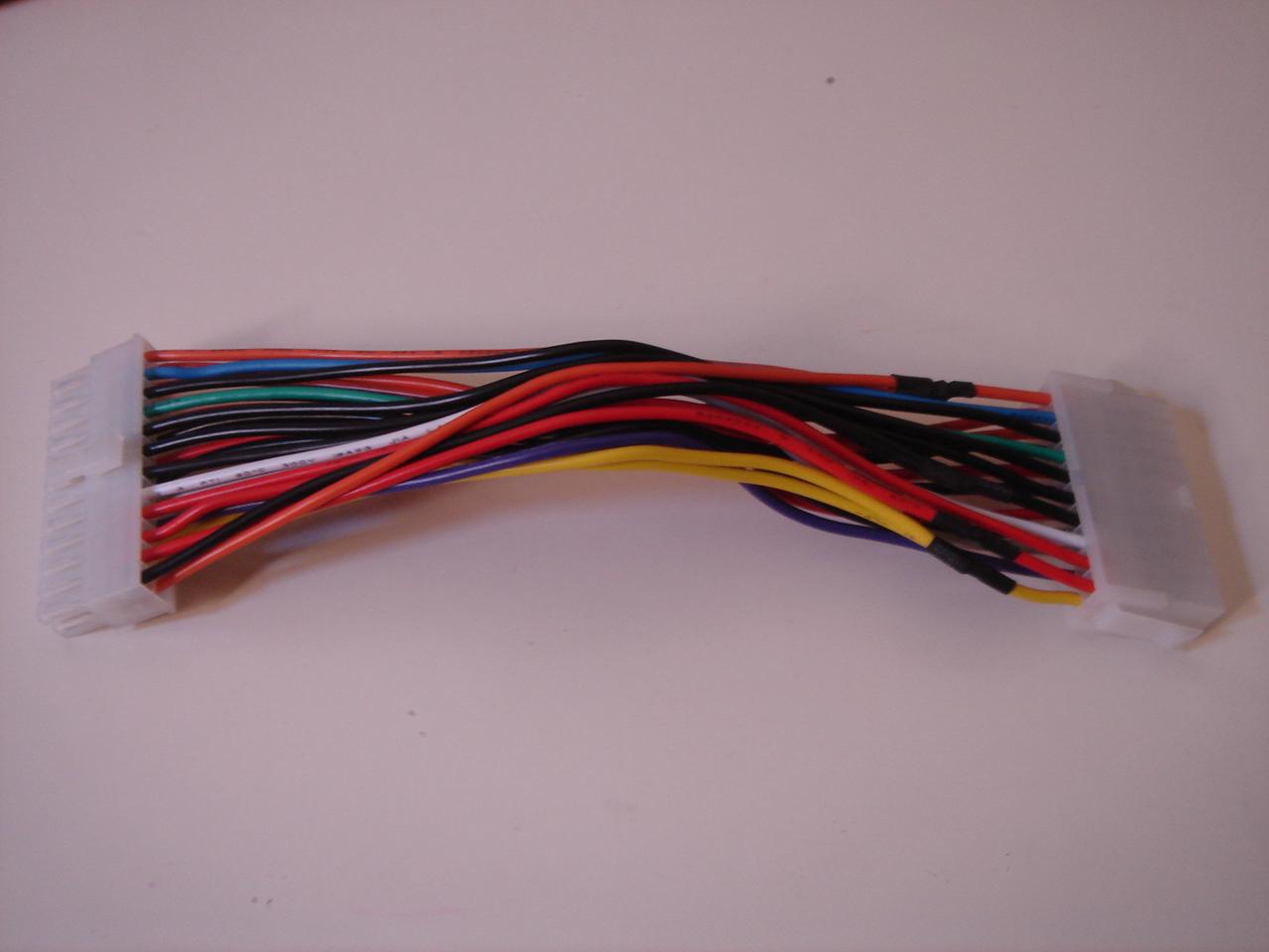
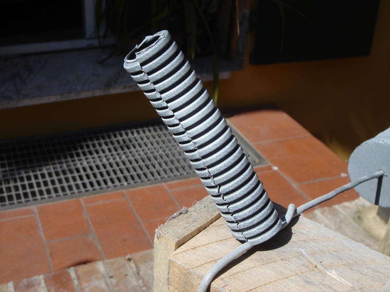
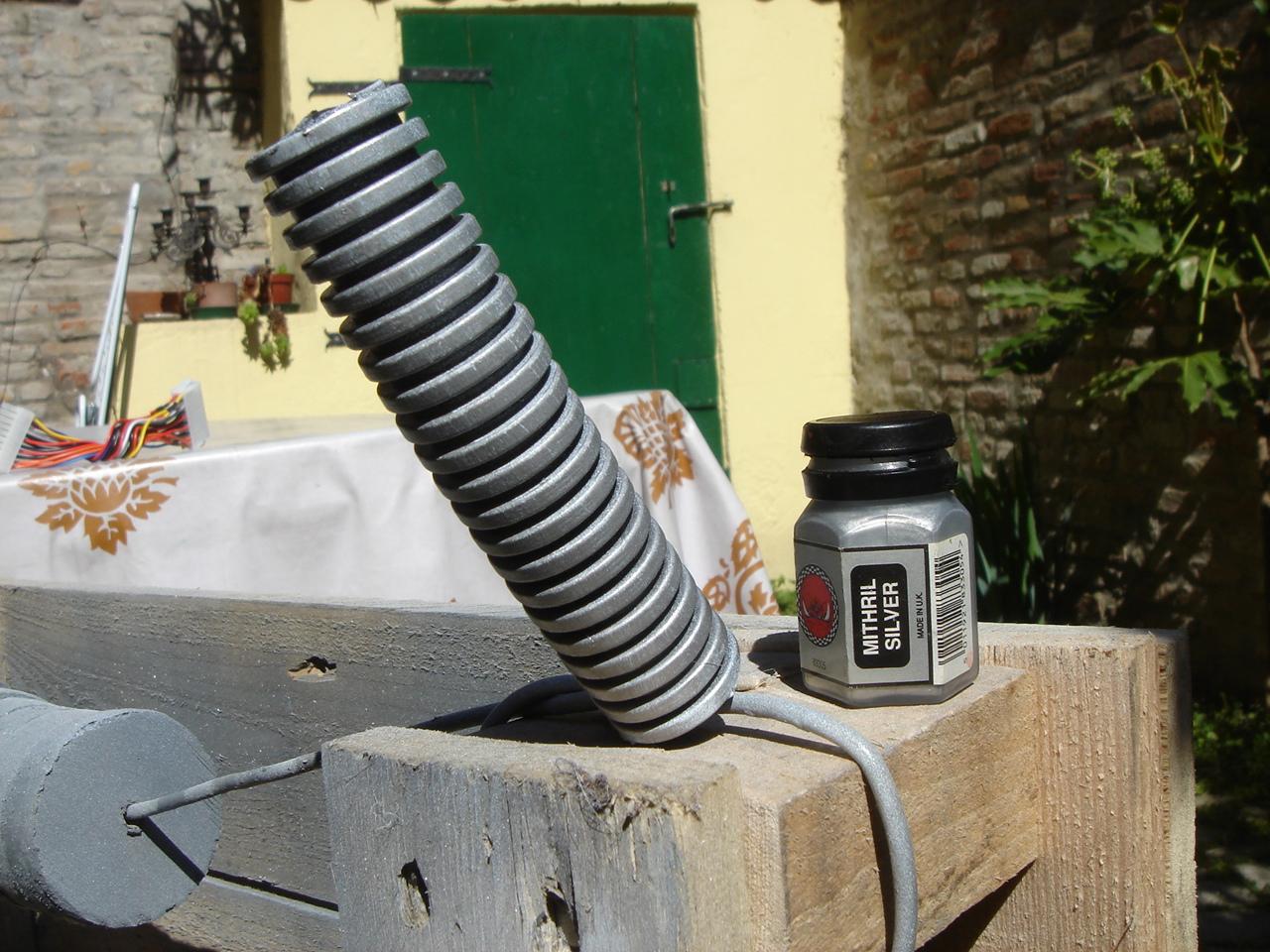
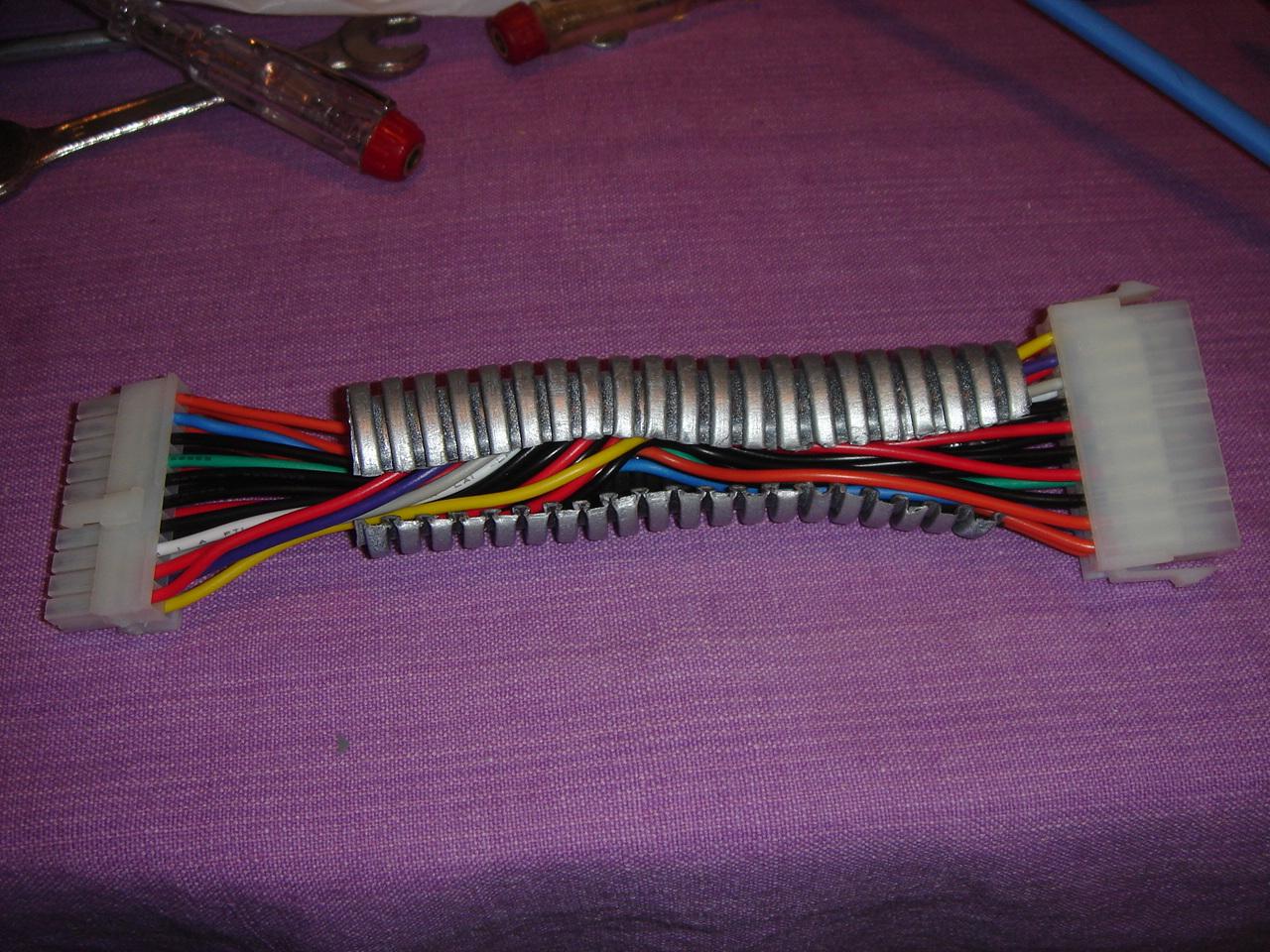
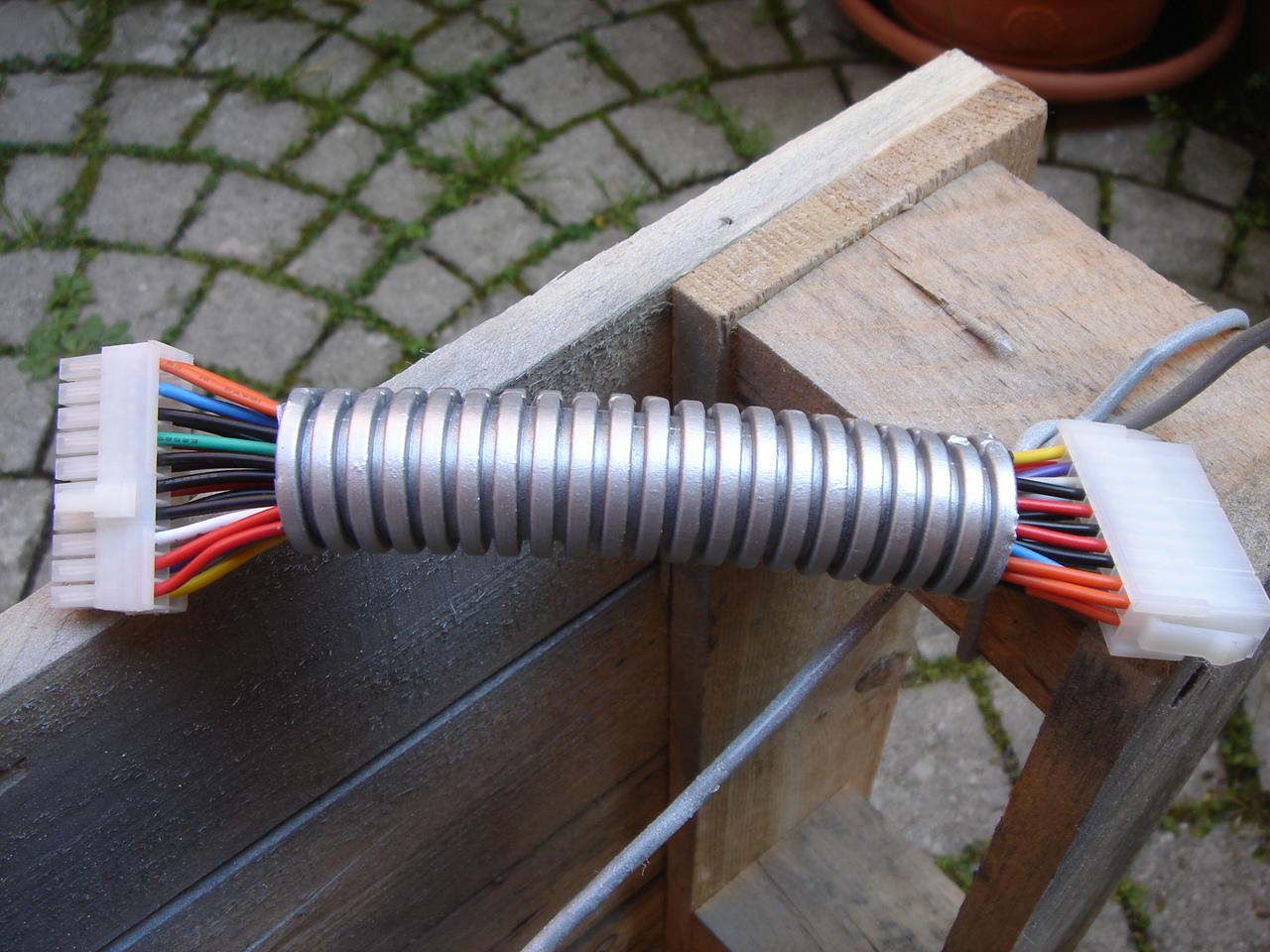
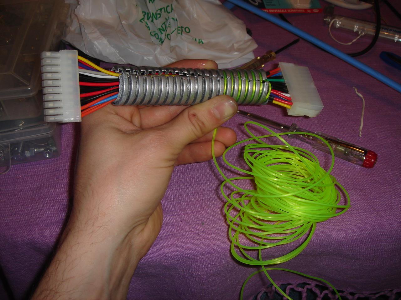
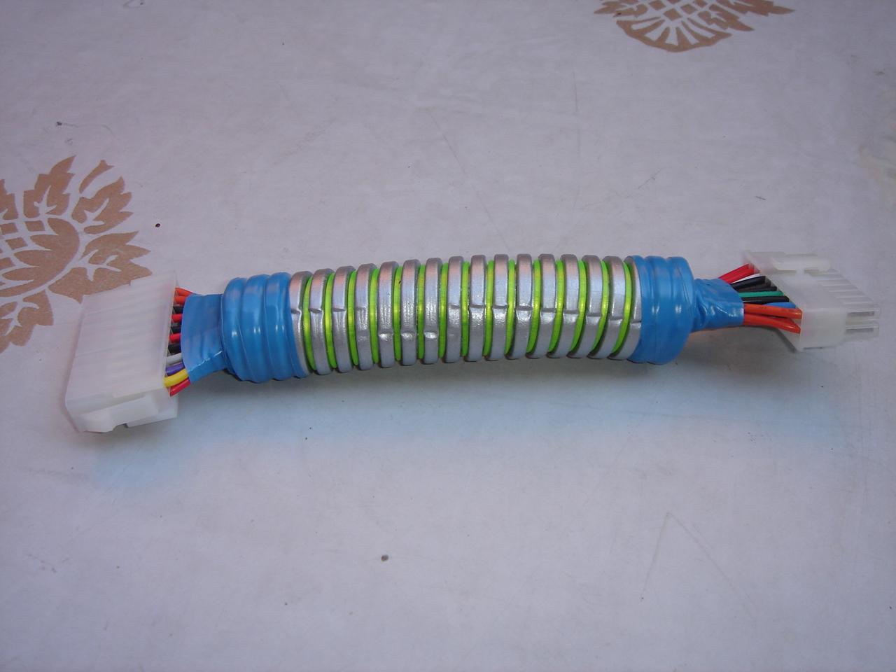
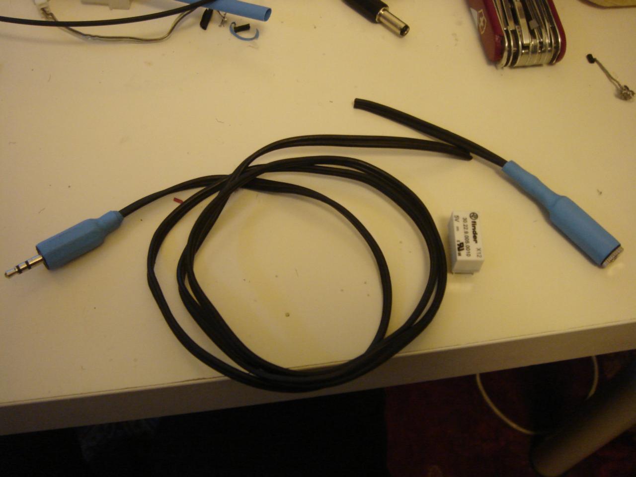
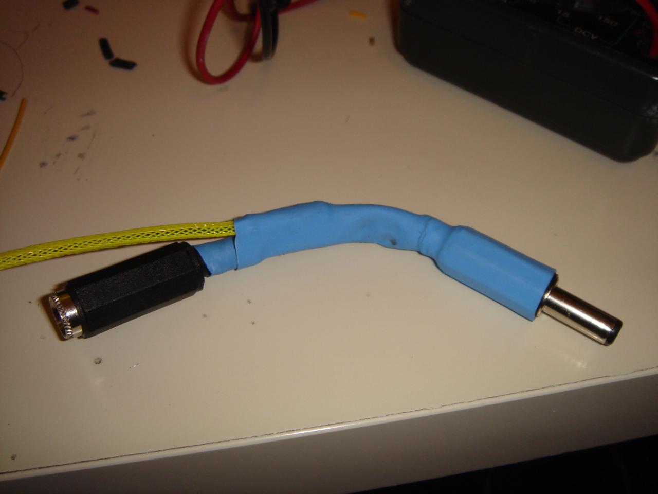
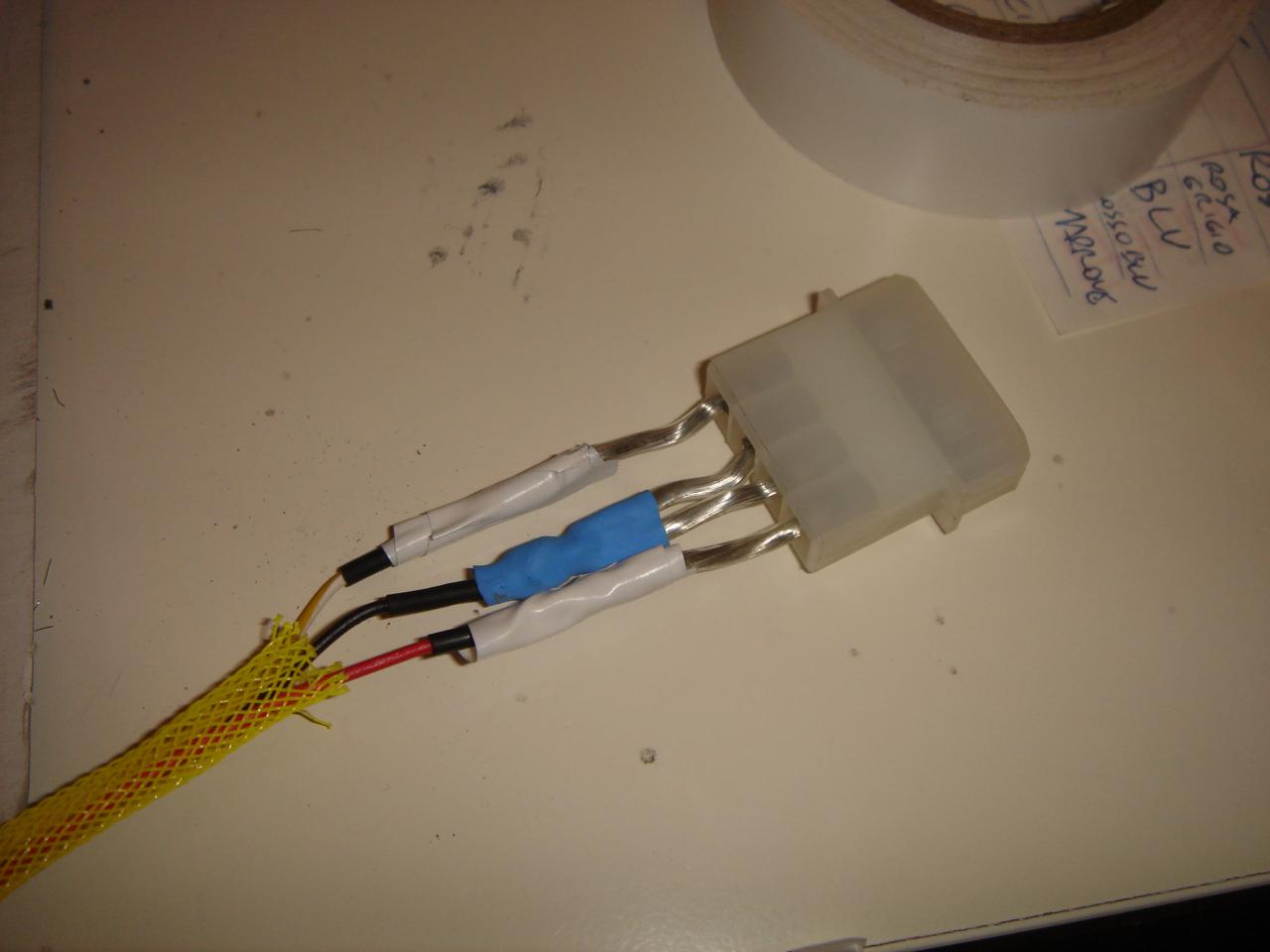
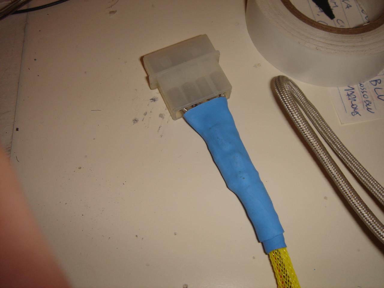
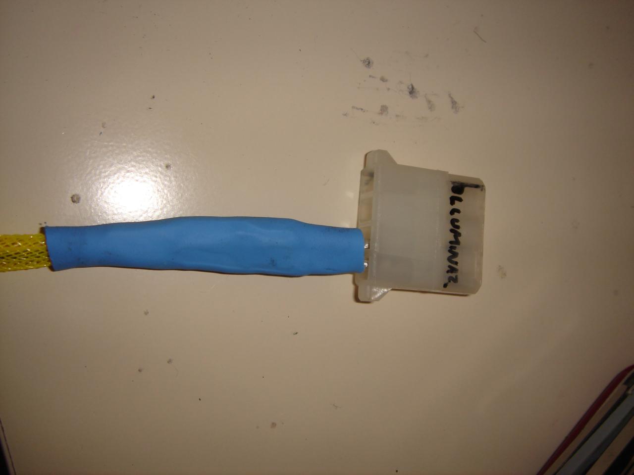
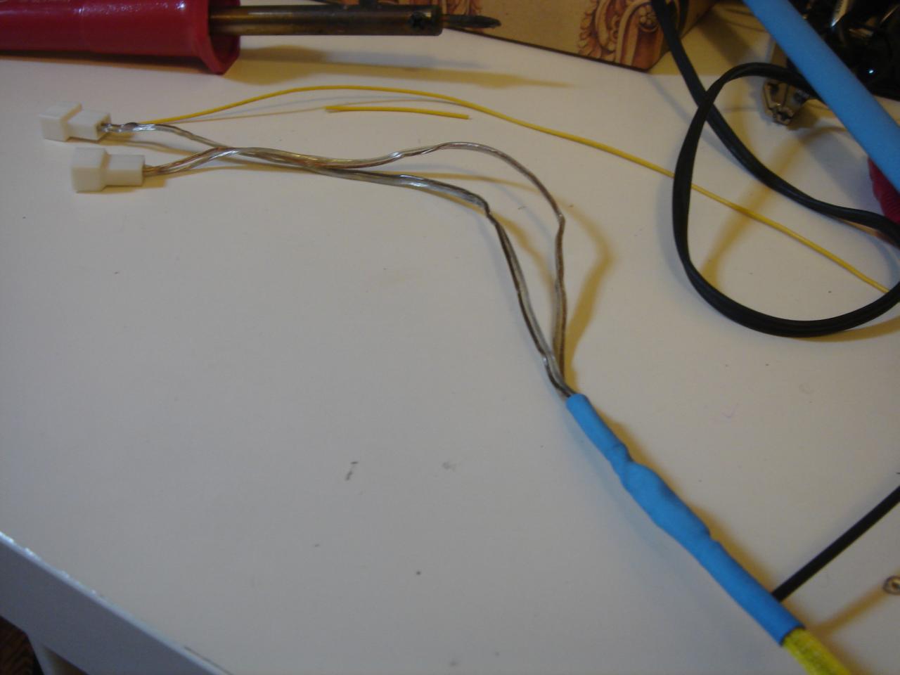
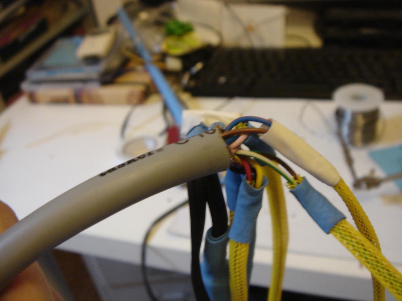
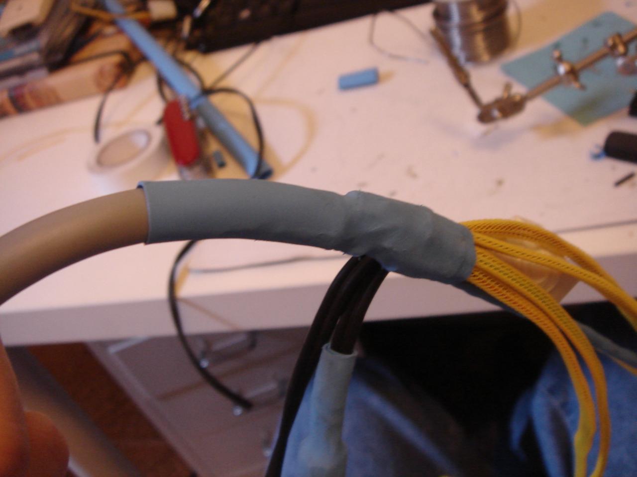
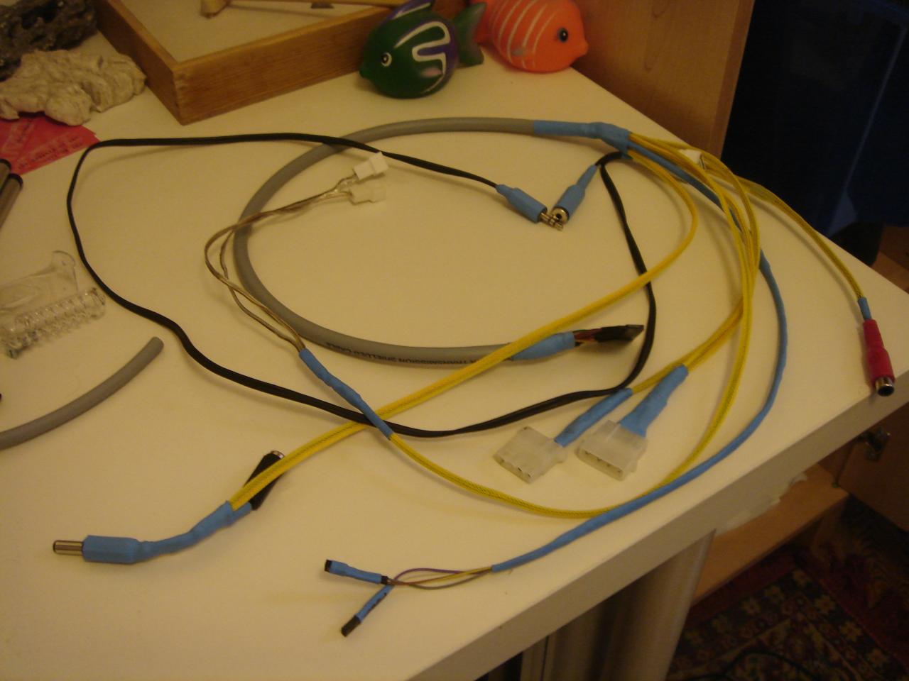
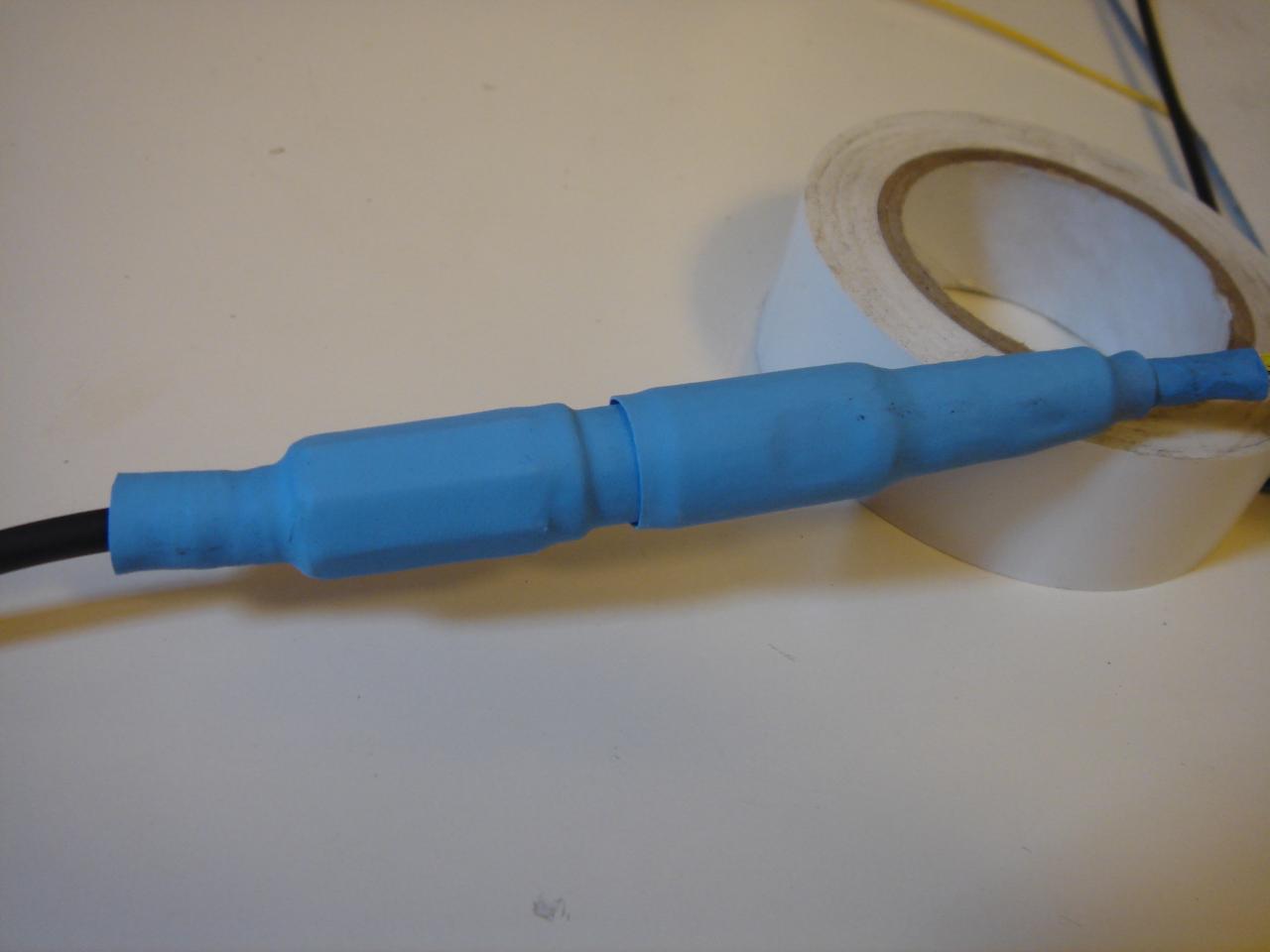
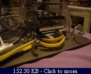
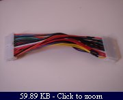
And this is the extension for the PSU-motherboard cable:
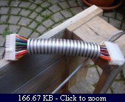
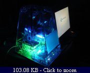
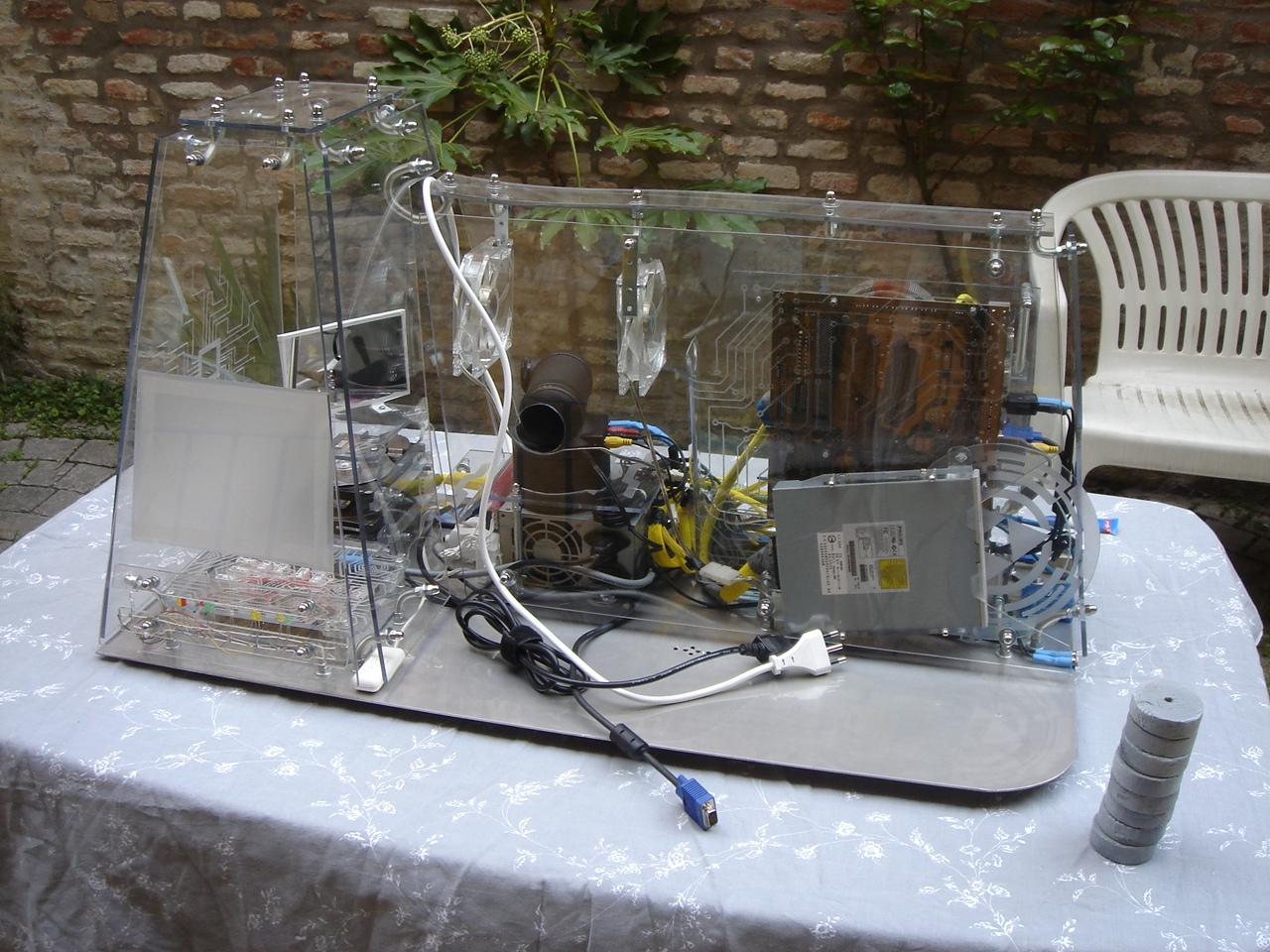
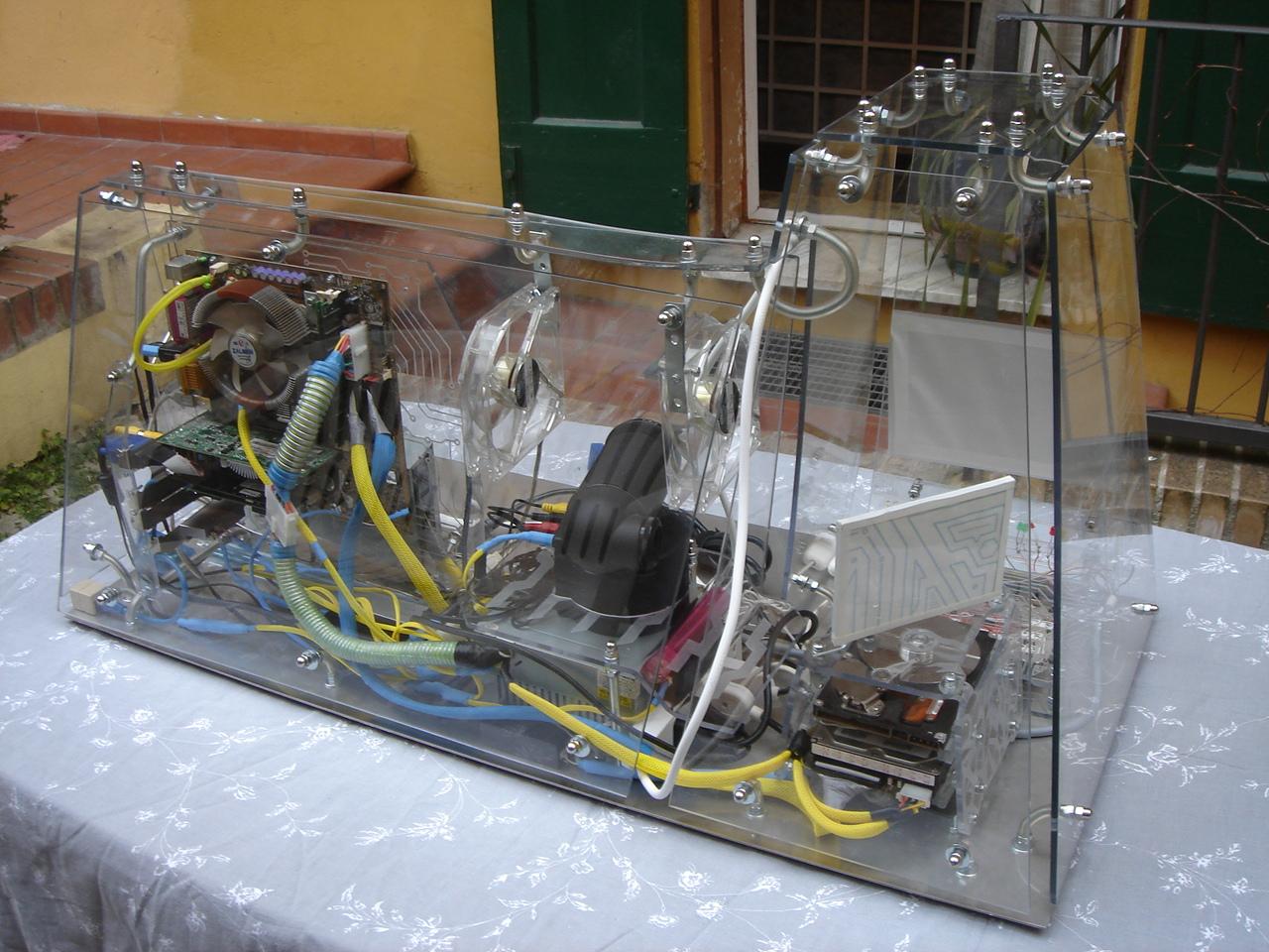
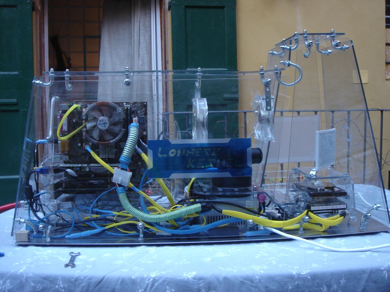
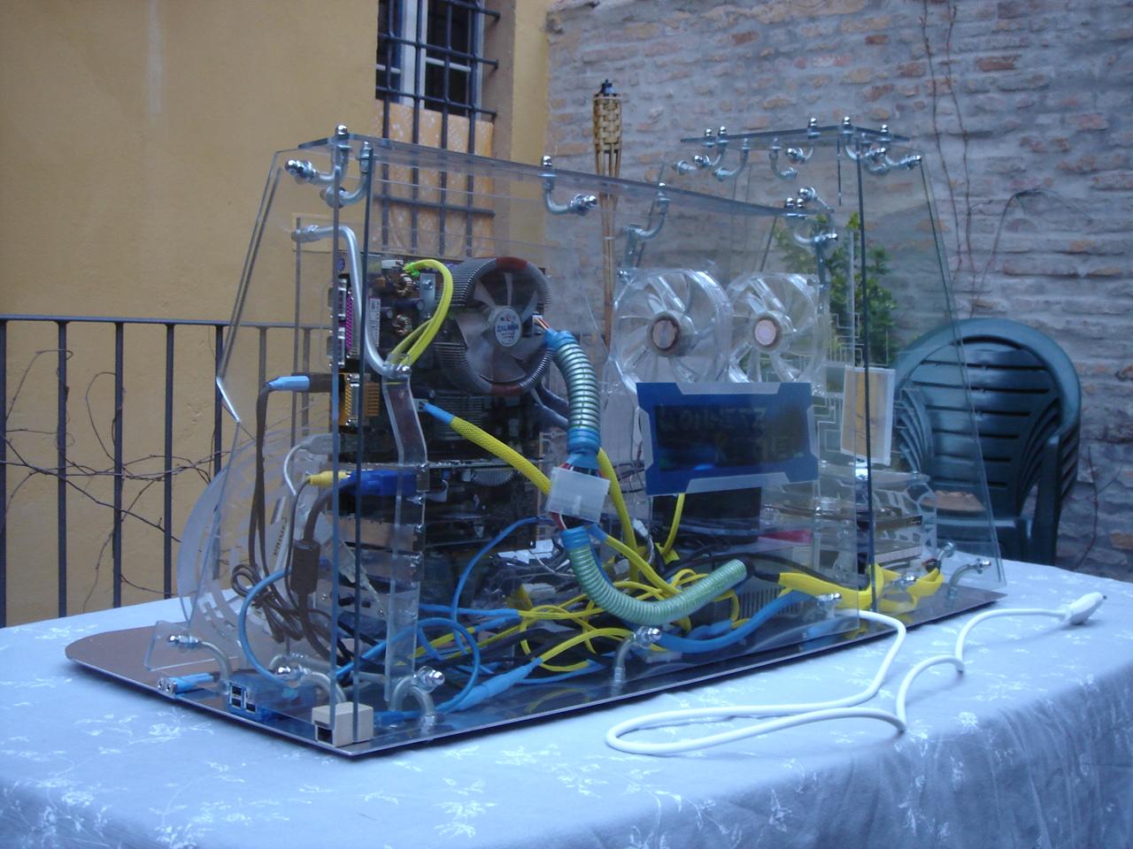
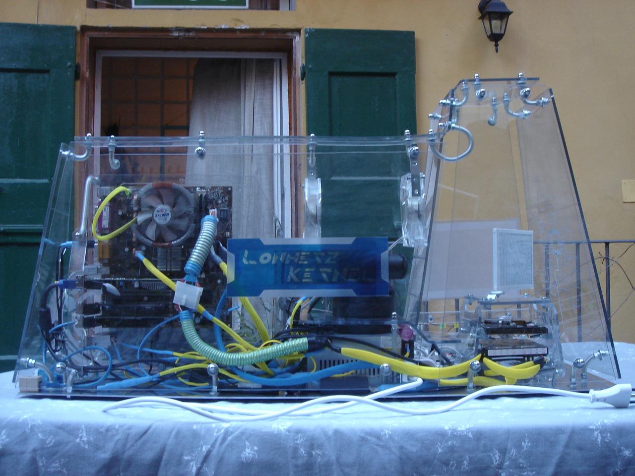
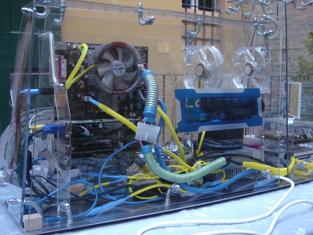
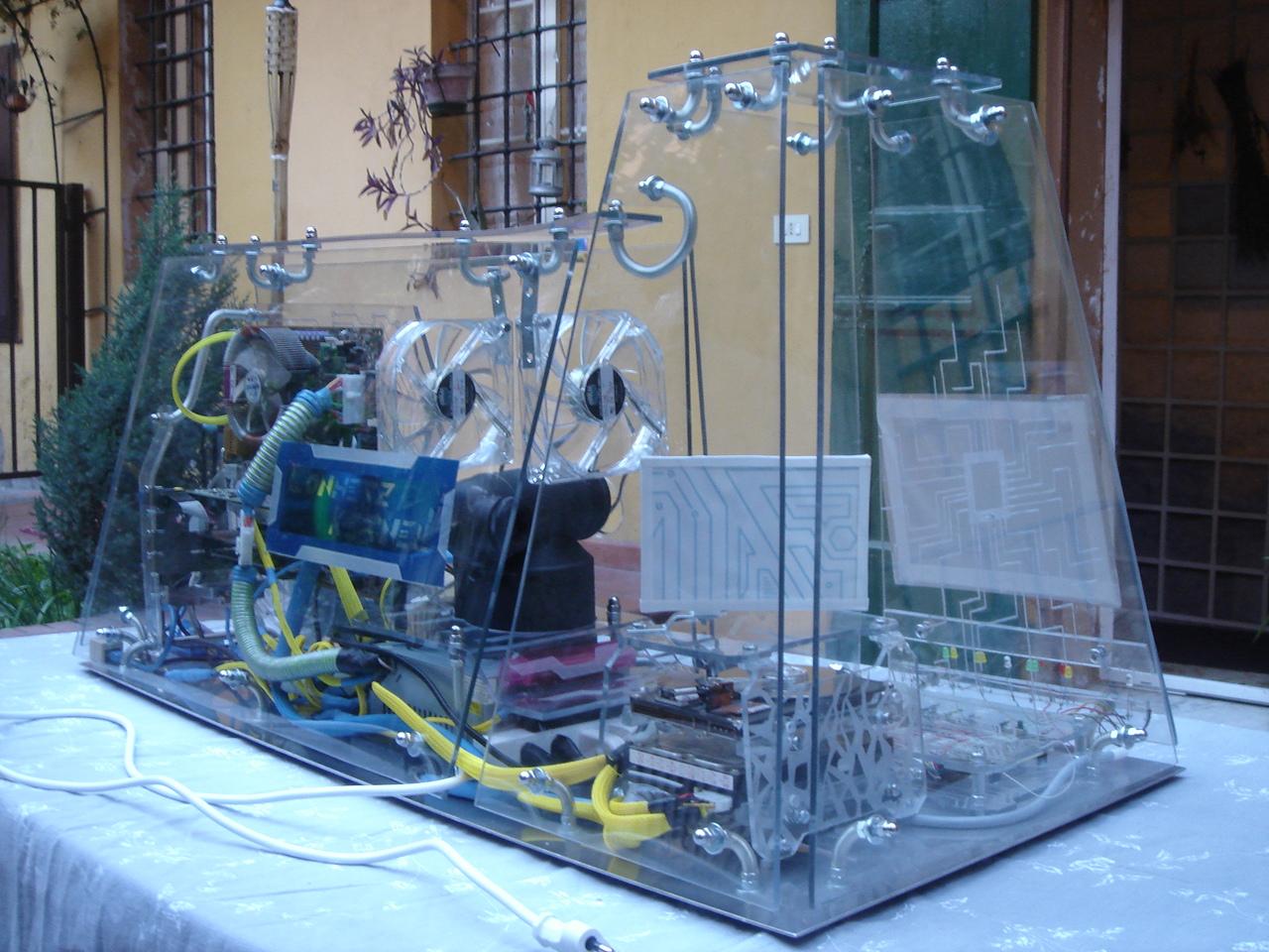
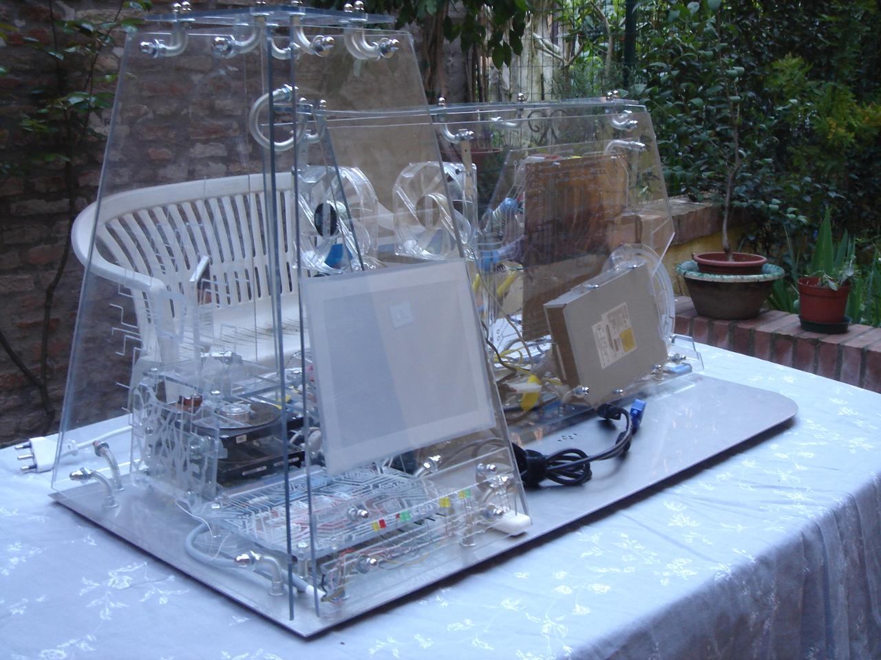
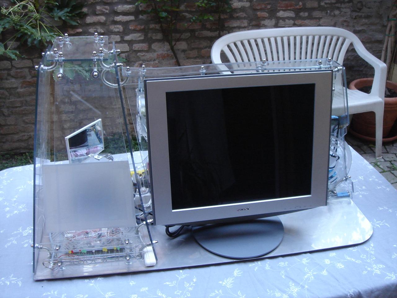
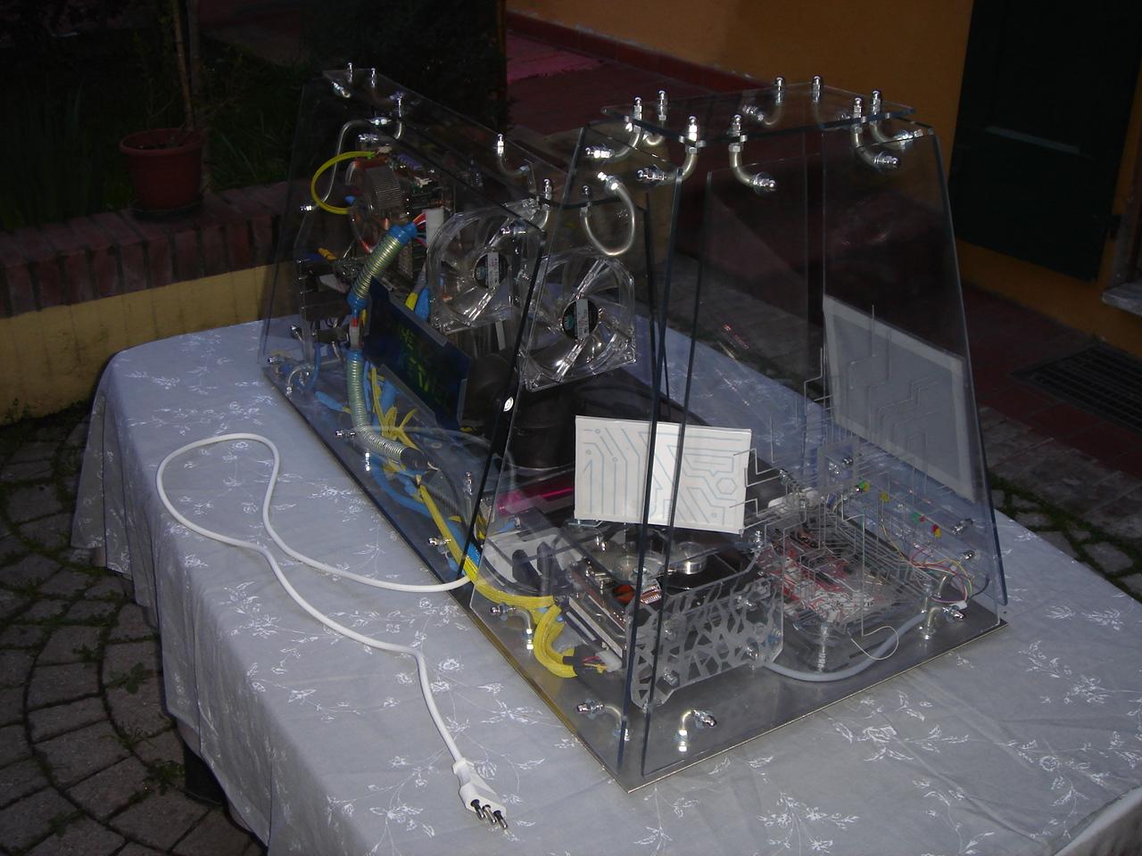
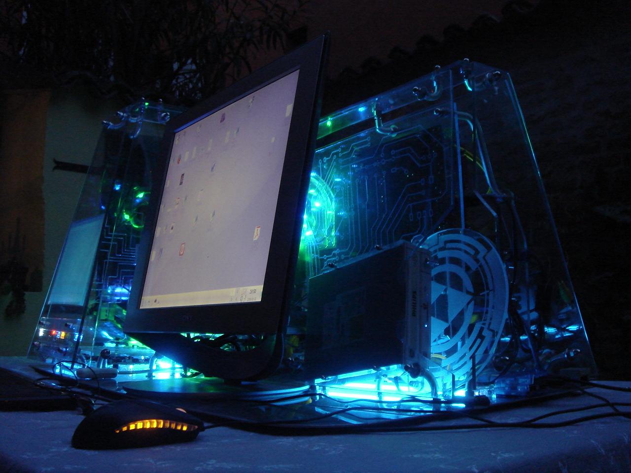
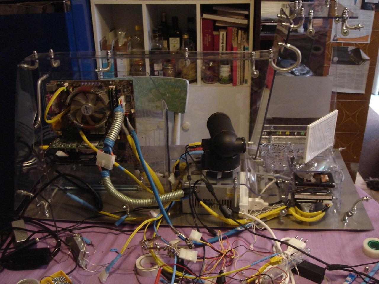
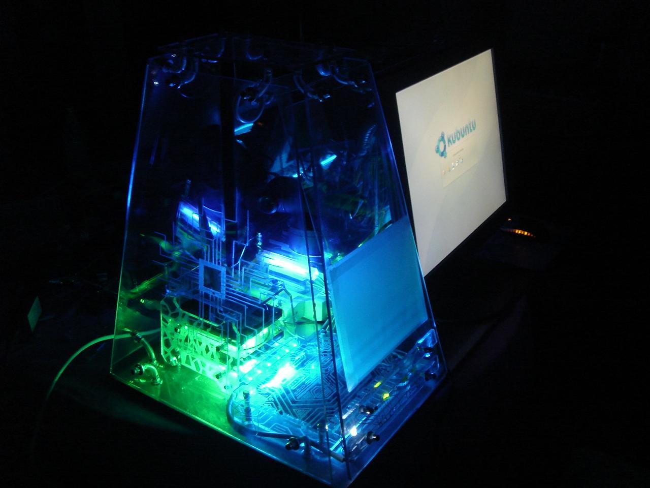
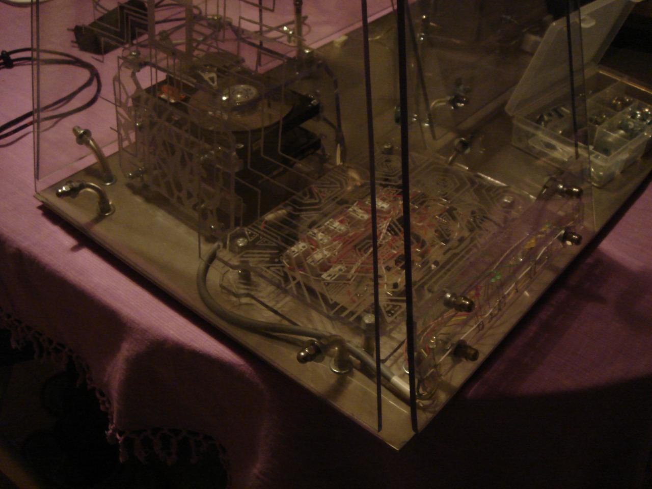
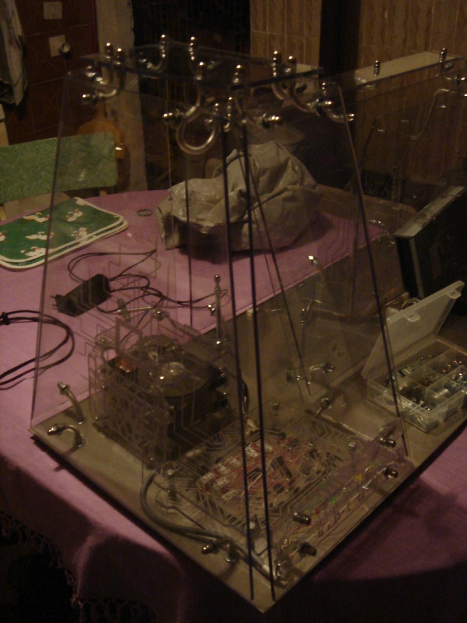
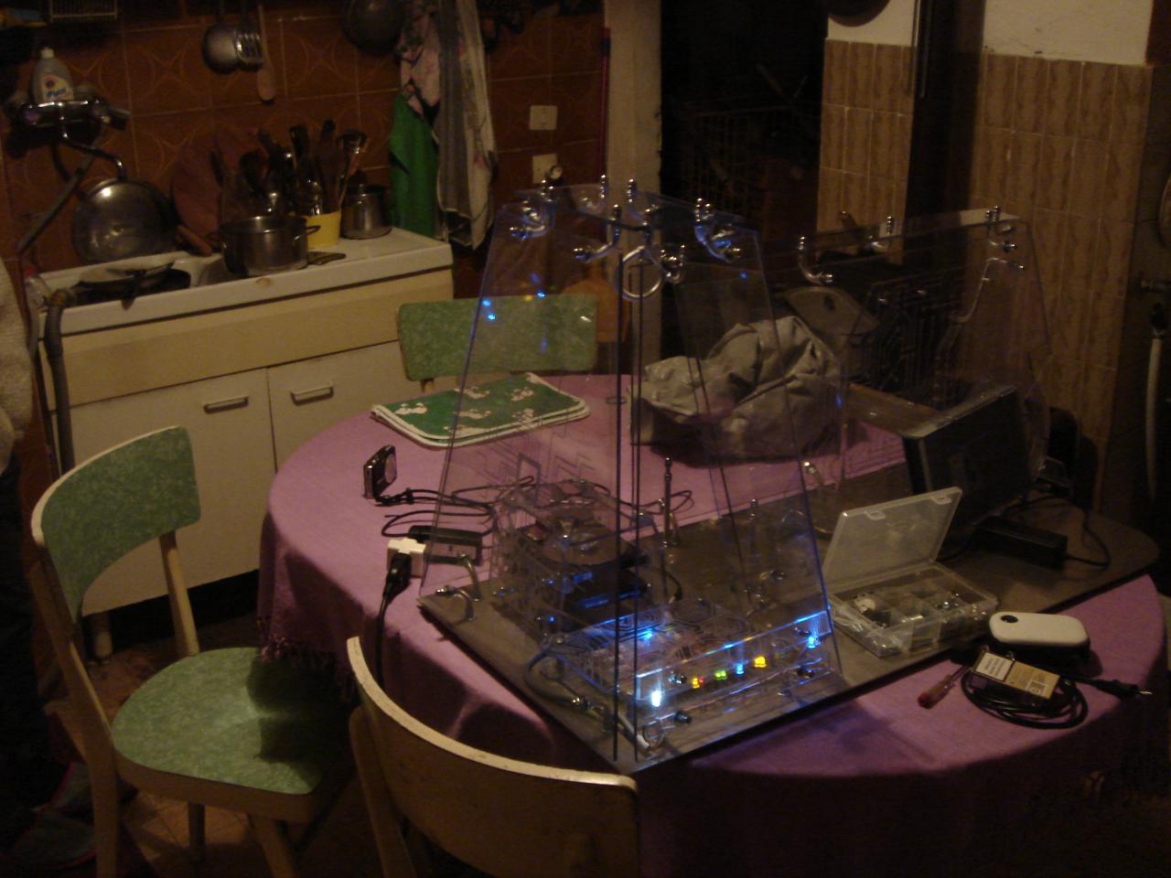
The final result:

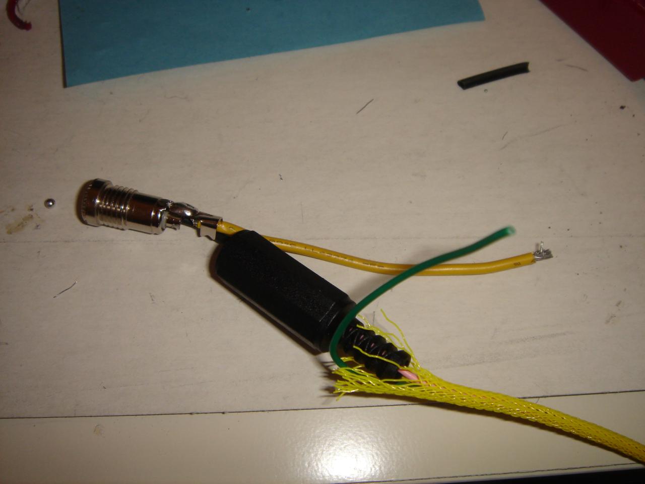
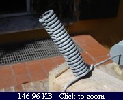
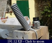
Then I had to extend the 4 pin PSU-CPU cable too:

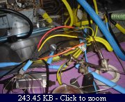
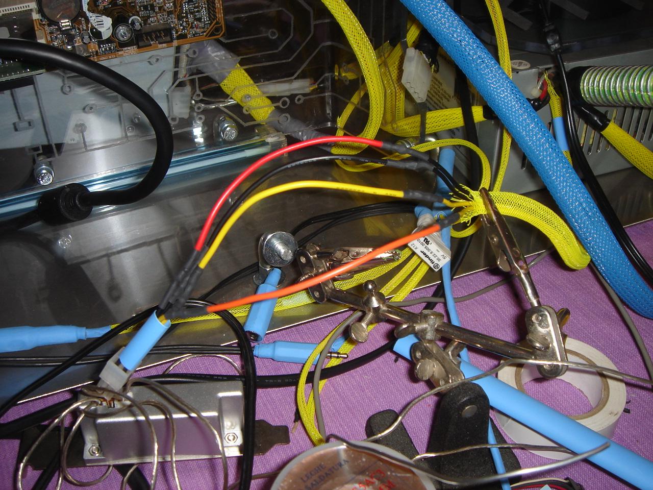
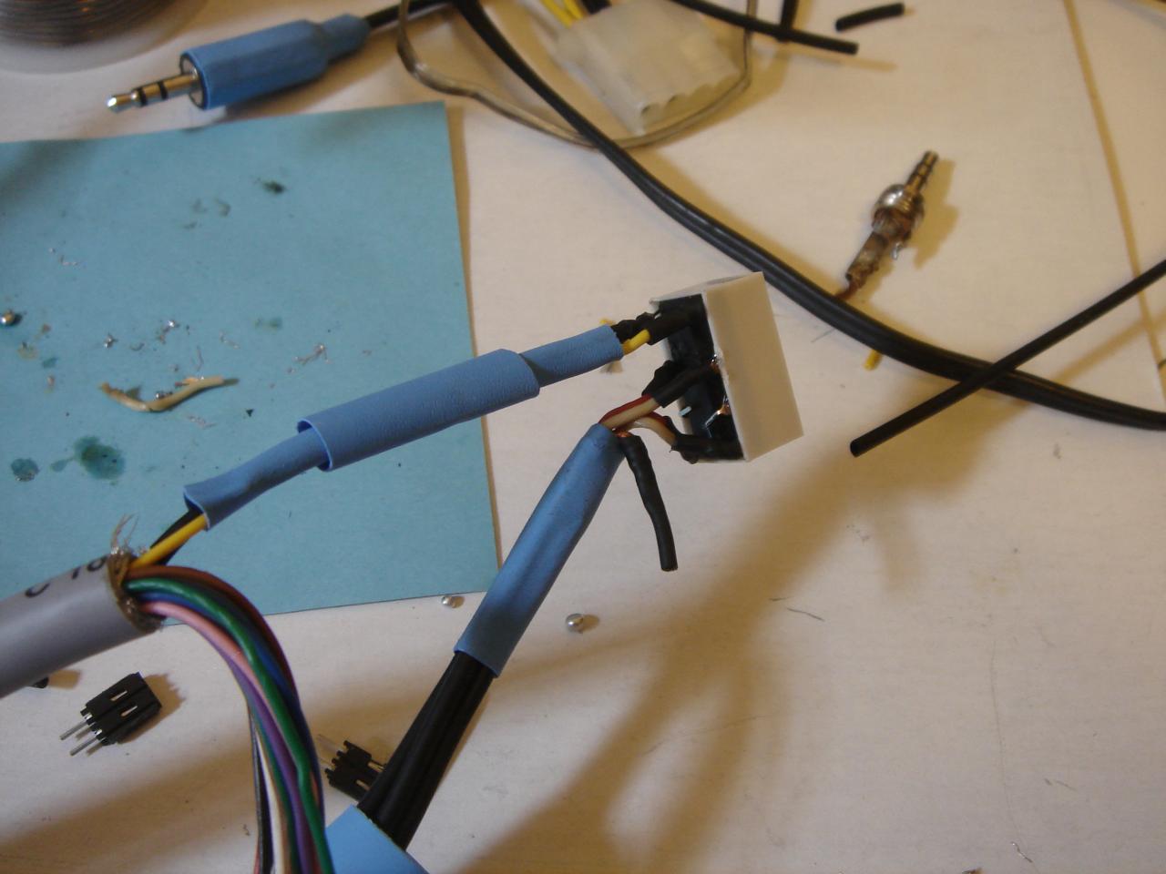
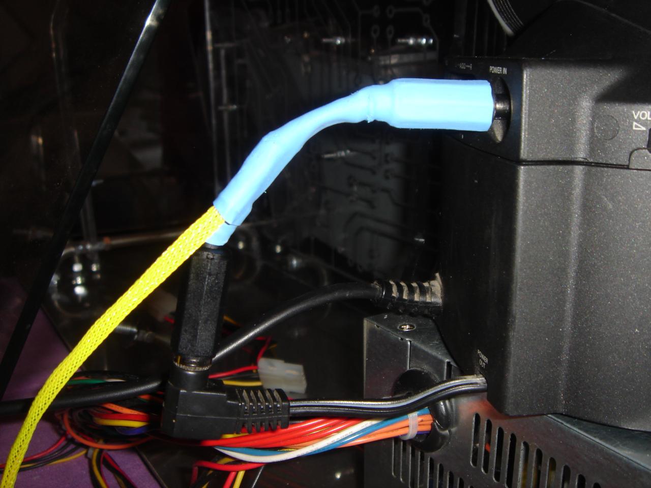
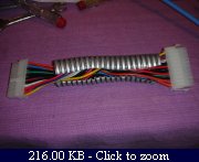
And these are the two extended cables connected to the motherboard:

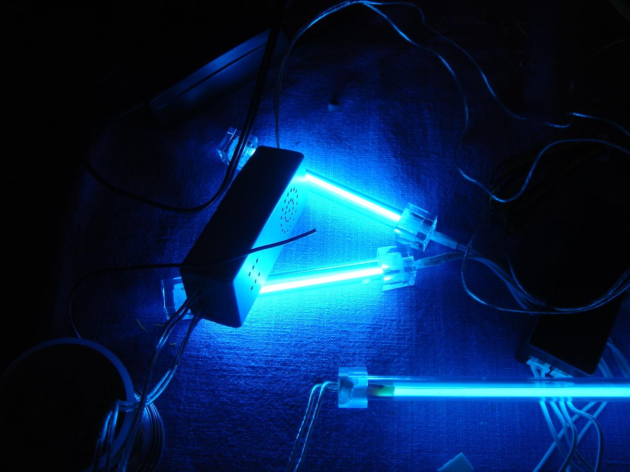
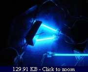
Some other cold cathode lights:

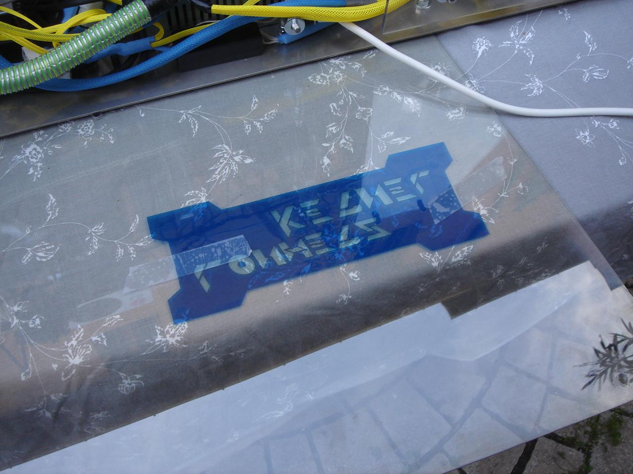
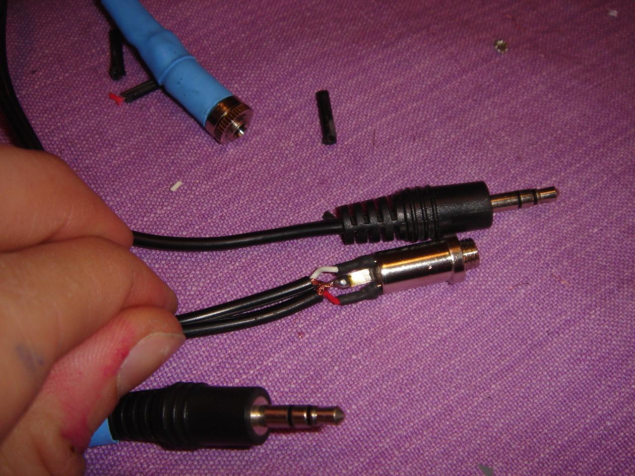
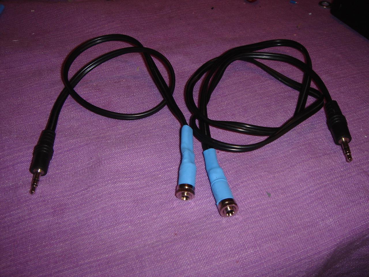
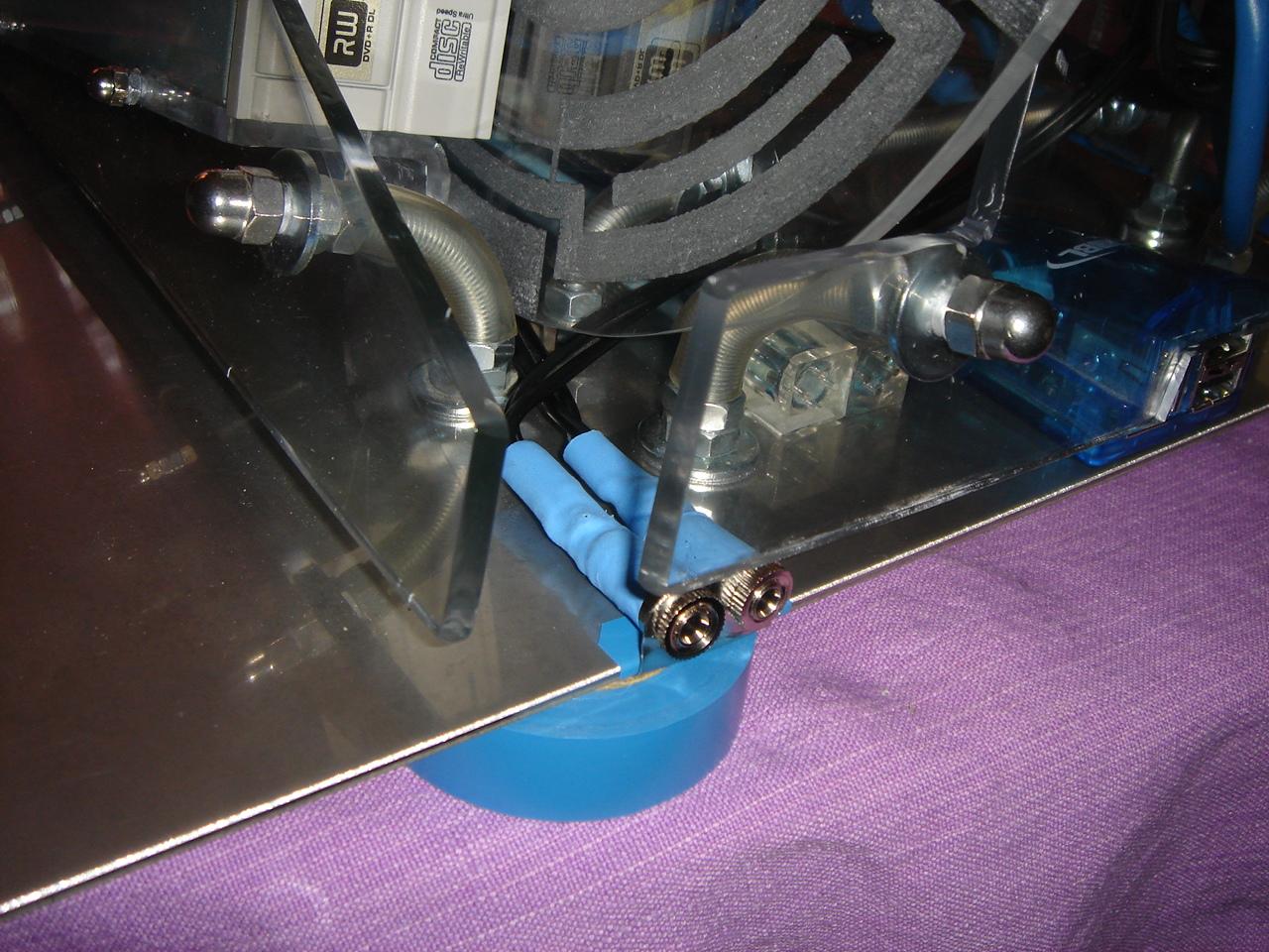
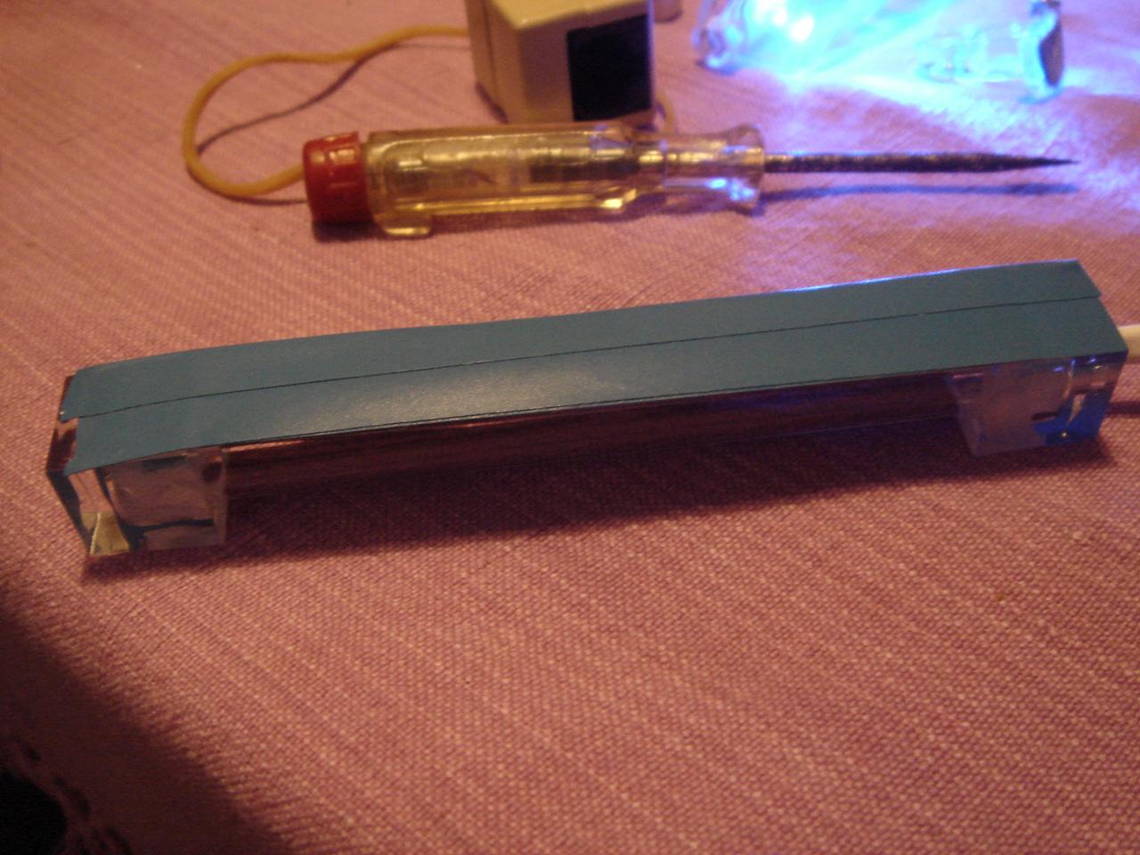
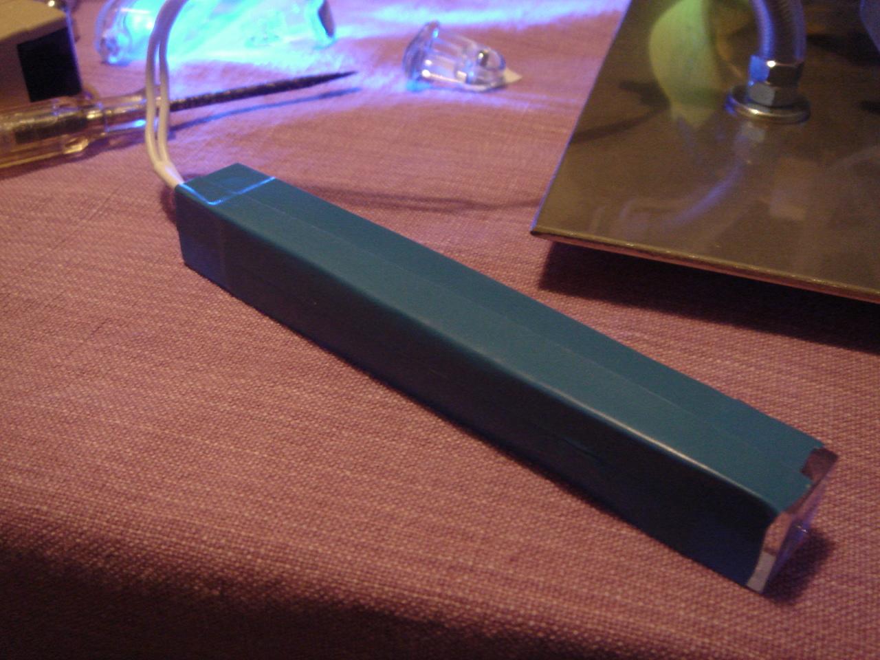
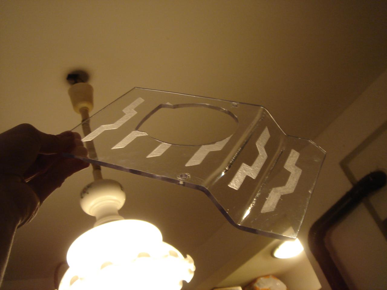
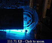
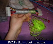
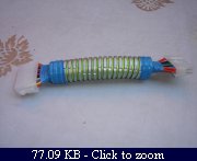
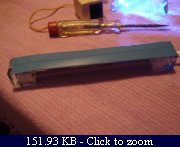
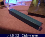
To avoid lighting the green infected sector with blue light, for the circuit encasing I have covered with some blue tape 3 of 4 sides of the cold cathode tube:

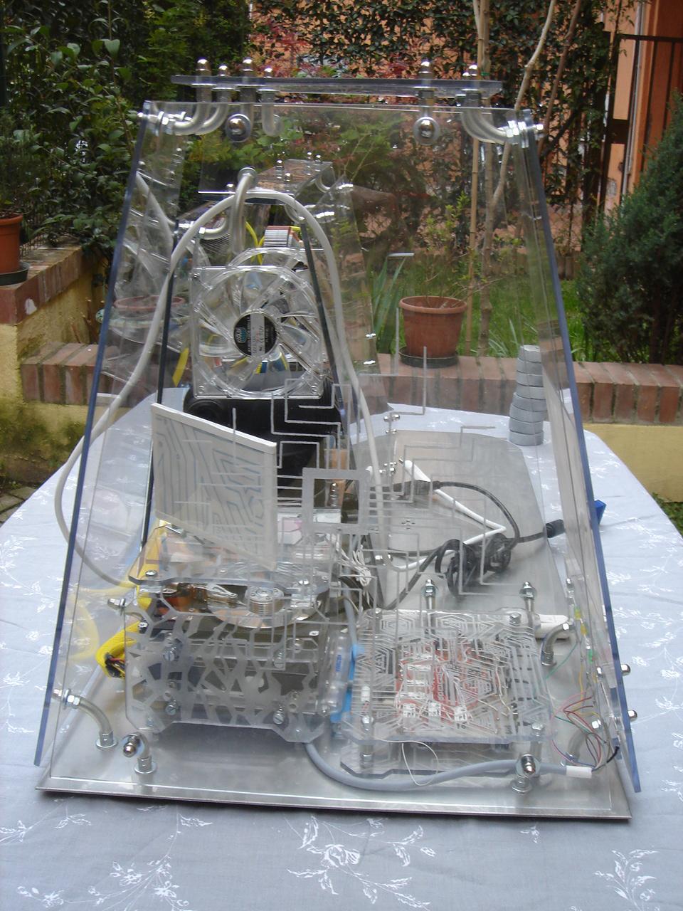
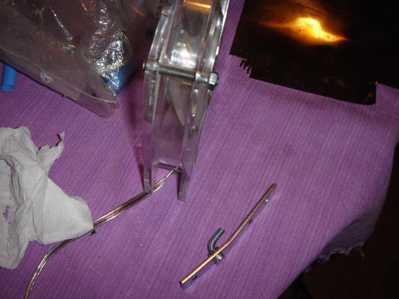
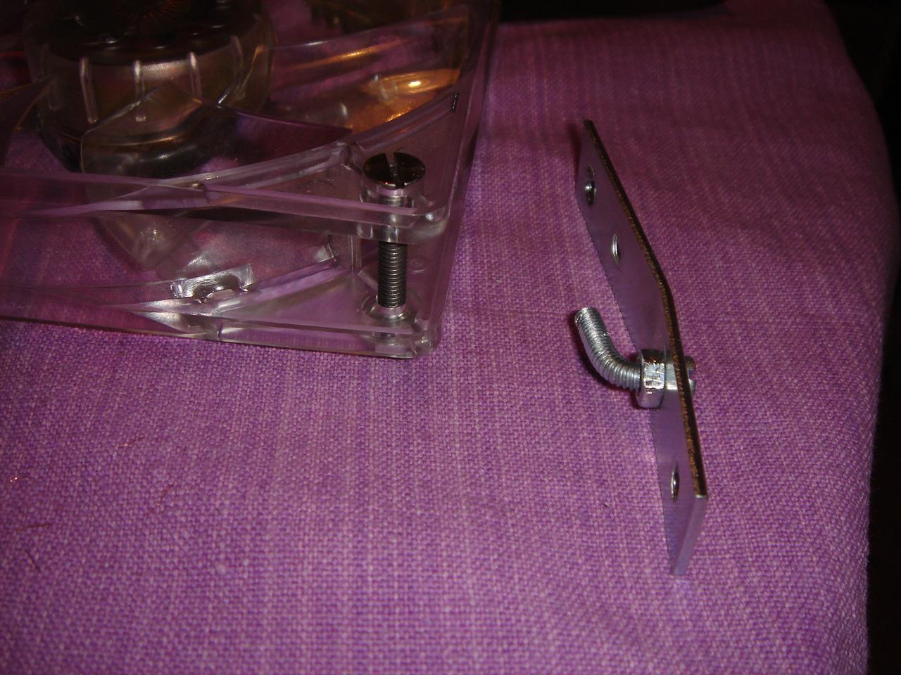
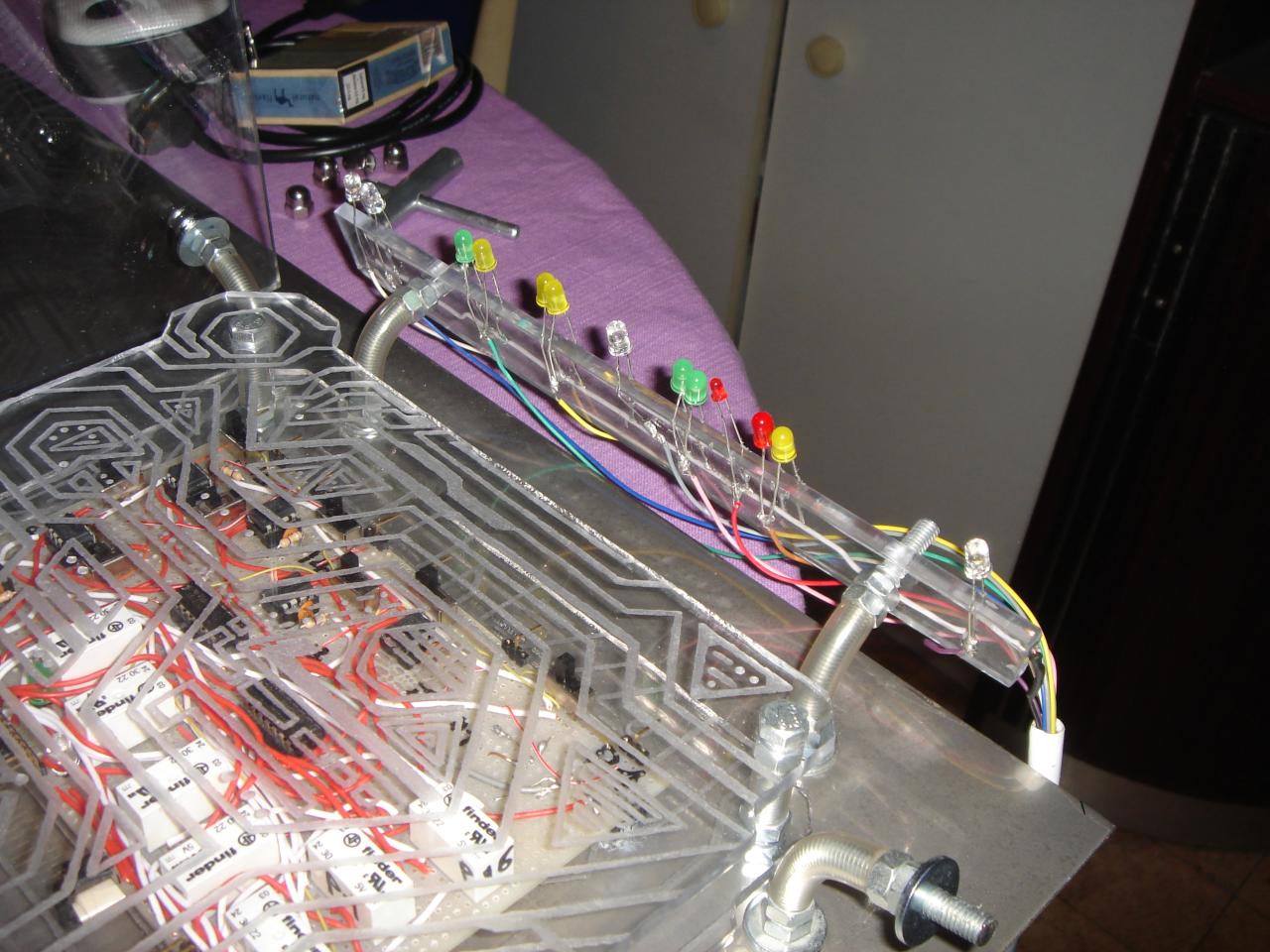
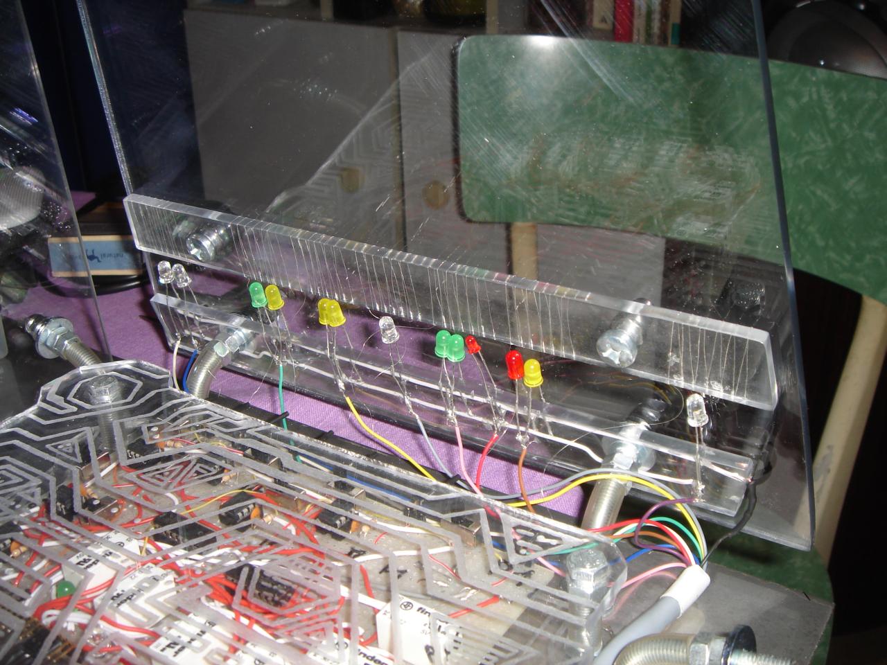
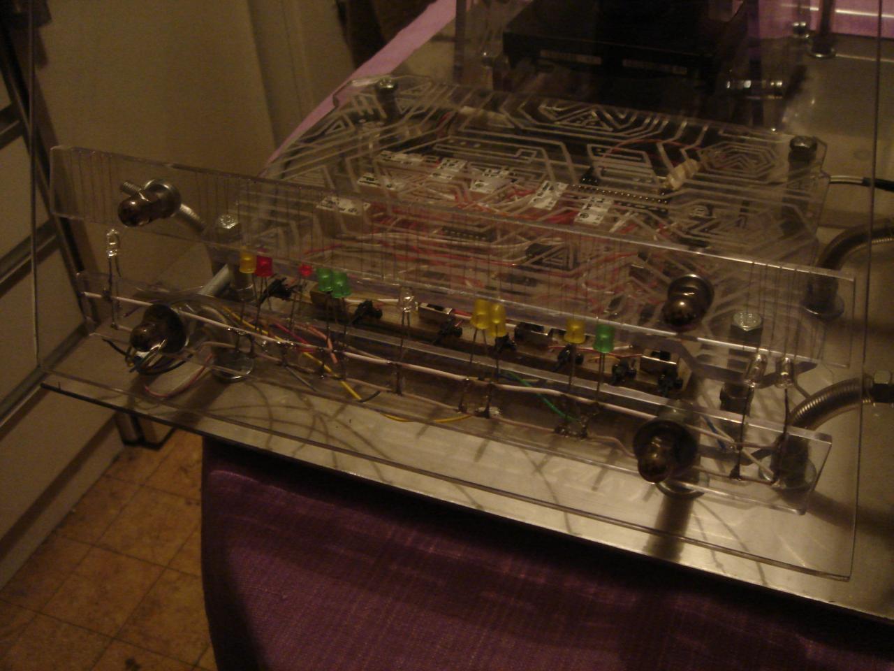
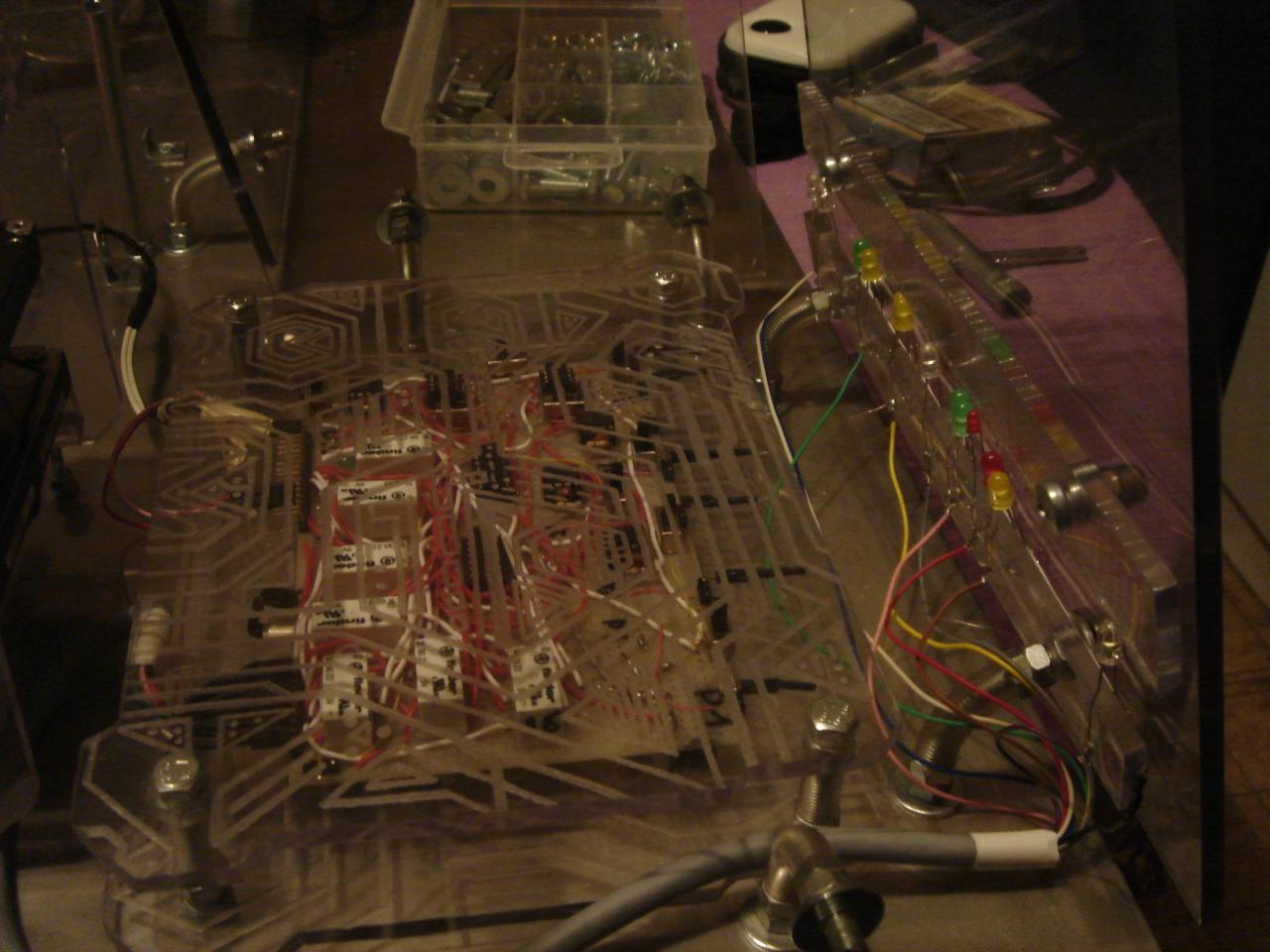
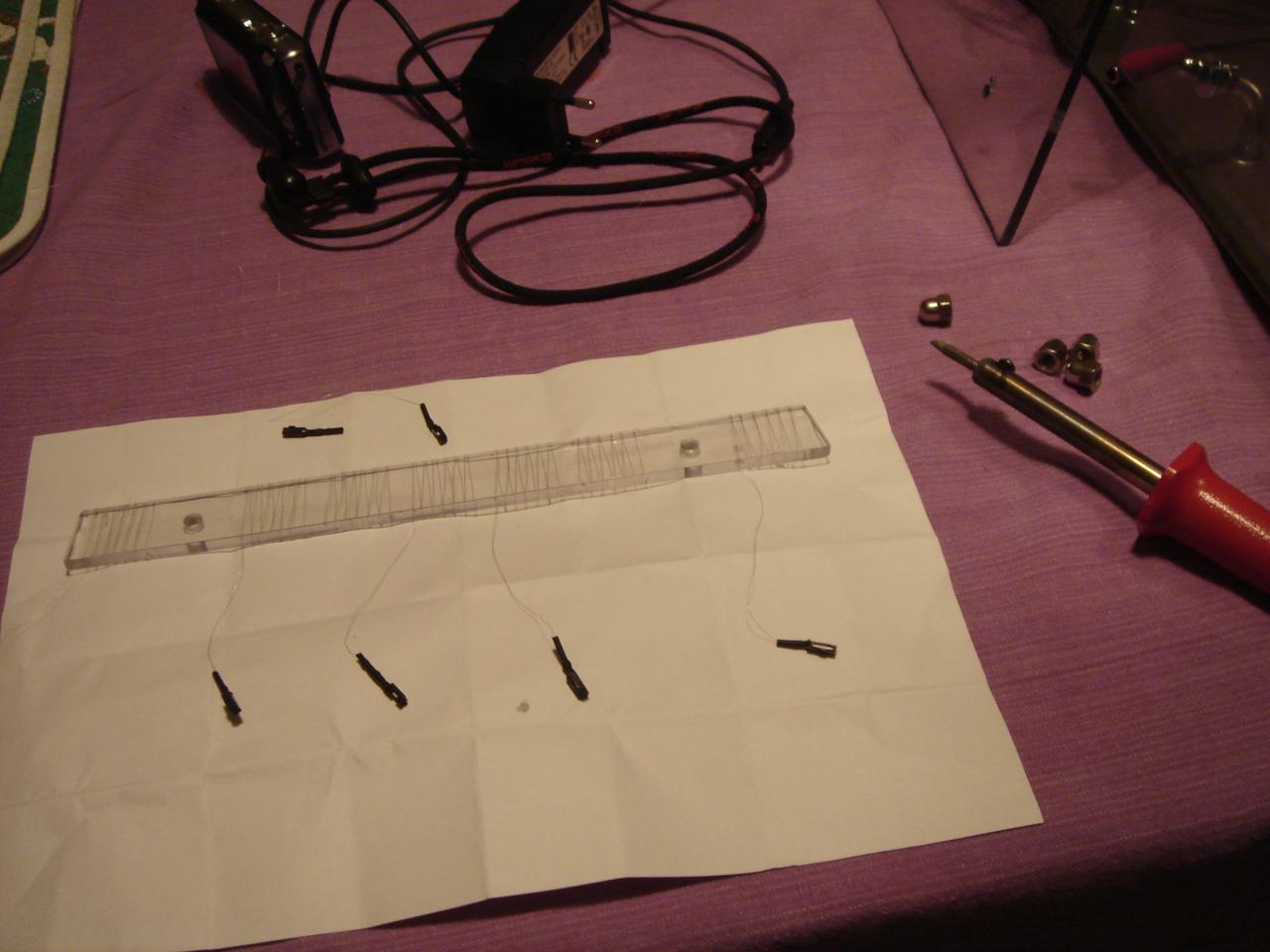
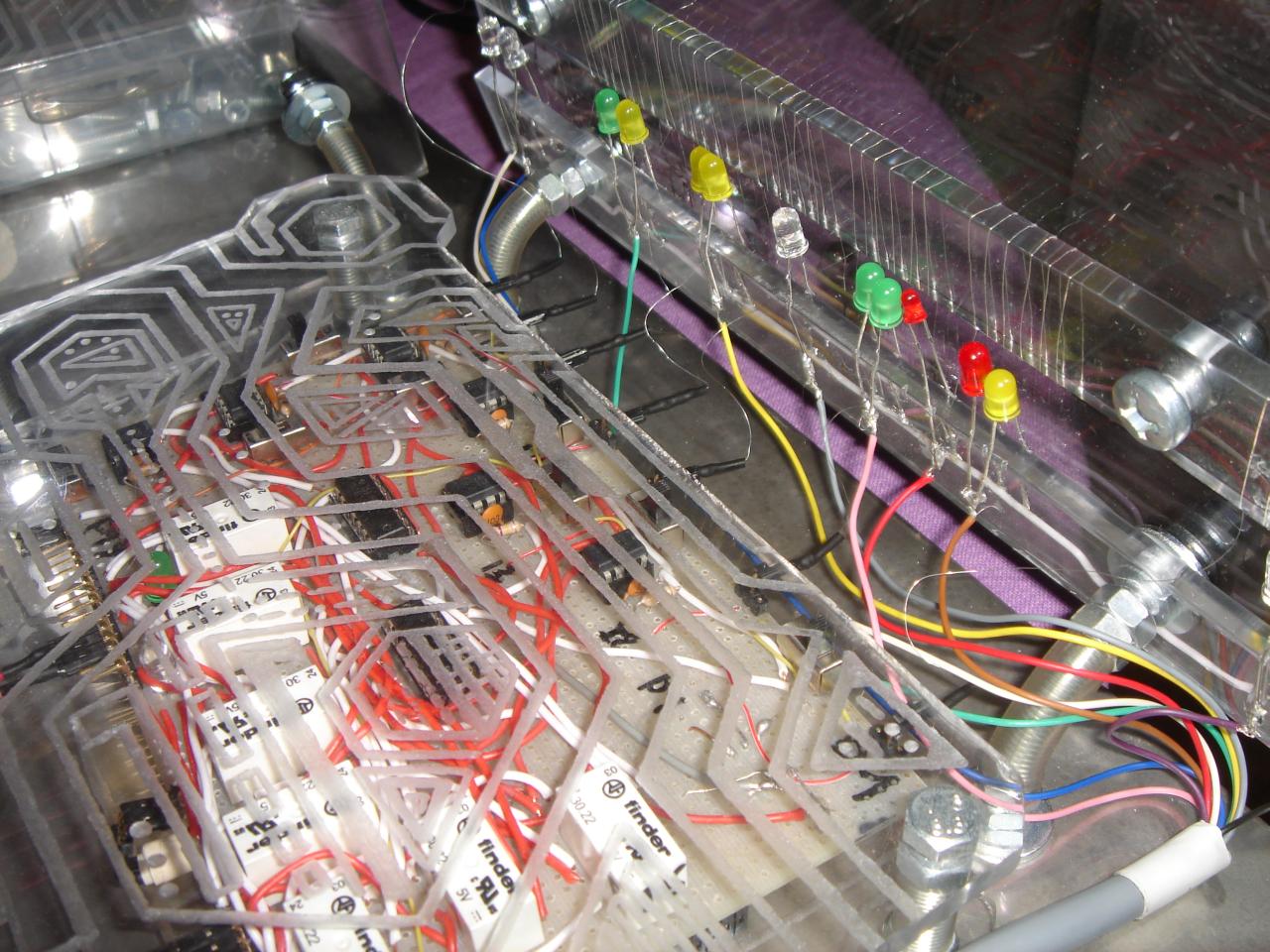
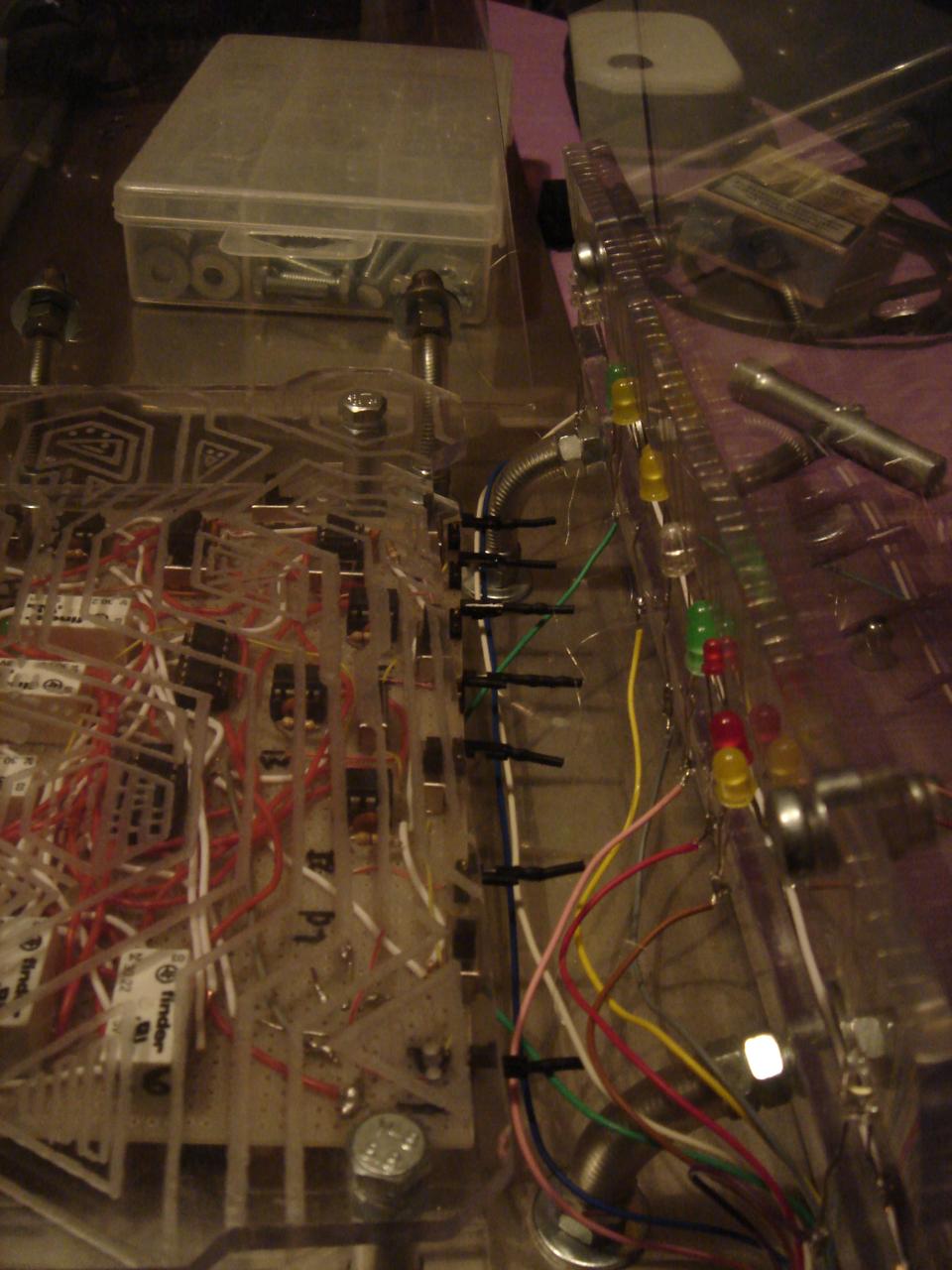
for the top panel I used this 6 LED structure:

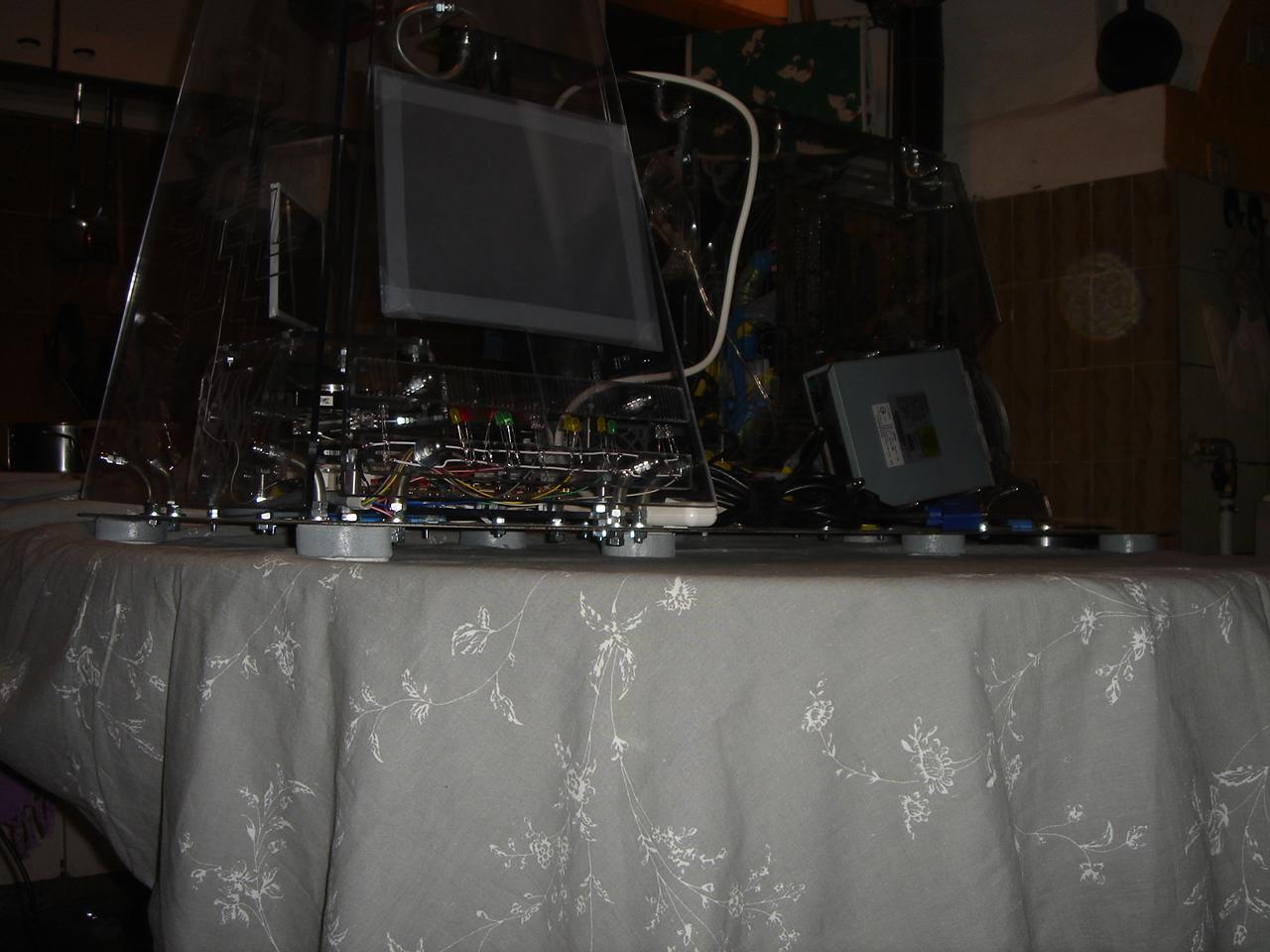
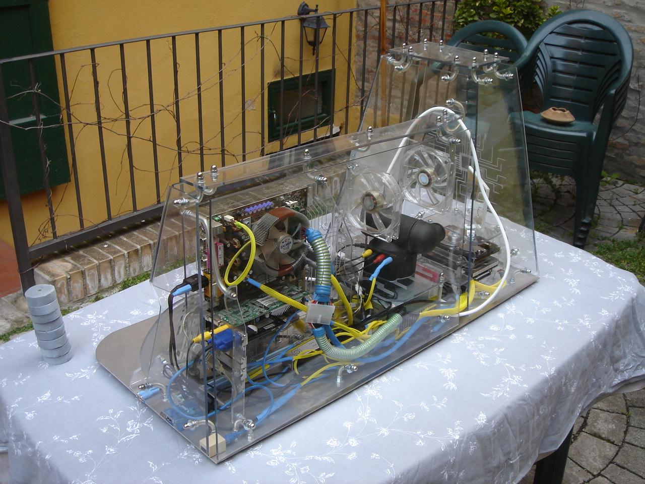
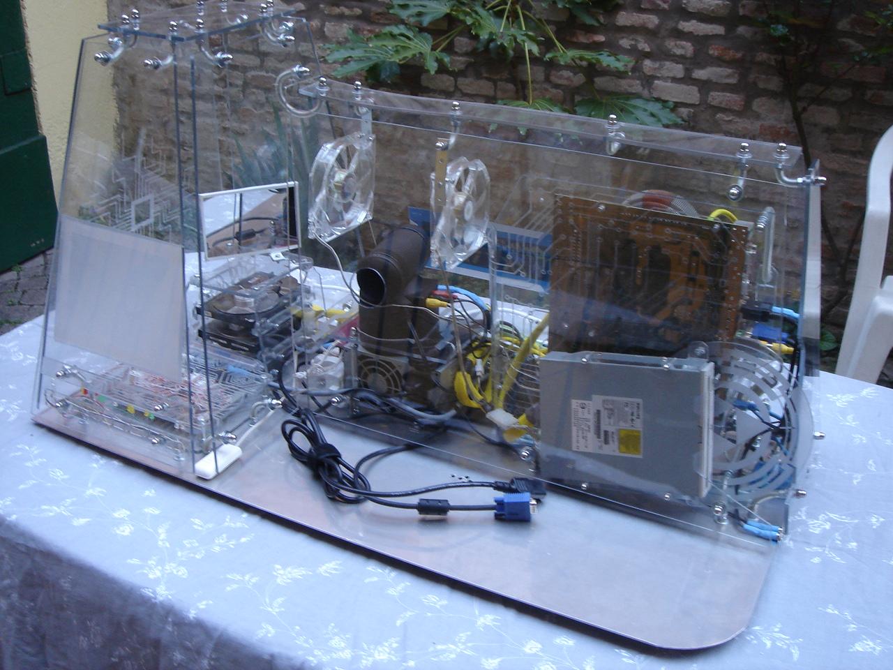
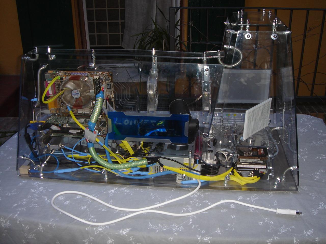
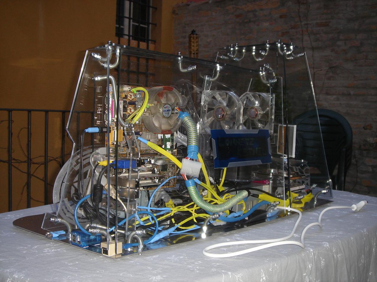
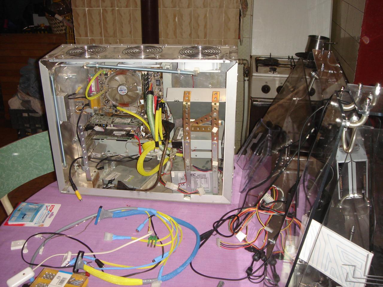
And then I can finish to assemble the PC and I turn it on for the first time!

starting to assemble the PC hardware in the case

And now it’s the moment of the final step: mounting the PC hardware in the case! 😀

[Note from the future: it was not the final step at all! 😀 Don’t worry if you see old hardware in these pics, this is the first version from 2008. Soon I will post the current hardware… (i5 6600k, RX 580, etc.)]

Here I’m disassembling the hardware from my previous mod “AluBT” (it was a similar concept: an all-in-one block with the case behind the monitor, all made in aluminium):

And now I can assemble them in the Kernel:

making the cable that links the sensors circuit to all the case devices

Now that all the components are in place, it’s still missing the cable that links the touch sensors circuit to all the various components in the case.

This is the starting material:

The relay for the audio mute button:

Power and reset connectors for the motherboard:

The switch to turn on and off the videoprojector:

This connector must be connected between the videoprojector and his PSU, in this way:

BEFORE: AFTER:

The molex that must be connected to the PC’s PSU:

The molex for powering all the cold cathode lights:

The fan connectors:

The sensors circuit power supply (the circuit must have an indipendent power supply, because it must be always active to power on the pc, even when the PC’s PSU is powered off):

Covering the wires with some heat-shrink sheat:

And this is the completed cable:

The indipendent power supply for the circuit (it belongs to an old mobile phone):

mounting the video projector in the case

…lol I was joking 😀 NOW arrives the mysterious device!

Do you remember that shape drawn on the PSU cover?
I made a big hole on the PSU cover with that shape, because this is the shape of the device’s base:

And this is the device’s base:

The device has a little speaker, so I made an hole on the case for it:

And for the first time in a pic, this is the mysterious device!

Now I do a simple engraving on the PSU cover:

The mysterious device is turned on… 😀

…and after the mirror, there is another technological device… a plastic bag!

Now it should be clear what is the mysterious device: it is a VIDEO PROJECTOR!
It should be a secondary monitor for the pc, projected on the front wall of the left tower.

This is a test of the projector (the projection is reflected from the mirror on the front screen):

And now I can show two old ugly pics from 2005, when I made a first positioning test of the projector and the mirror 😀 :

mounting a mirror in the case

Now it’s time to unveil the mysterious device! 😀

For this purpose, I must mount over the hard disk structure a very technological device: a mirror!

I glued some layers of poliver and a steel bar behind the mirror:

Then I covered the behind and the sharp edges with a printed drawing and some white tape:

The mirror position should be adjusted with precision, so I mounted it on this steel bar, to be able to rotating and moving it freely.

Well, now that you know that the mysterious device is a mirror, we can move on to something else…

mounting touch sensors, circuit and feedback LEDs

Here I mount the touch sensors circuit, the sensors bar and the feedback LEDs bar (during this operation I broke 3 sensors, that I had to remake…).

I put in place the feedback LEDs bar:

Then I mount the very fragile sensors bar:

…too much fragile… this is the first casualty (that will be followed by other two…):

I connect the proximity sensor to the circuit and I close the side panel:

Turning on and testing the sensors:

Here I must remake the 3 broken sensors (2 hours of tension… I was feeling like defusing a bomb 😀 )

And finally the assembled circuit with all the sensors working:

A couple of pics of the sensors in the dark: