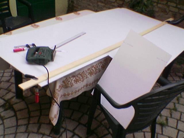
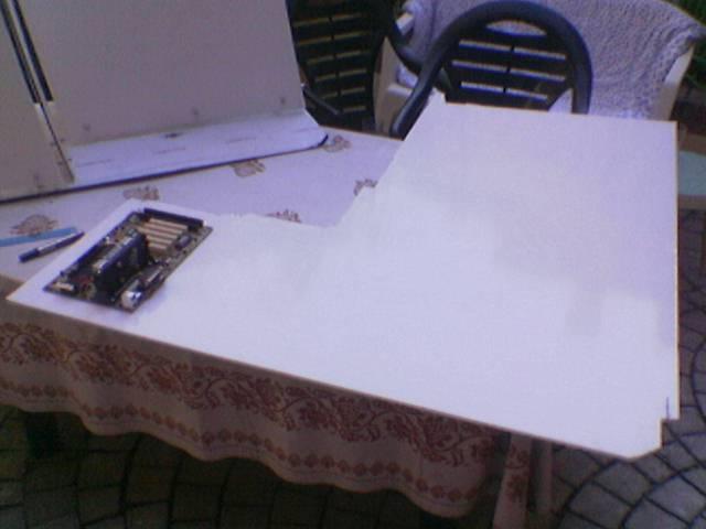
All started from here…
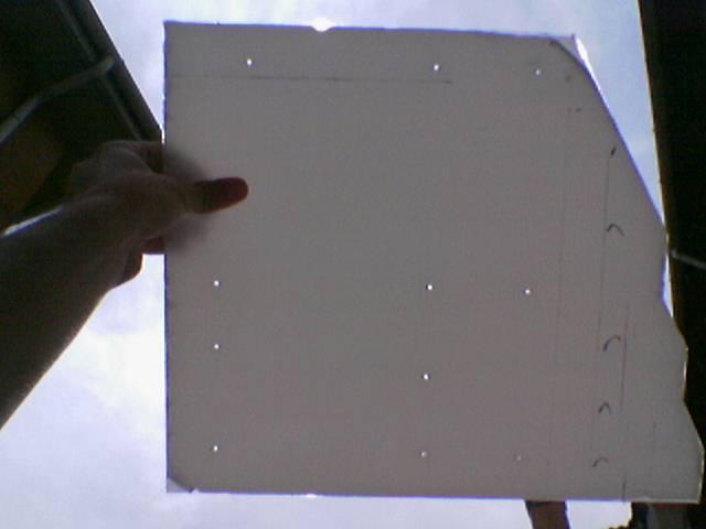
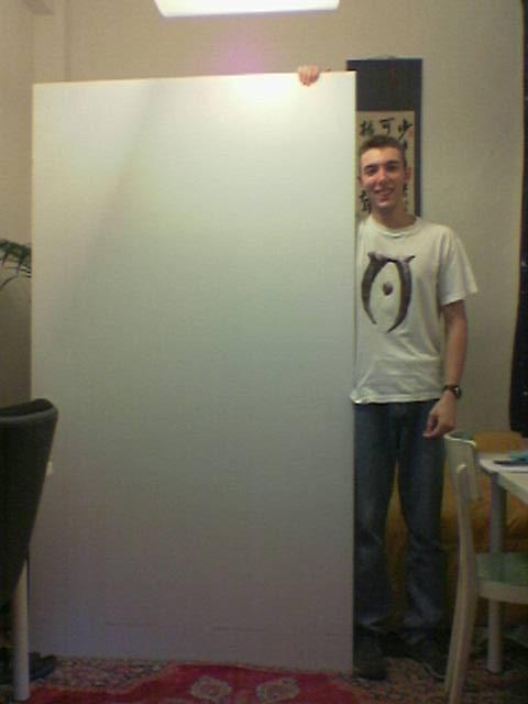
I went to buy the polycarbonate: I took a panel of 2.05 * 1.15 m ![]() :
:
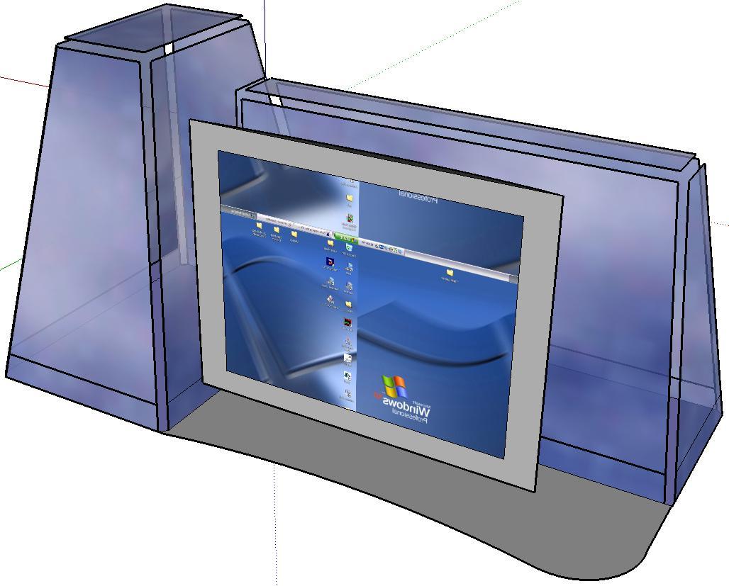
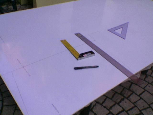
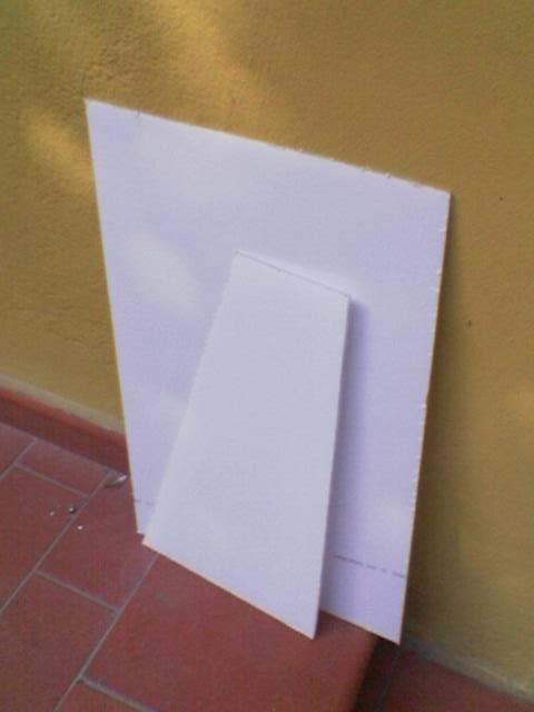
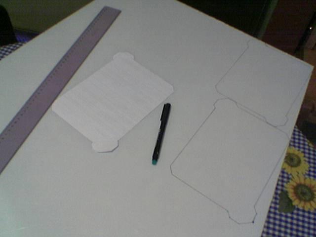
This is a draft of the outer chassis:
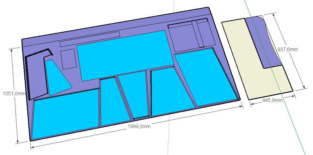
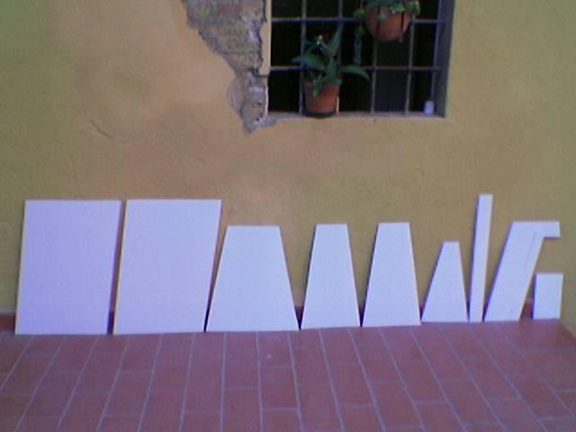
And these are the pieces that I should cut from the panel:
All started from here…
I went to buy the polycarbonate: I took a panel of 2.05 * 1.15 m ![]() :
:
This is a draft of the outer chassis:
And these are the pieces that I should cut from the panel:
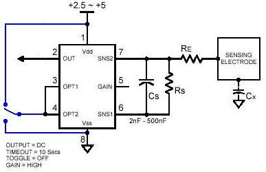
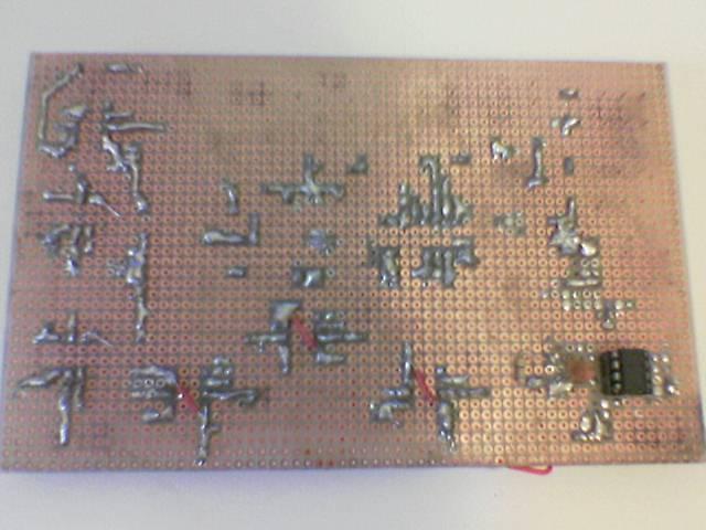
This is the making of touch sensors’ circuit:
(For the making of this circuit I must do special thanks to Axeman for his help)
I ordered 8 qt110 (the chips that control touch sensors):
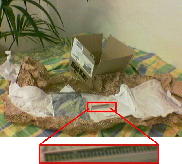
(there are only 7 switches because I toasted one while I was soldering it 🙁 )
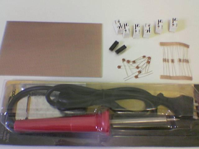
First purchases (resistors, capacitors, two integrated 74ls06 (which reverses the signals from QT110, for the relays), 6 relays and a new soldering iron)
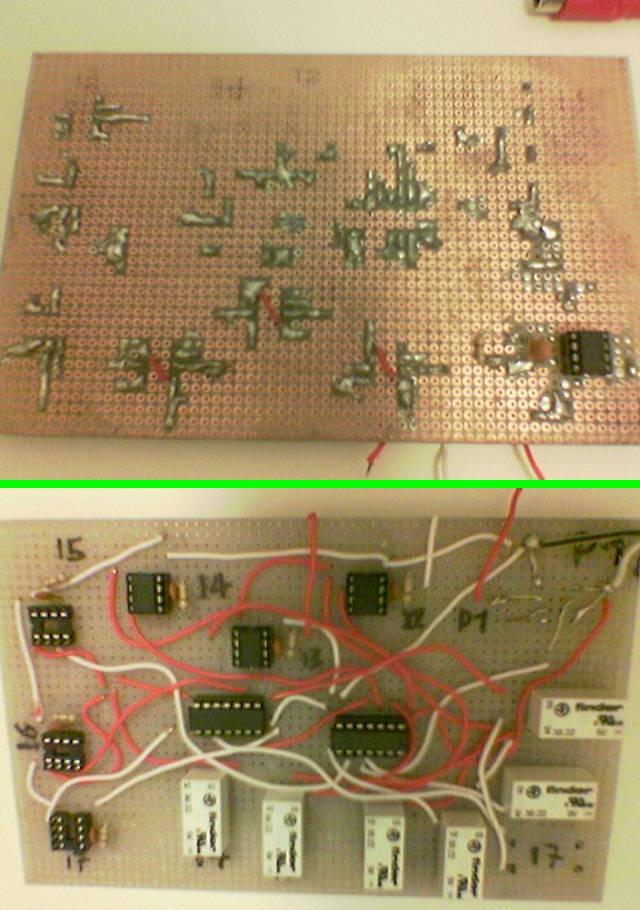
Begin soldering:
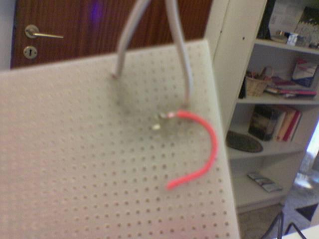
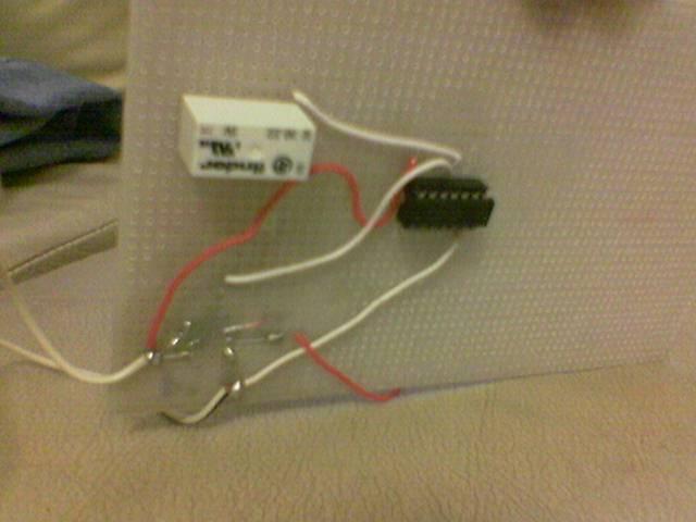
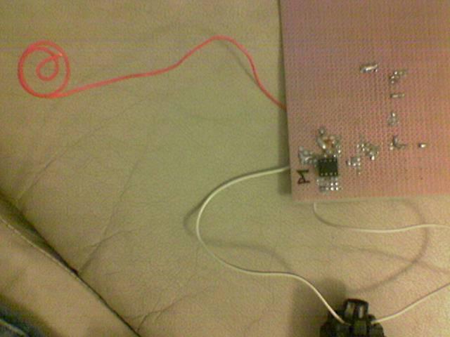
This is the first touch sensor (the sensor is the red cable rolled)
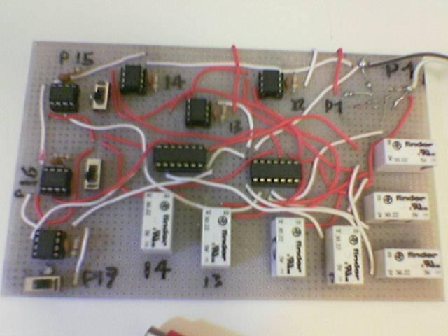
Then I mounted the other chips:
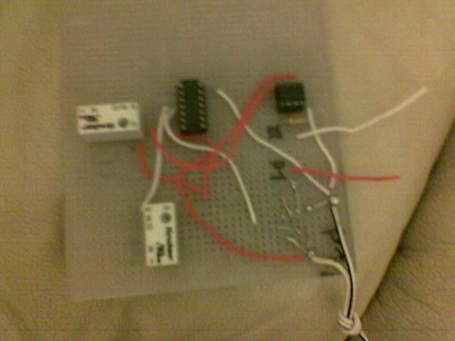
Other purchases: some LEDs, another relay and some mini-switches …
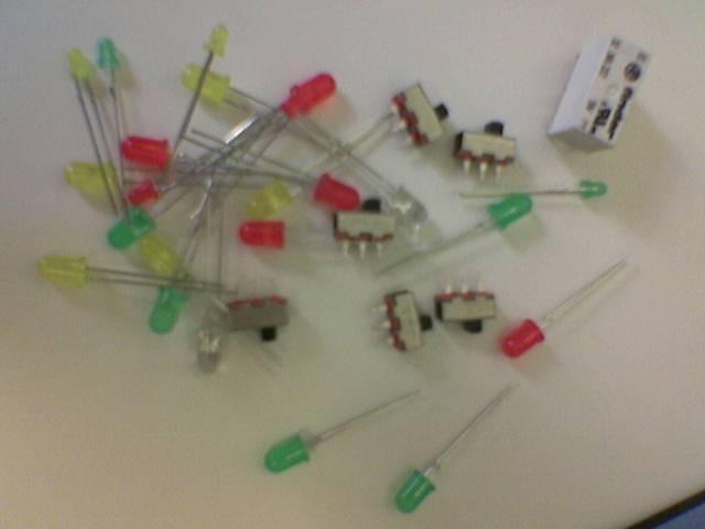
I used mini-switches to make a little change to the original circuit (the blue line that I added on this circuit). With these switches, now I can select the chips’ behaviour: button or switch 😀
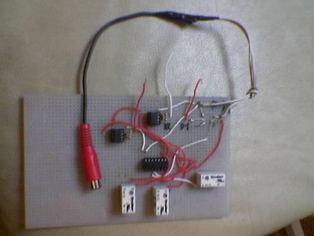
So, here i have completed the first step of the touch sensors’ circuit:
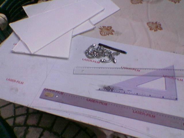
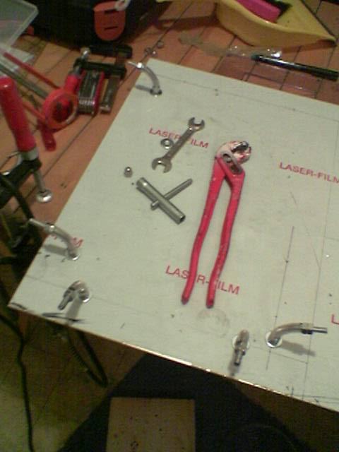
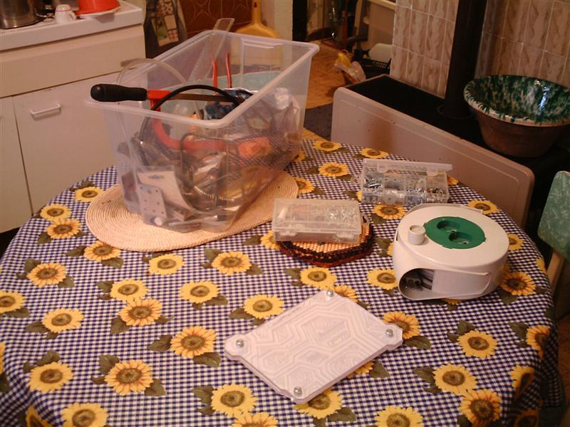
Other purchases:
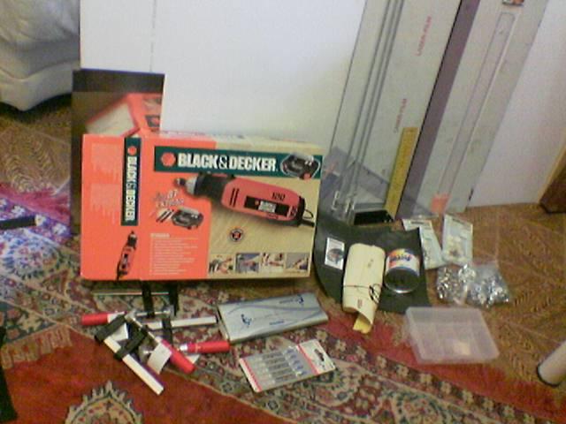
Starting from left:
– Small panel of very thin stainless steel
– Black & decker rt650
– Some clamps
– Carbon paper
– blades with large teeth for the electric saw
– Dremel accessories
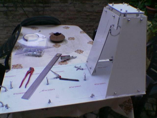
– 3 steel bars
– Drawing tools
– Stainless steel base of the case (2.5 mm thick)
– Sanding paper and polish
– White rubber feet
– Box for screws
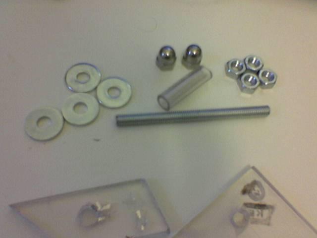
– 160 bolts
– 160 washers
– 80 closed-head bolts
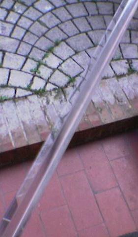
– wooden bar 2.4 m long (2.4 m is about the diagonal of polycarbonate panel)
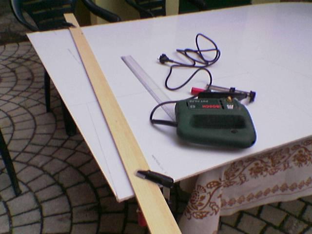
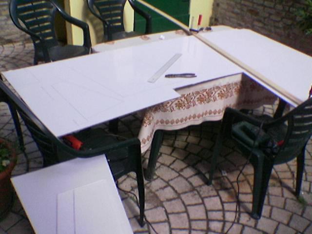
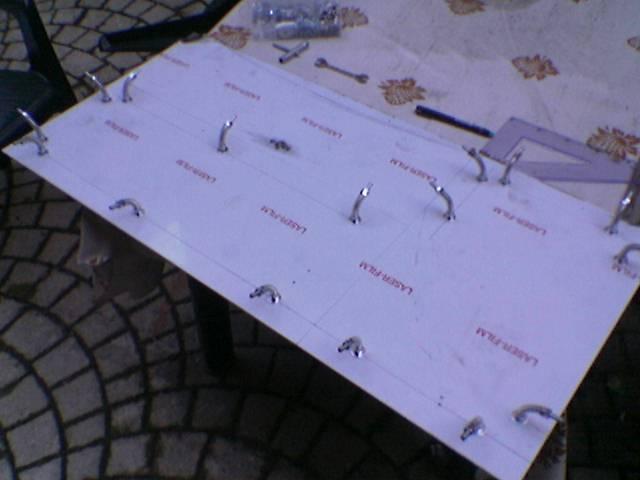
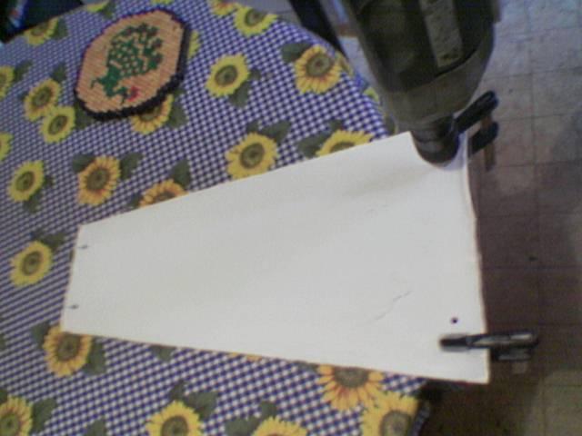
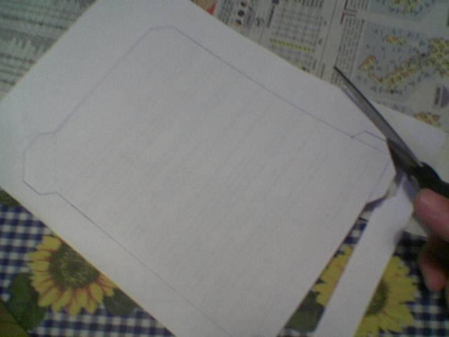
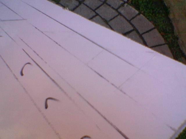
I drew the shape of some pieces in the film:
…And I began to cut the first cm with the dremel.
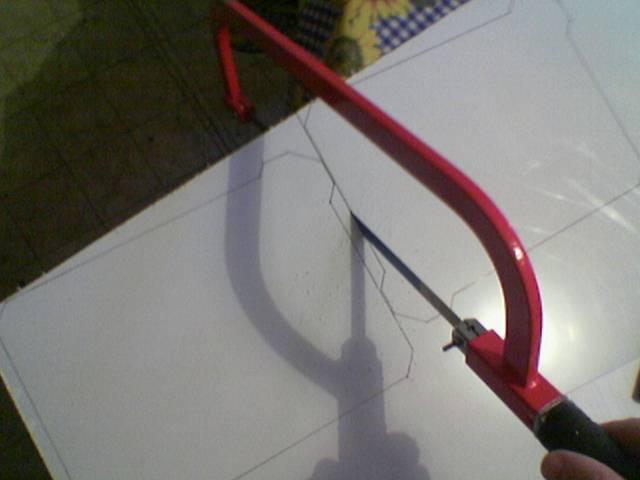
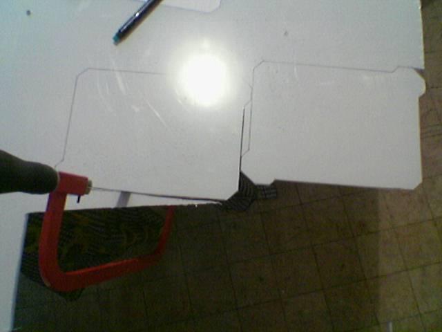
Then I started cutting with an electric saw:
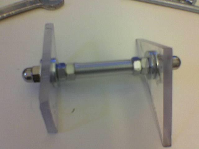
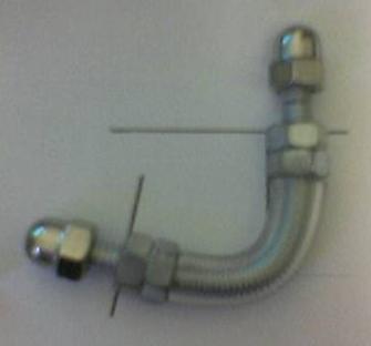
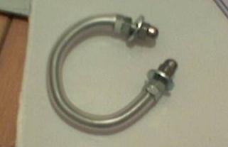
These are the structural joints of the case. They are made from pieces of steel bar and they keep walls of the chassis fixed together.
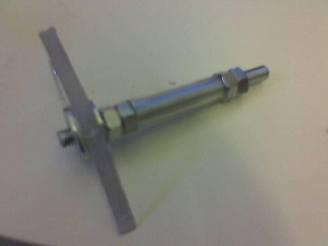
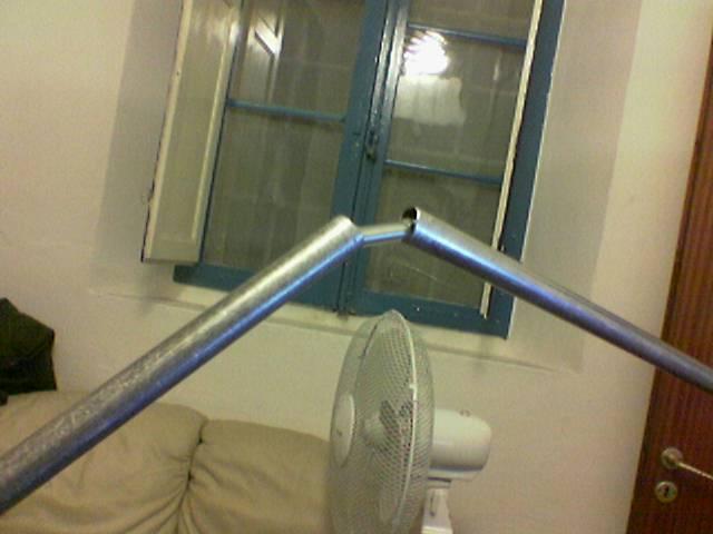
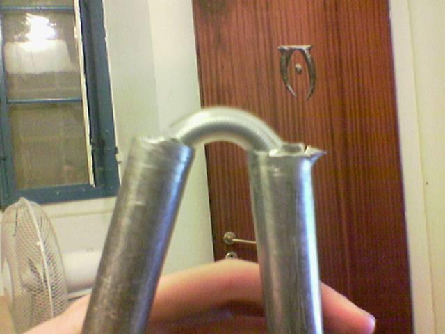
I folded the bar’s pieces using two long iron pipes:
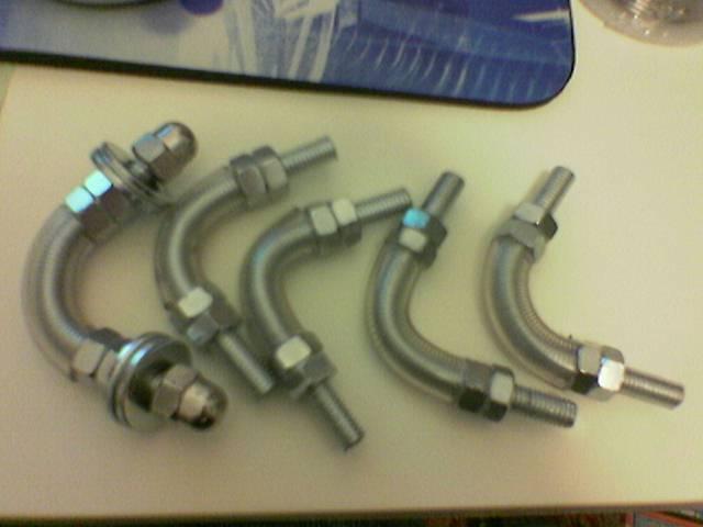
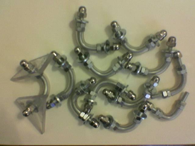
More joints:
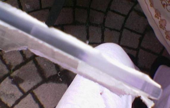
Polishing edges of the panels:
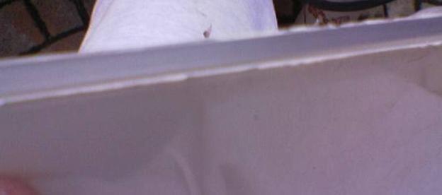
Raw edge:
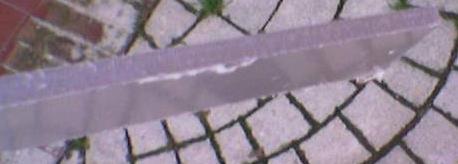
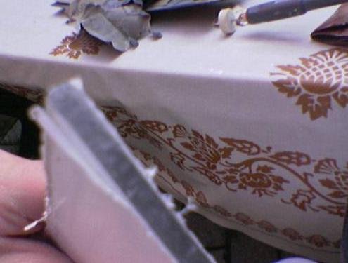
The first step with the dremel:
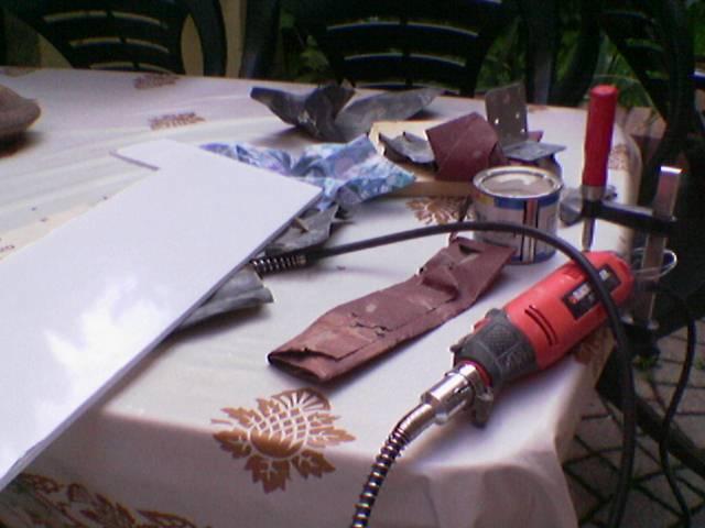
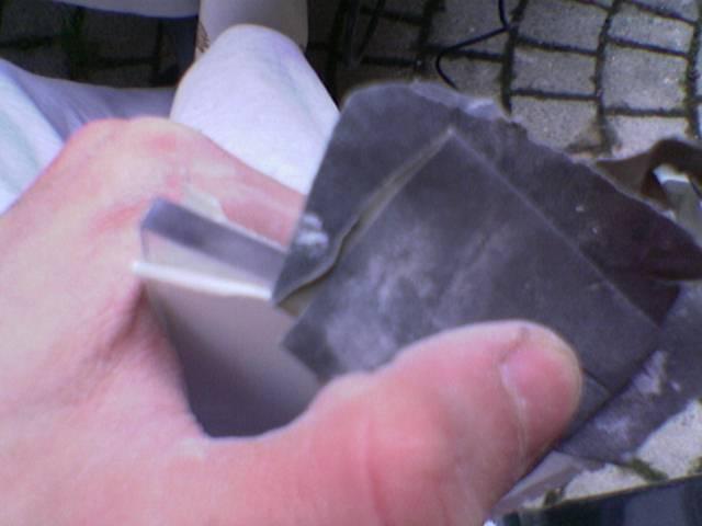
The other tools:
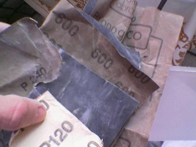
Sanding with this sequence of sanding papers: 120, 240, 600, 1000
Some flaws in the sanding:
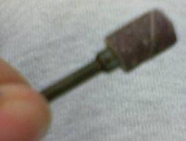
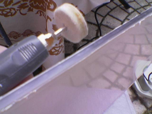
To smooth these flaws I use this “wool” cylinder:
Now the edge is flawed and ruined again, so I repeat the use of sanding papers, from 240 to 1000
Now the edge is sufficiently smooth to finish with the polishing paste.
The edge polished
And finally the last polishing with toothpaste to achieve the final transparency:
UPDATE: These are a lot of steps, but they must be done only for a very damaged edge (like these edges cutted with a manual electric saw). For an edge cutted with more precise tools (for example an industrial circular saw) these steps are enough:
– sanding paper 240
– sanding paper 600
– polishing paste
– toothpaste
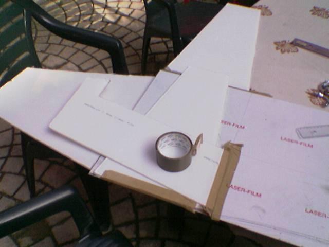
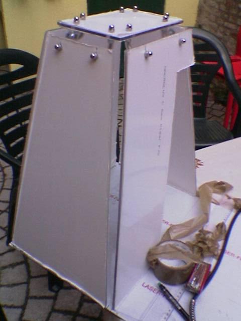
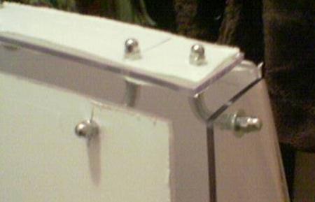
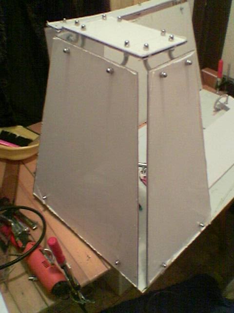
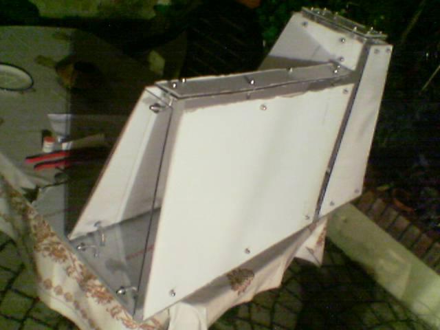
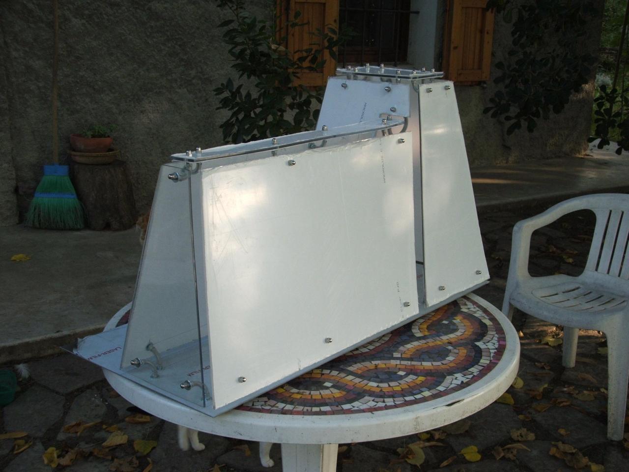
Now I began to mount the outer chassis, using the joints that i have made above.
I took some measures…
Mounting the panels with tape:
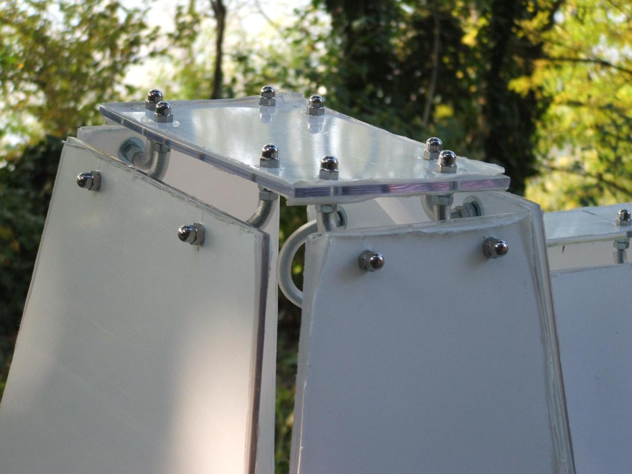
Once that I have taken measures, I needed holes on the top of the tower, for mounting the joints:
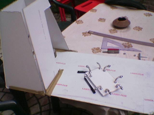
The roof of the tower is mounted:
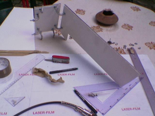
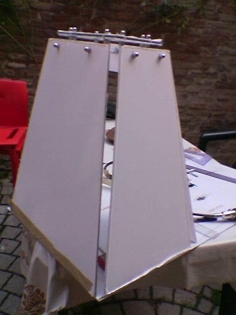
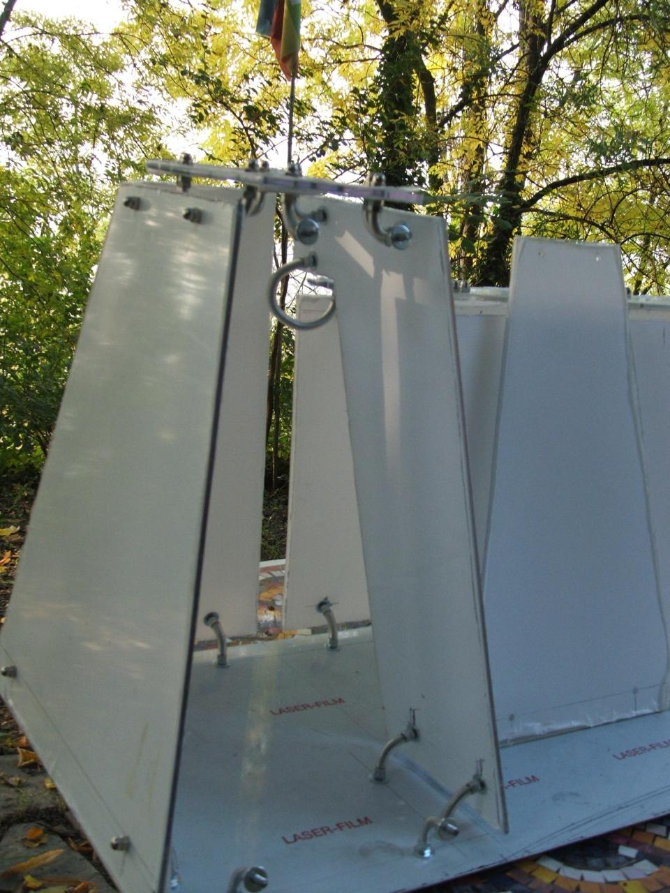
And now, the part of case placed behind monitor.
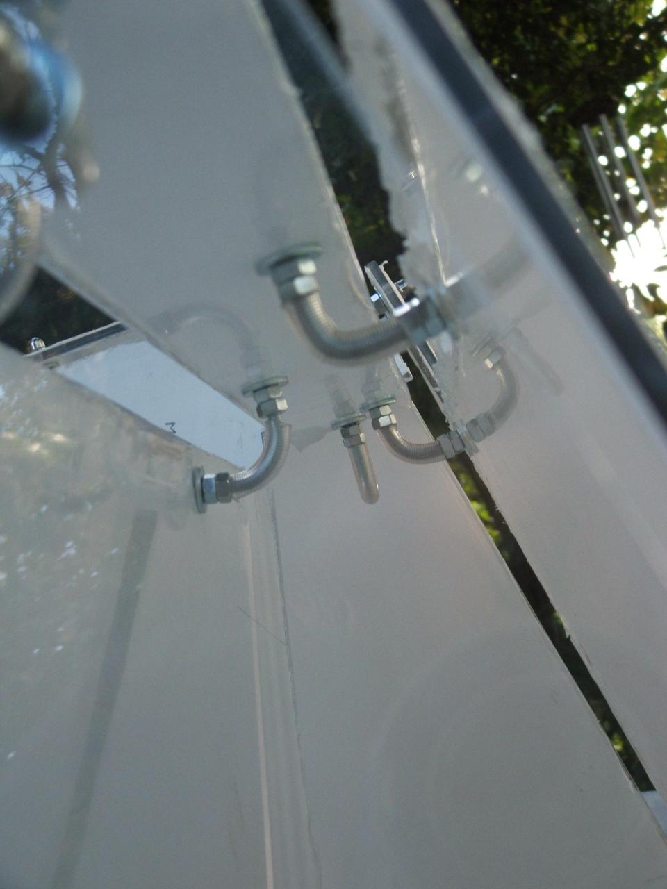
A special joint:
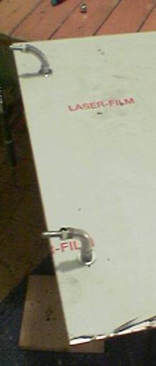
Then I fixed the top at the end of the right panel (the panel without protective film):
And then the panels of the left tower, using the special joint:
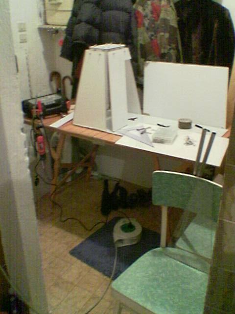
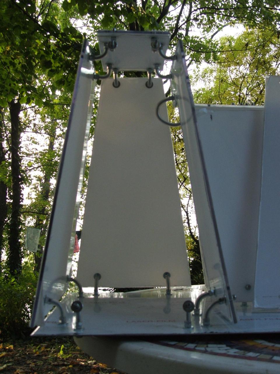
Then I taken other measures, I made some holes, etc…
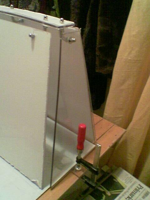
I mounted the two parallelogram shaped panels:
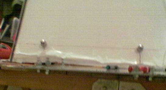
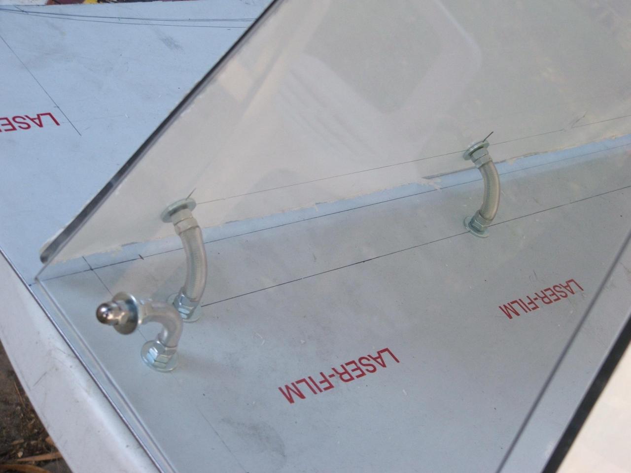
Two details of the transparent panel:
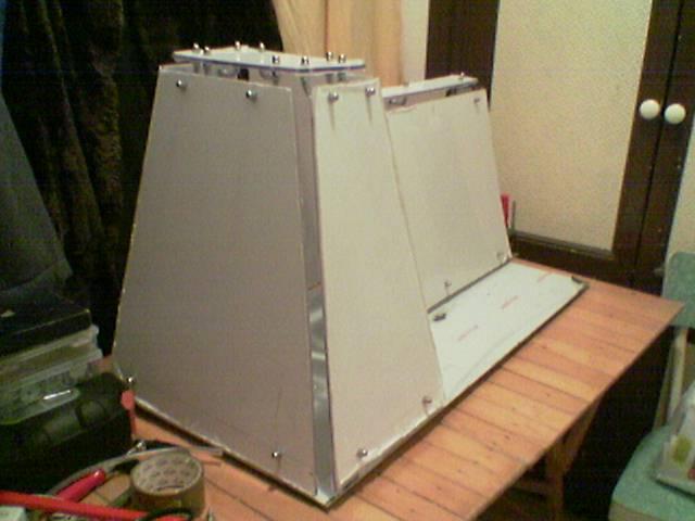
I started to mount the chassis on the stainless steel base, always using the same joints.
I began mounting the tower:
I’ve made other joints (and I fixed them on the base)
I Began to mount these panels:
I had to shorten this joint:
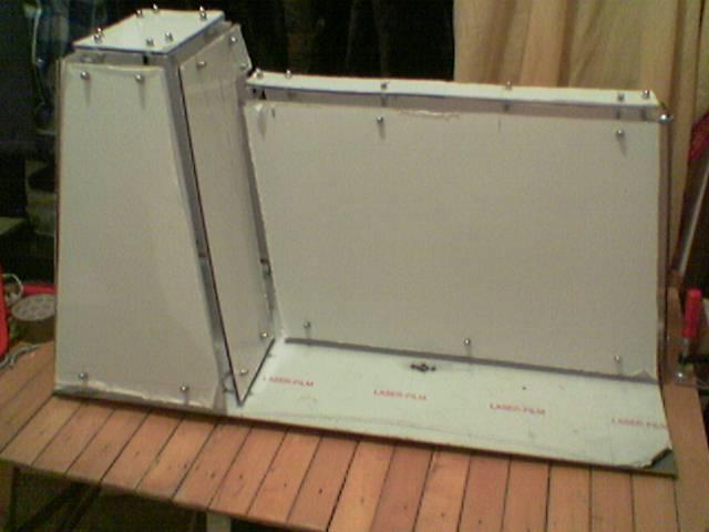
I begin to mount the panels of the section placed behind the screen:
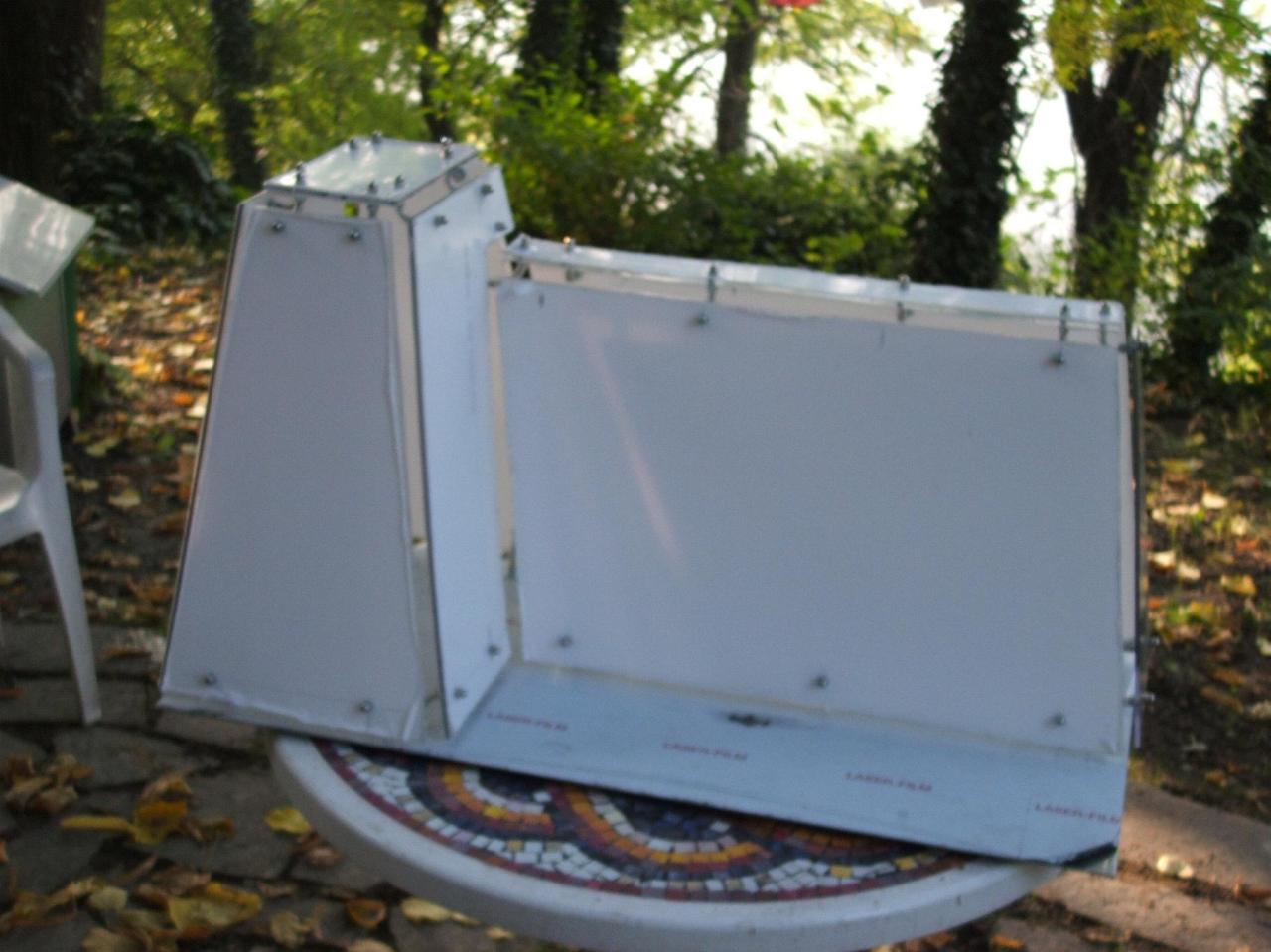
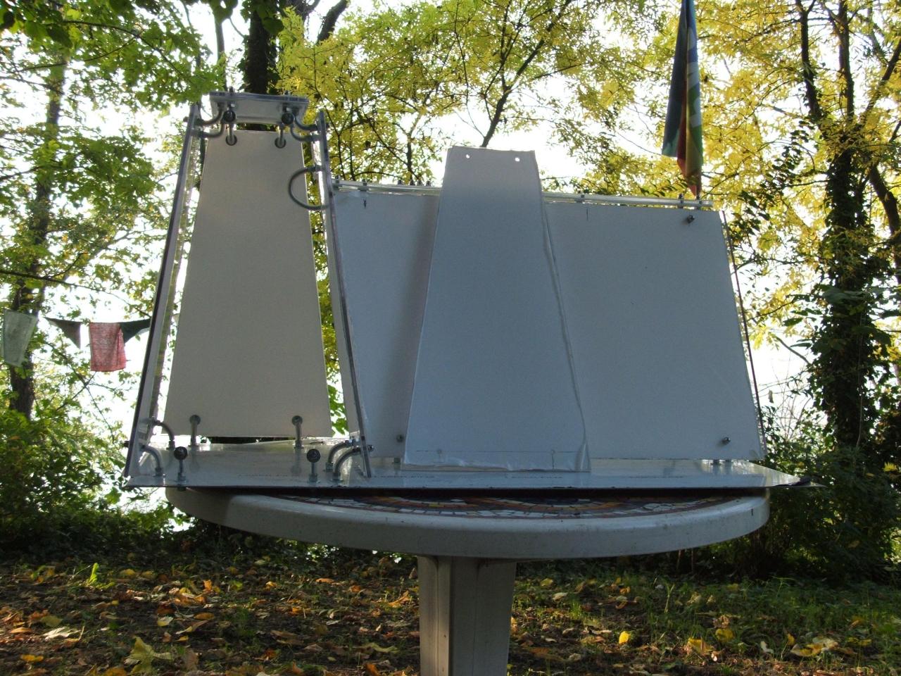
And here I mounted the last panel (the one without white film):
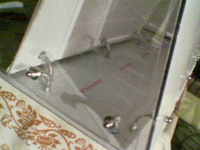
Here you should see that there is a small gap between the base and the panels:
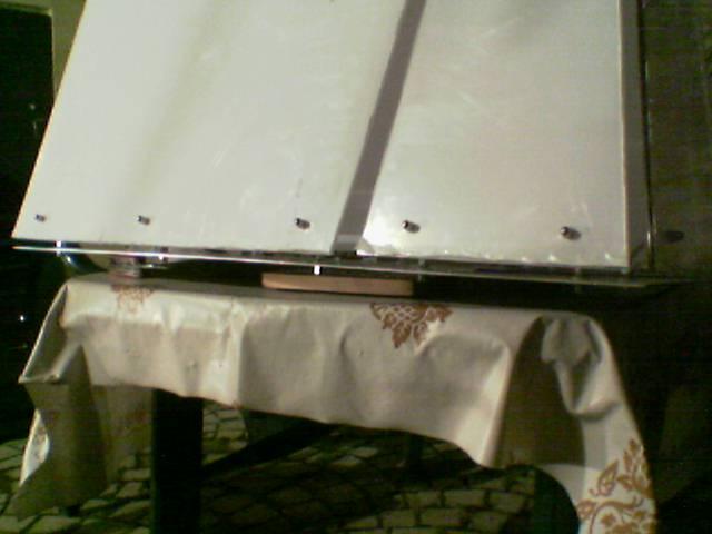
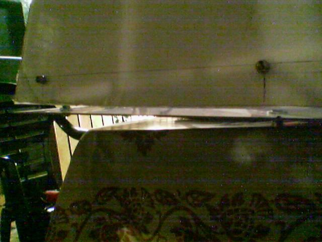
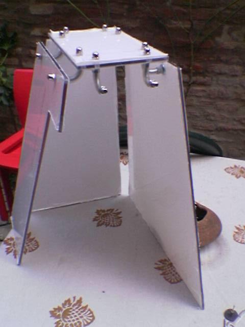
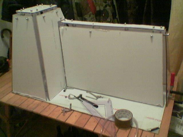
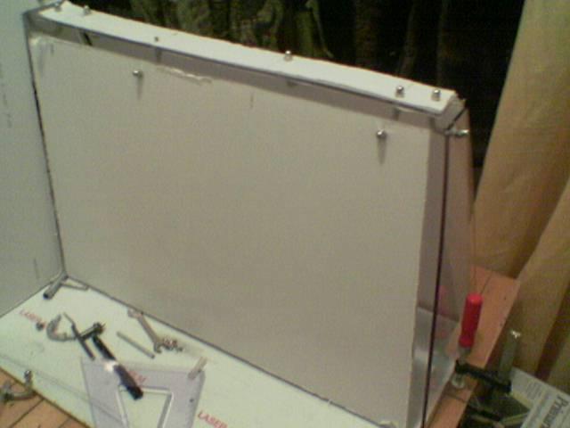
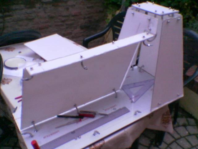
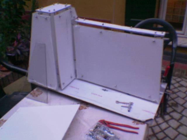
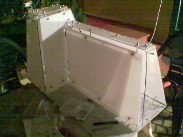
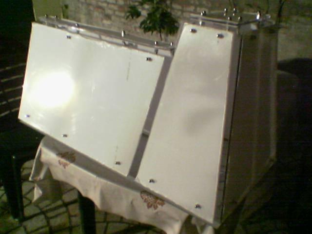
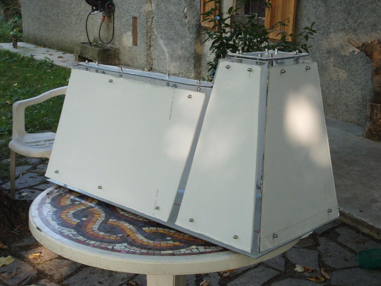
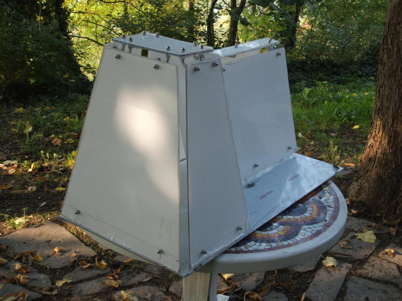
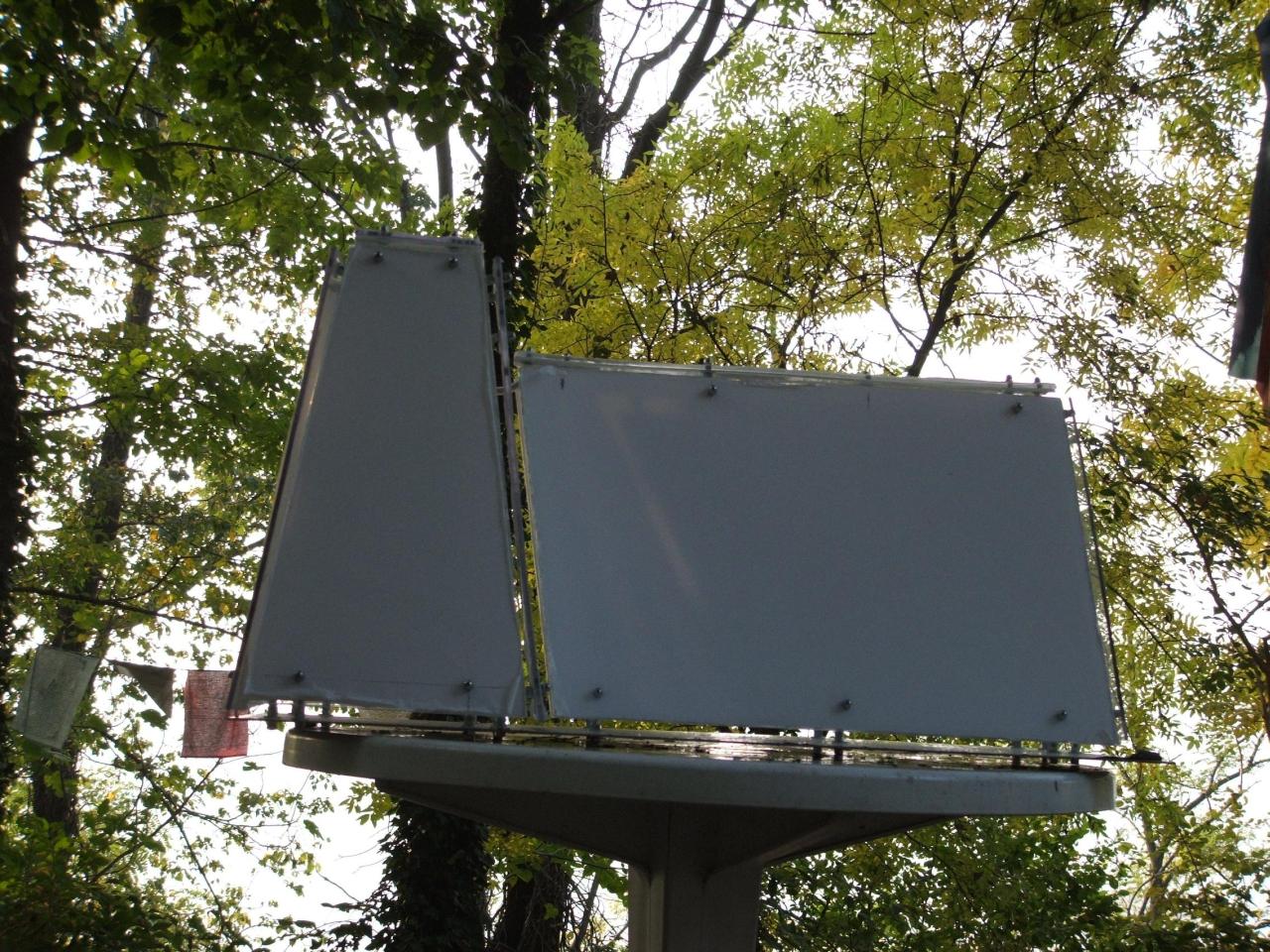
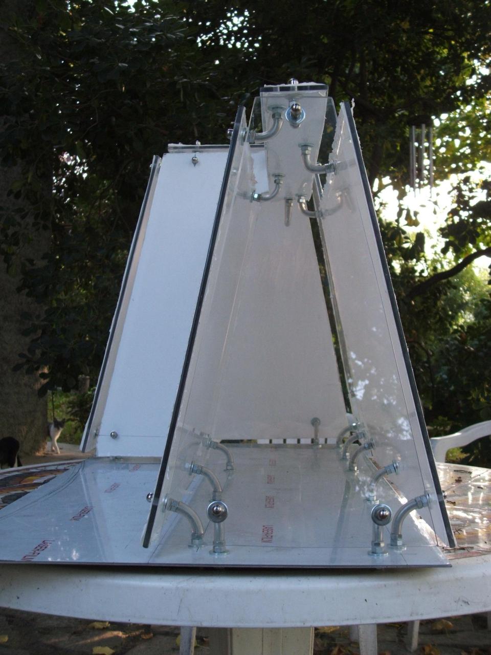
And this is the completed outer chassis:
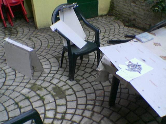
Some better photos of the outer chassis:
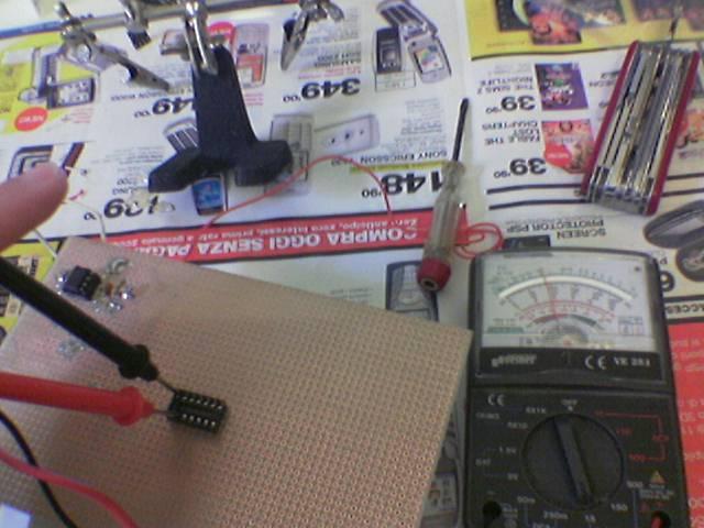
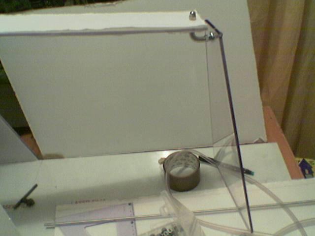
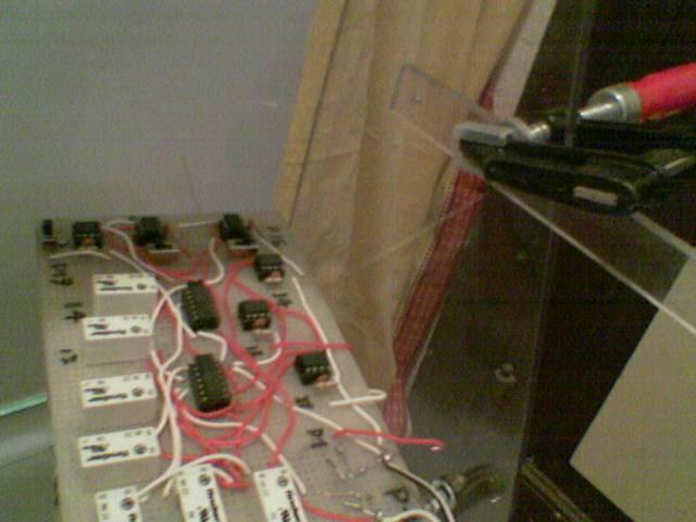
I have done a test with sensors:
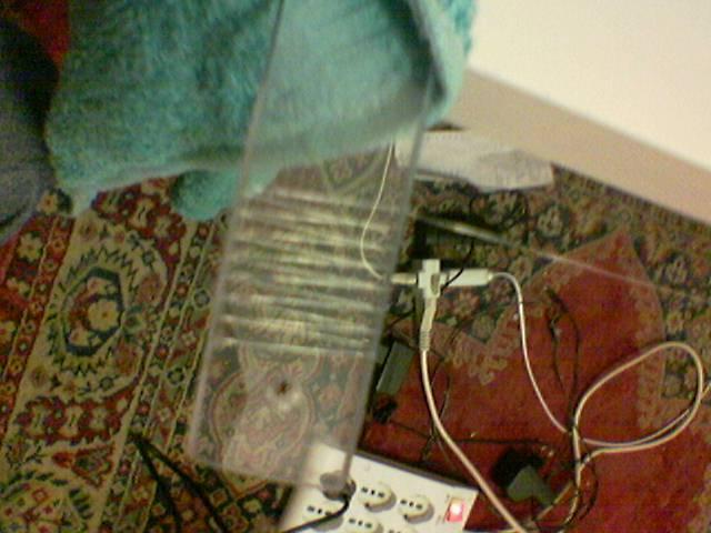
I took a rounded floppy cable broken and I took a single wire, then I removed the plastic sleeve from the wire, and I took a single copper fiber, to use it as sensor:
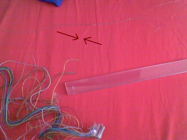
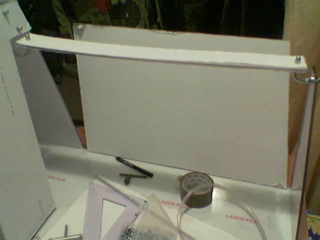
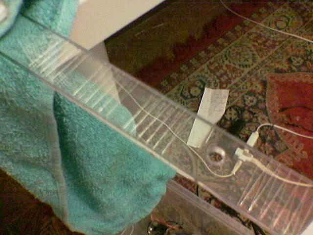
I rolled the single wire around a polycarbonate bar, and I welded it to the circuit, then I temporarily fixed the bar behind a panel:
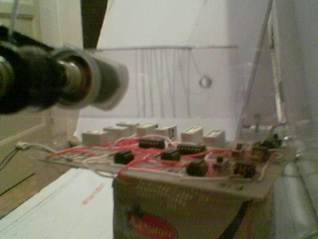
…and everything worked! 😀 (the wire must be very thin to work properly behind 5mm of polycarbonate, and this is the thinnest wire that I have found in my home)
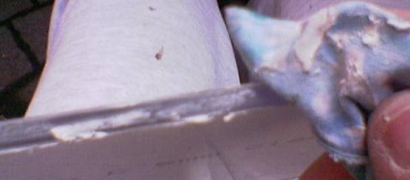
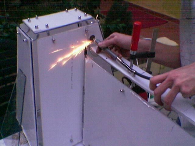
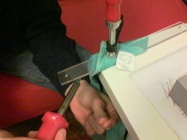
To fix the wire to the bar, I must heat the wire near the edge of the bar with a soldering iron.
Here I’m pushing the hot wire in the edge of the bar: heat melts the surface of polycarbonate and the wire fits in the edge. After this, the wire is fixed within the bar.
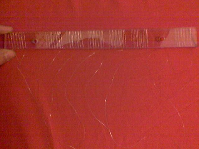
A finished sensor:
For a mistake, I have ruined the bar, so i have to restart from scratch:
So, I cutted the bar, then I polished its edges and I drill the holes:
Then I have adjusted the joints for the sensor bar:
Then I restarted to fix the wires in the bar, with the same method said above:
Done! Now I must build a “chassis for the circuit”.
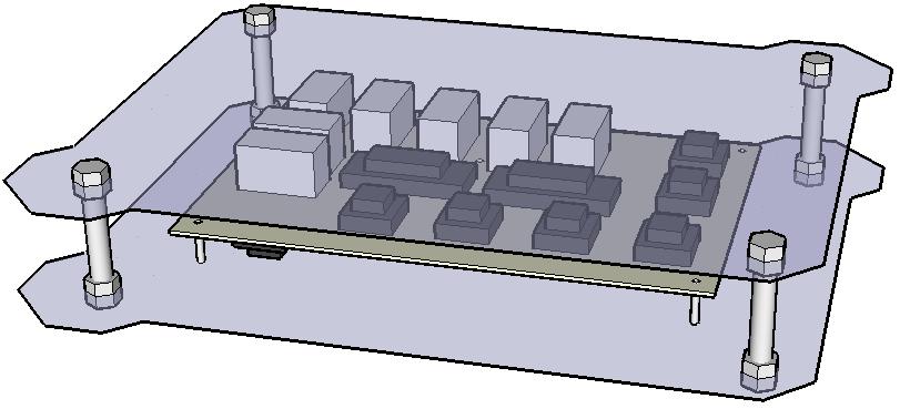
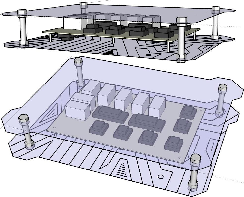
This is a first draft of the circuit chassis:
Then I built it:
I cut the pieces:
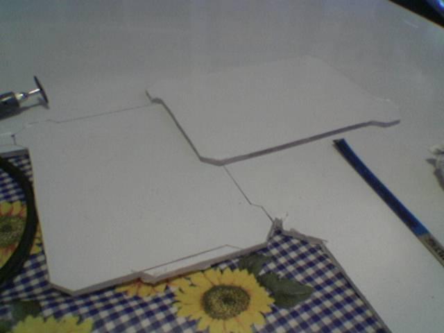
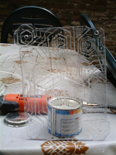
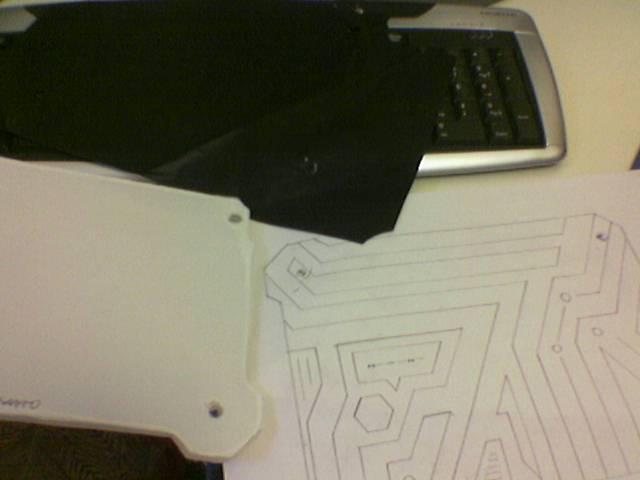
These are the two raw panels:
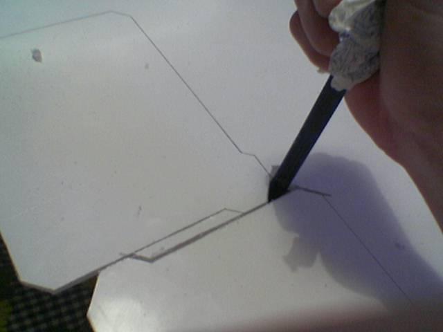
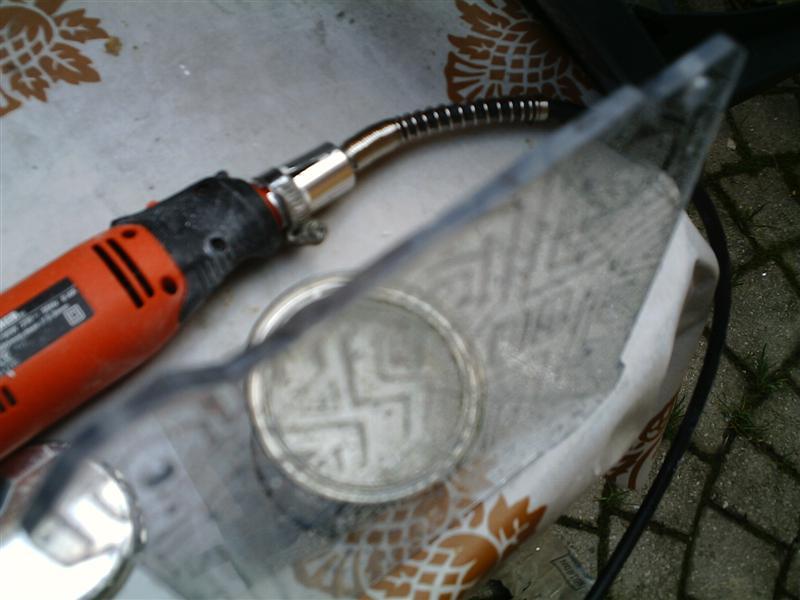
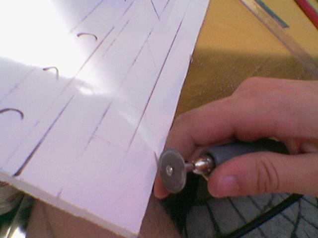
I did a test with a rounded-tip engraving tool of the dremel.
The drawing (the knife is for compare the size):
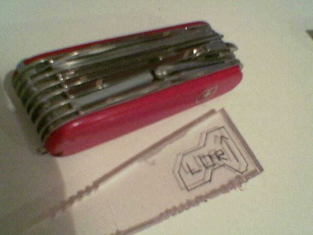
The engraving:
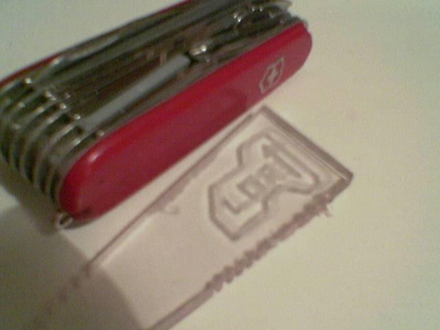
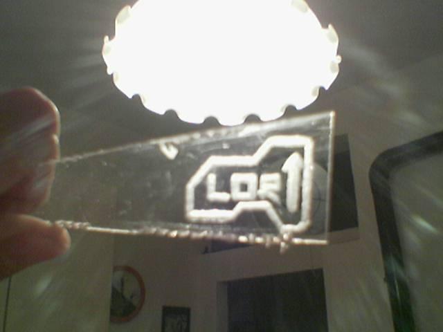
The illuminated engraving:
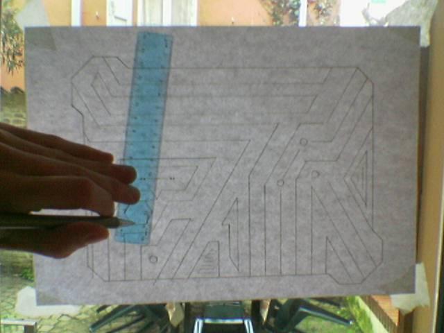
I draw on paper the engraving (under the paper there is a carbon copy sheet):
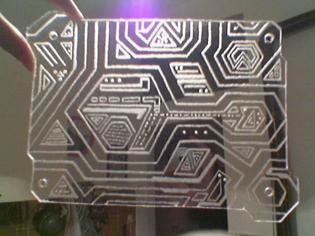
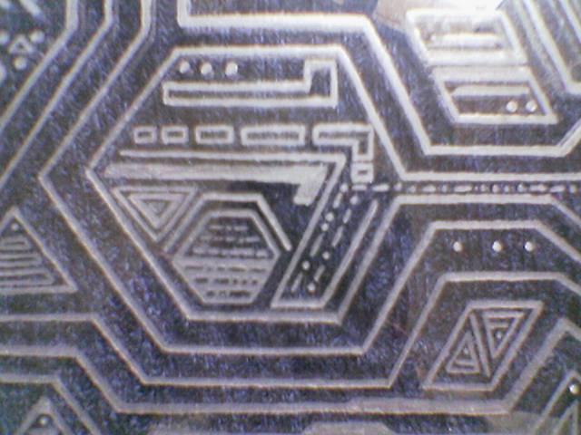
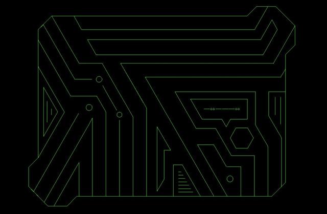
I made the drawing… (trying to follow the style of some environments of Tron 2.0)
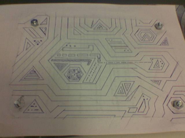
The drawing imprinted on the protective film:
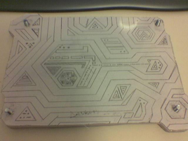
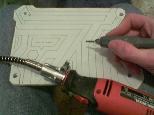
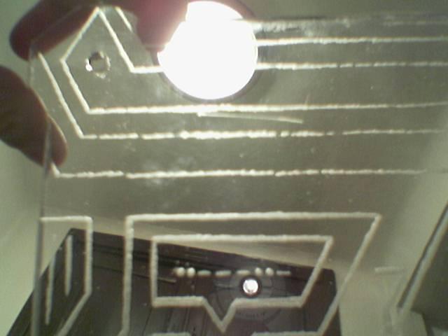
The first pass of the engraving (this method require two steps: a first pass with the protective film, and a second pass without the film to refine the engraving):
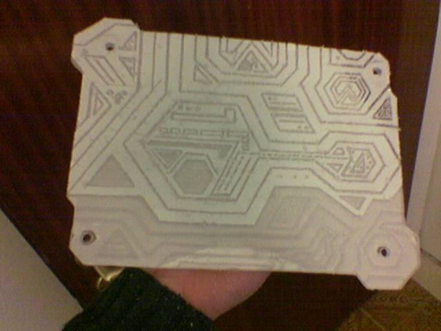
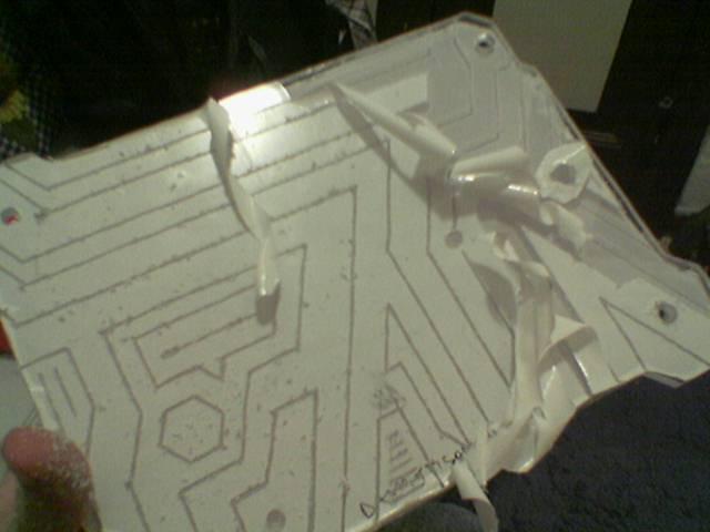
I remove the remaining film:
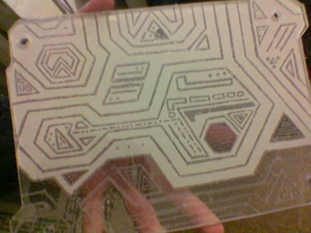
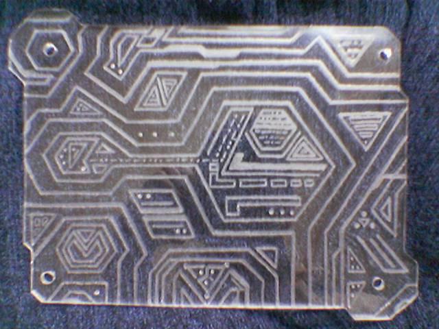
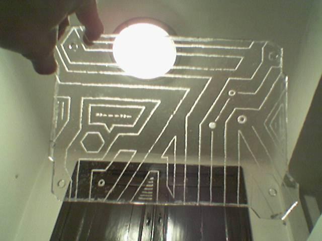
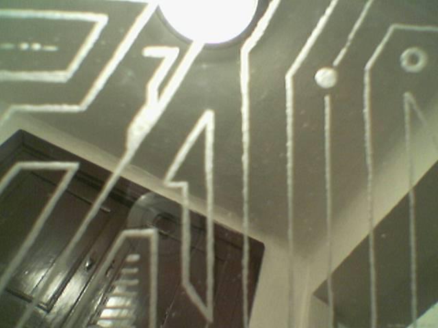
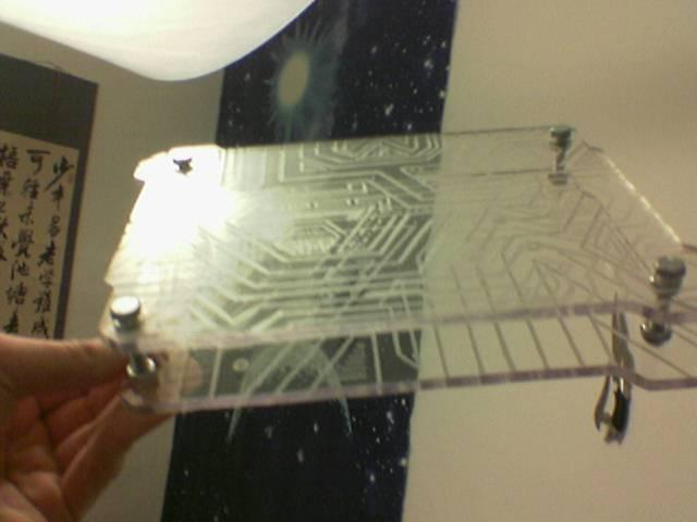
The engraving enlighted (this is only the first pass, so the engraving is a bit raw):
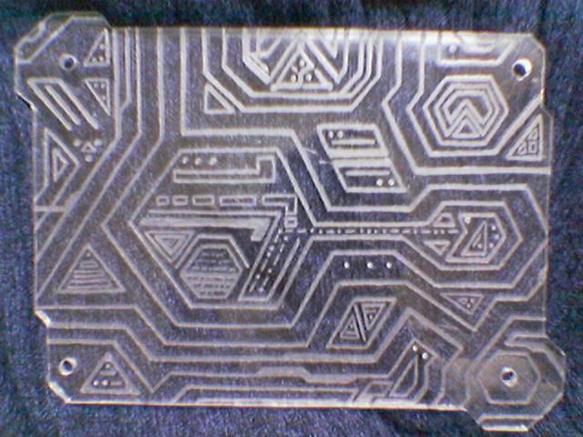
I polished the edges of the engraved panel:
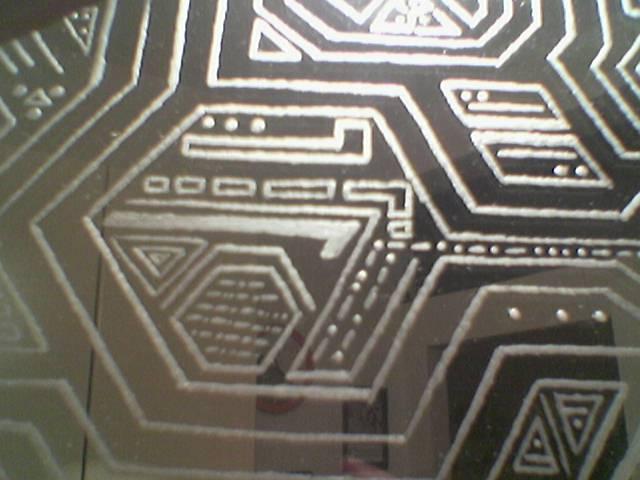
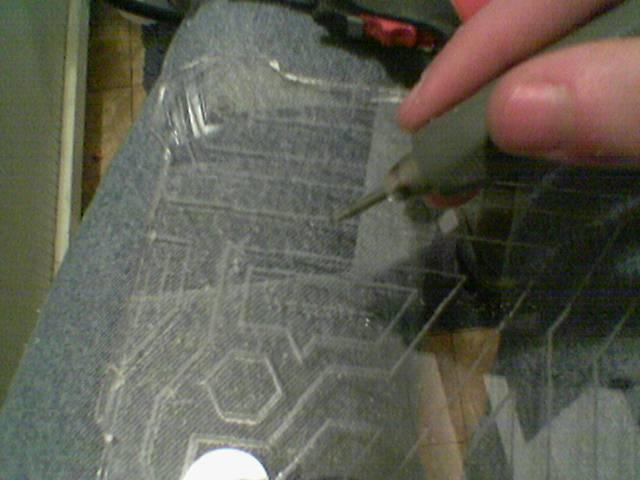
Then I have done the second pass of the engraving, to refine every single groove:
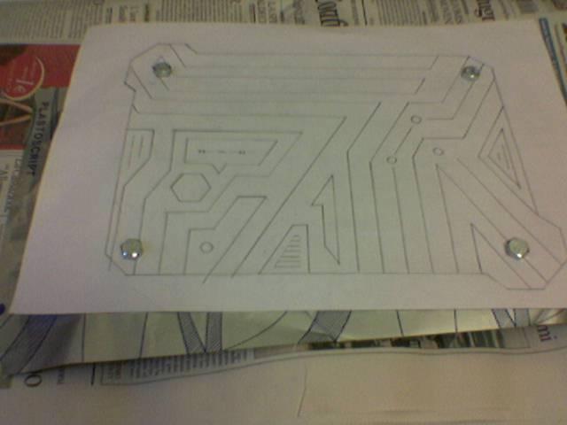
I made the drawing for the lower panel of the circuit chassis:
And a preview of this drawing on the structure:
Engraving the lower panel:
Finished the first pass:
Then i proceed with the second pass:
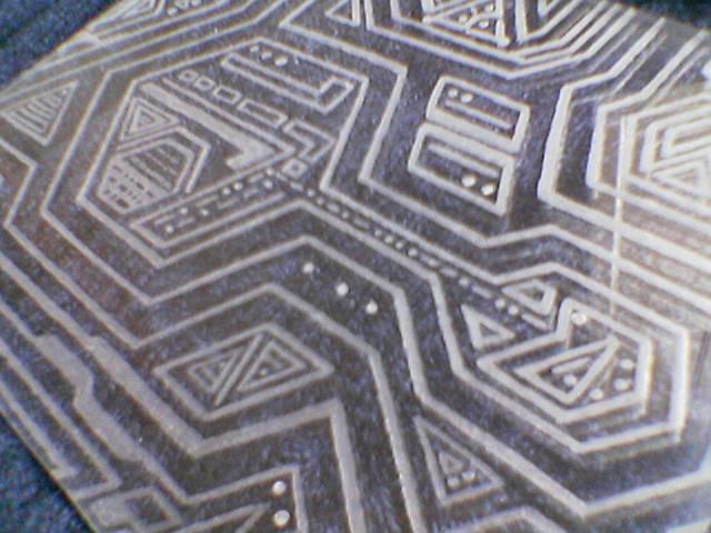
A comparison between raw grooves of the first pass (top in 1st photo, right in 2nd one) and refined grooves of the second pass (bottom in 1st photo, left in 2nd one):
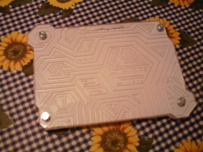
The finished panel:
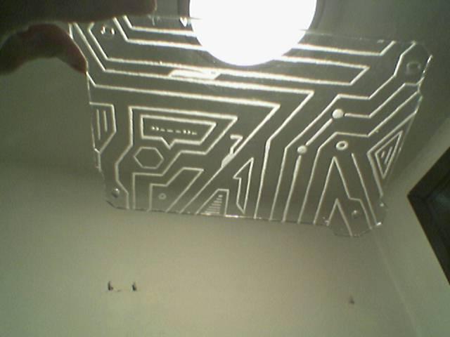

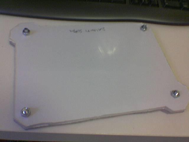
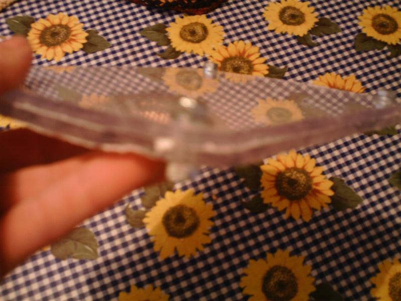
A mounting test:
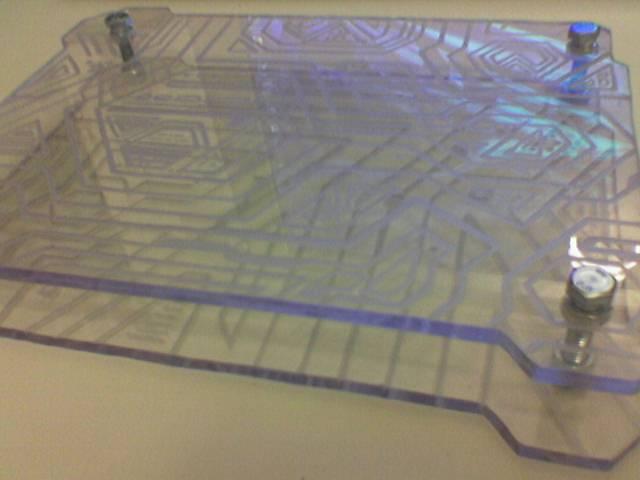
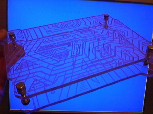
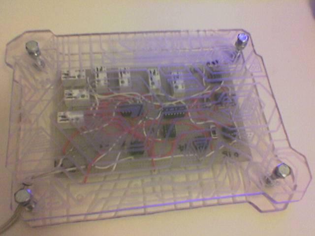
And a test with the circuit inside:
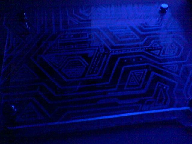
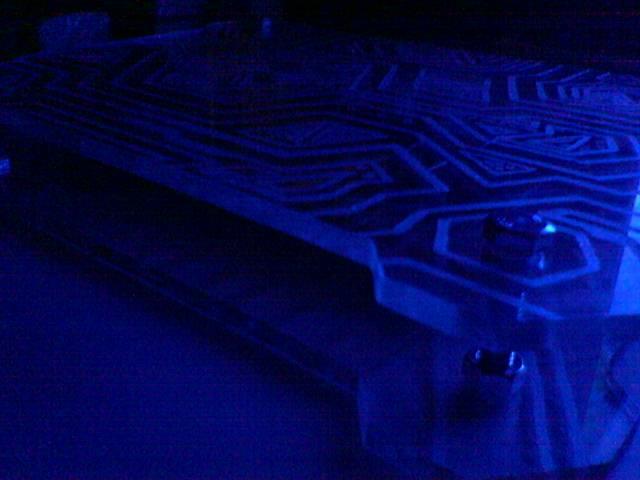
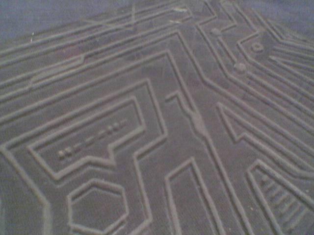
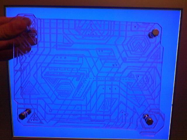
Some lighting tests:
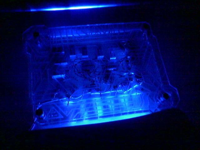
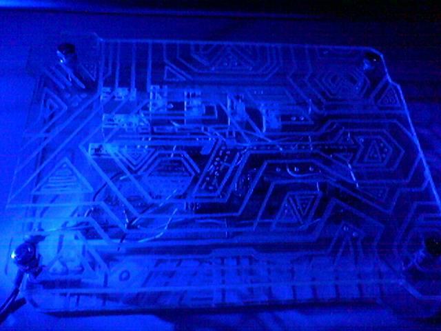
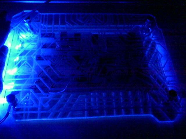
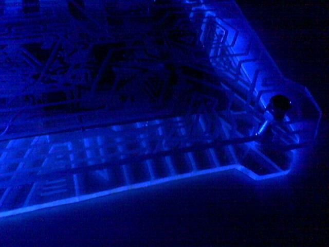
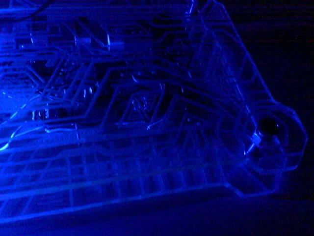
Can you start to see some Tron 2.0 atmosphere? 😀
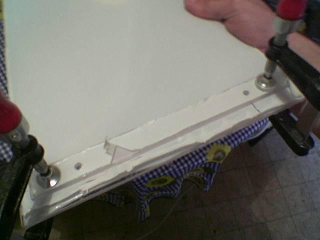
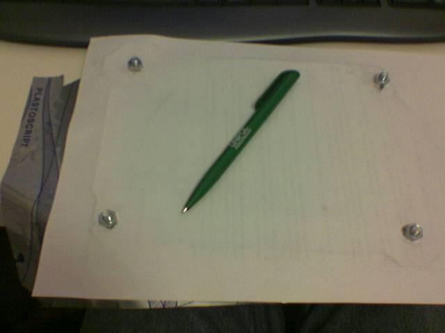
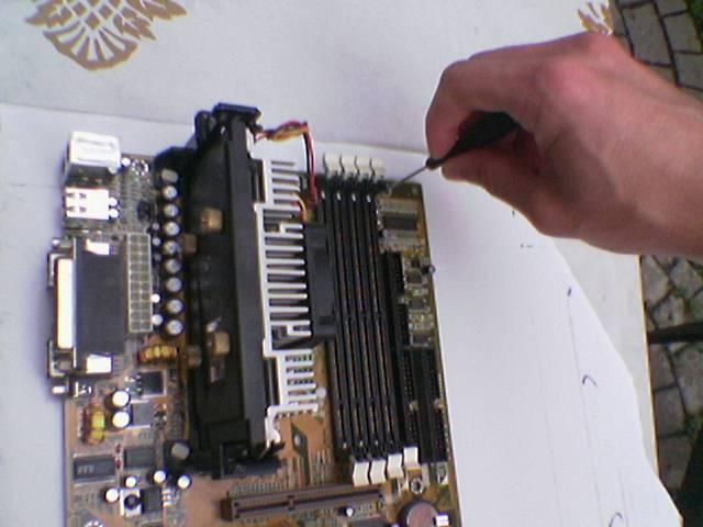
After some measures I traced the first lines for the support of the motherboard:
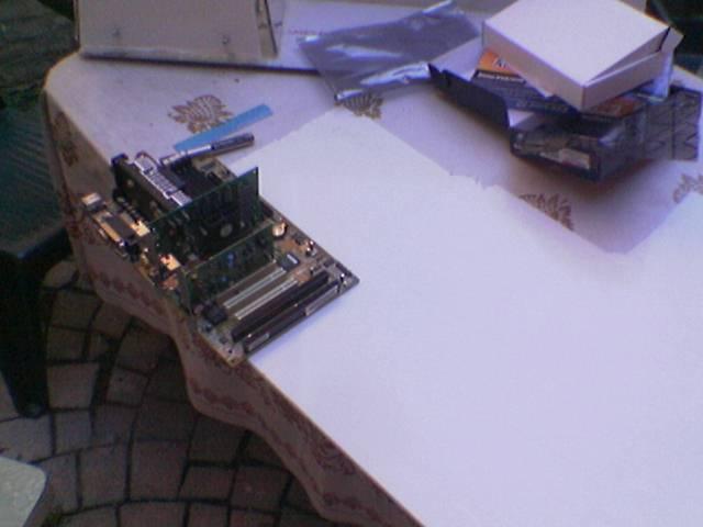
in this photo I did a test to see how much space to leave on the panel to fold it:
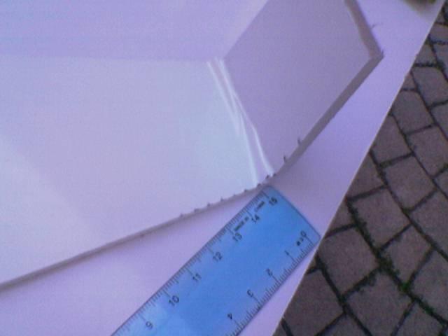
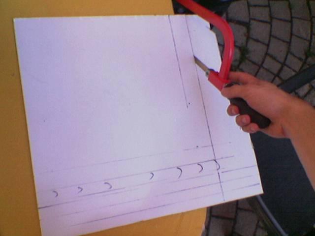
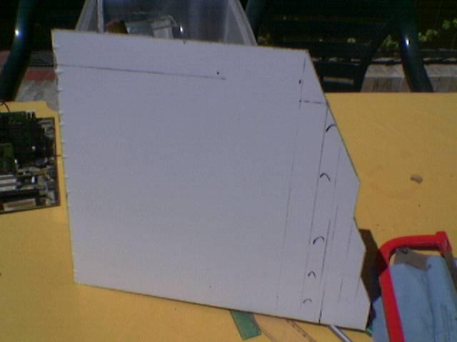
Taken all the appropriate measures I started to cut the panel:
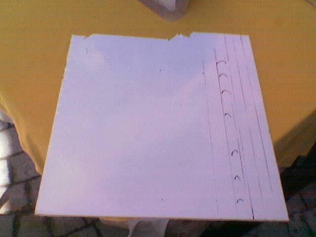
The raw panel cut:
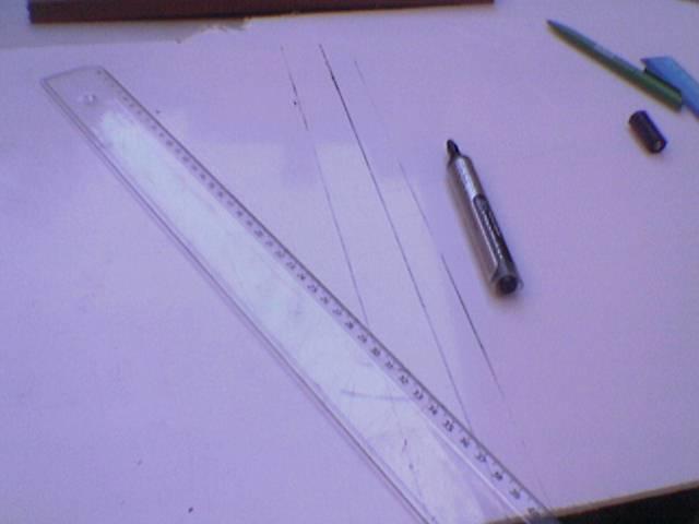
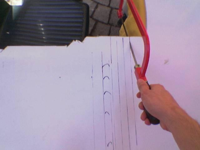
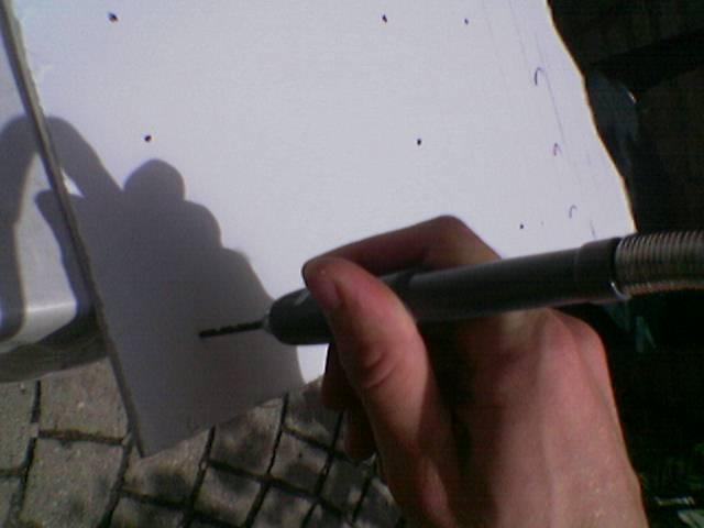
I begin to draw the lines of the left edge (some are oblique to 60 degrees):
I start to cut them…

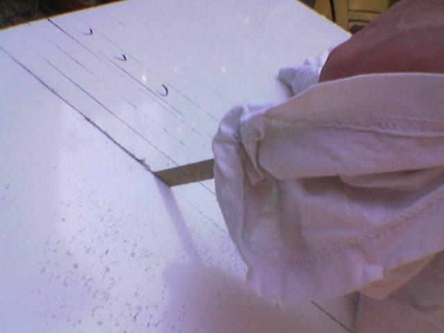
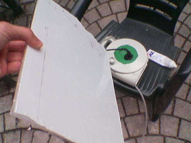
The panel cut:
Then I polished the edges:
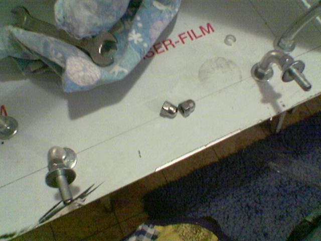
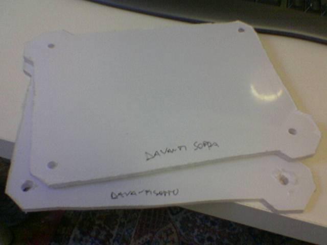
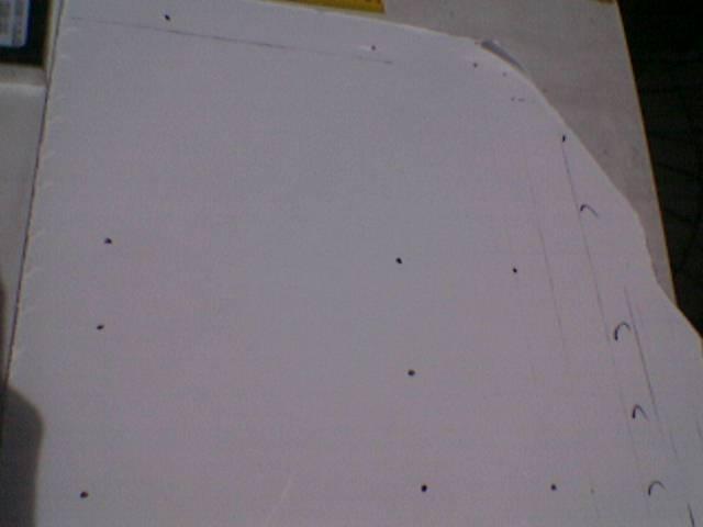
I mark the position of the holes for the motherboard (both atx and microatx)
The position of all the holes:
I begin to drill the holes:
Done: