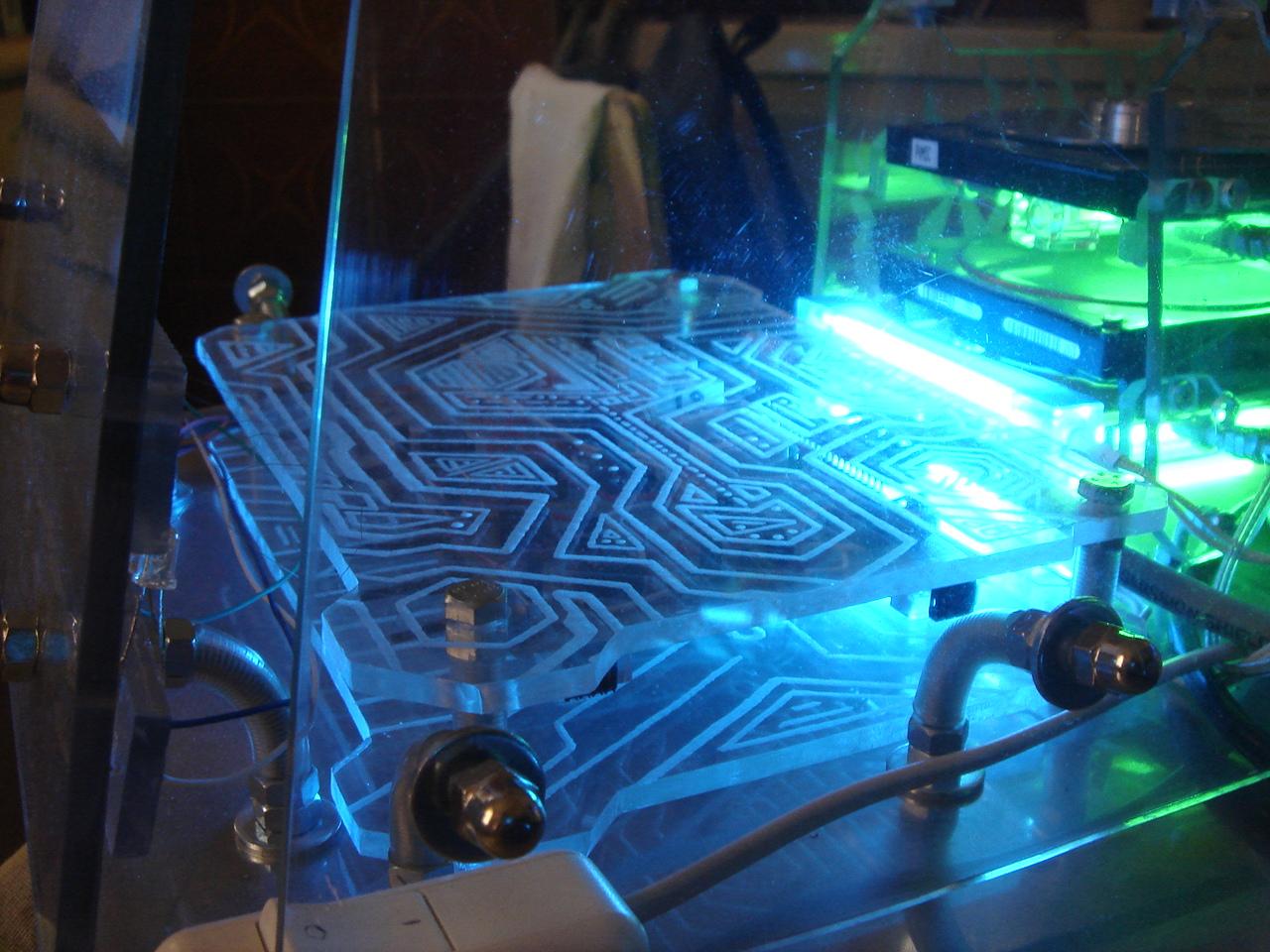
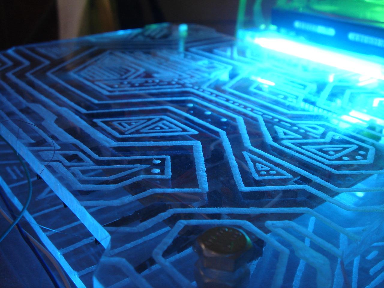
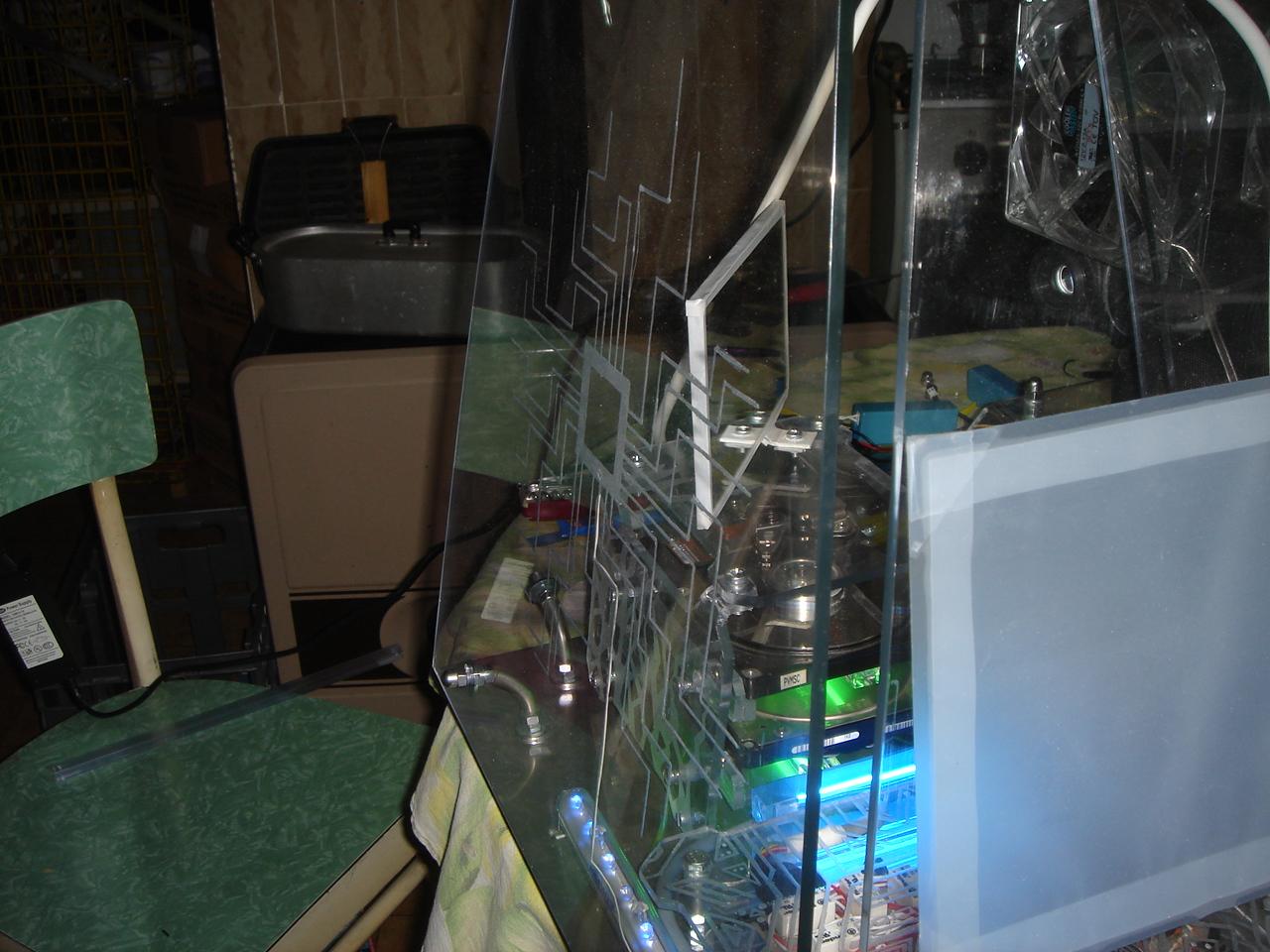
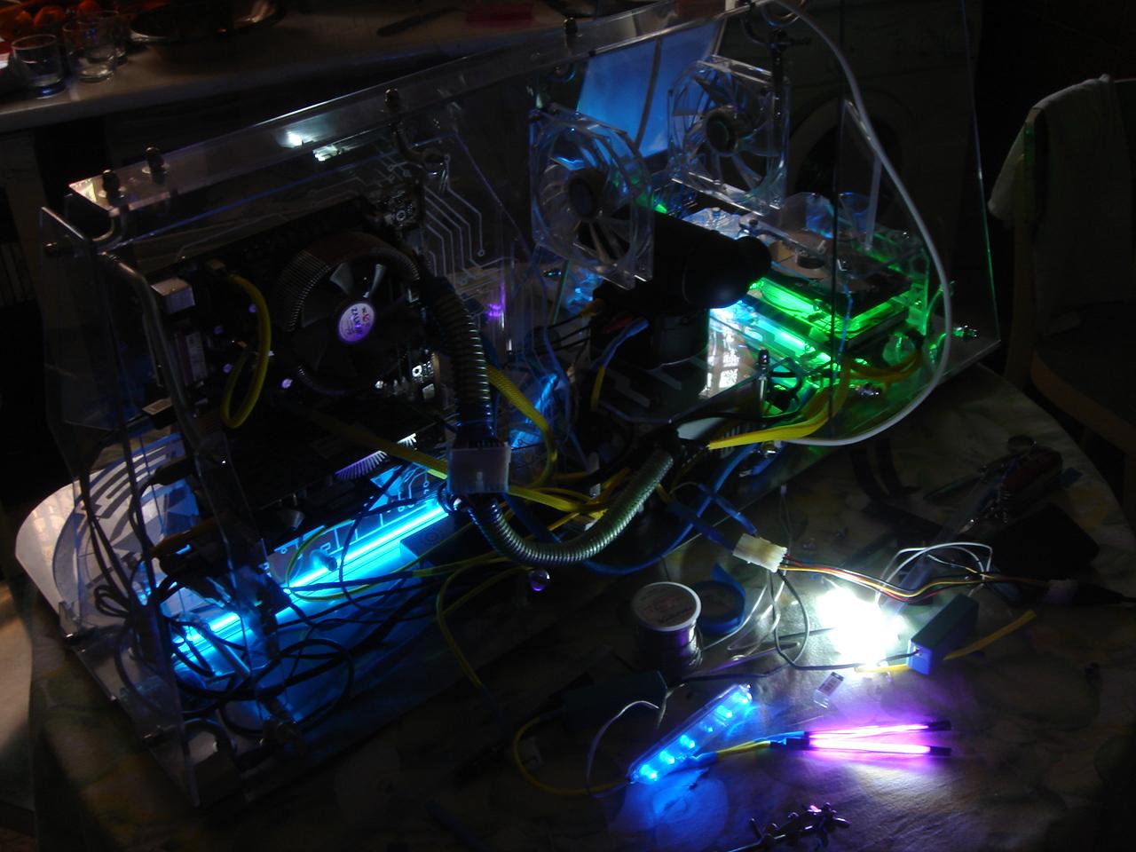
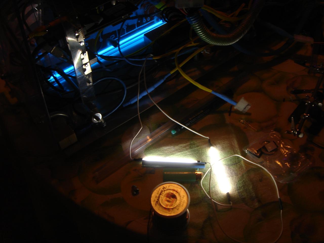
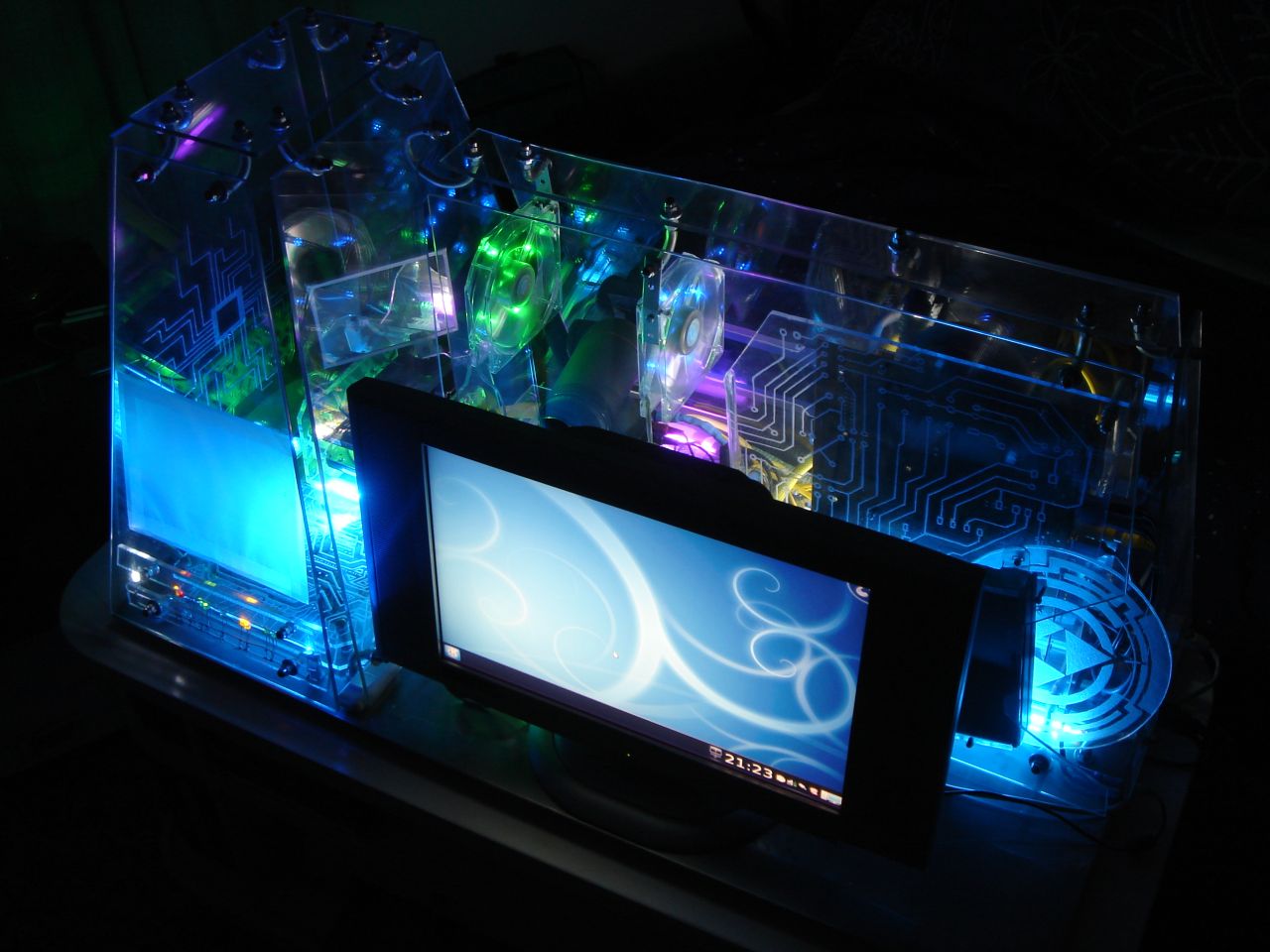
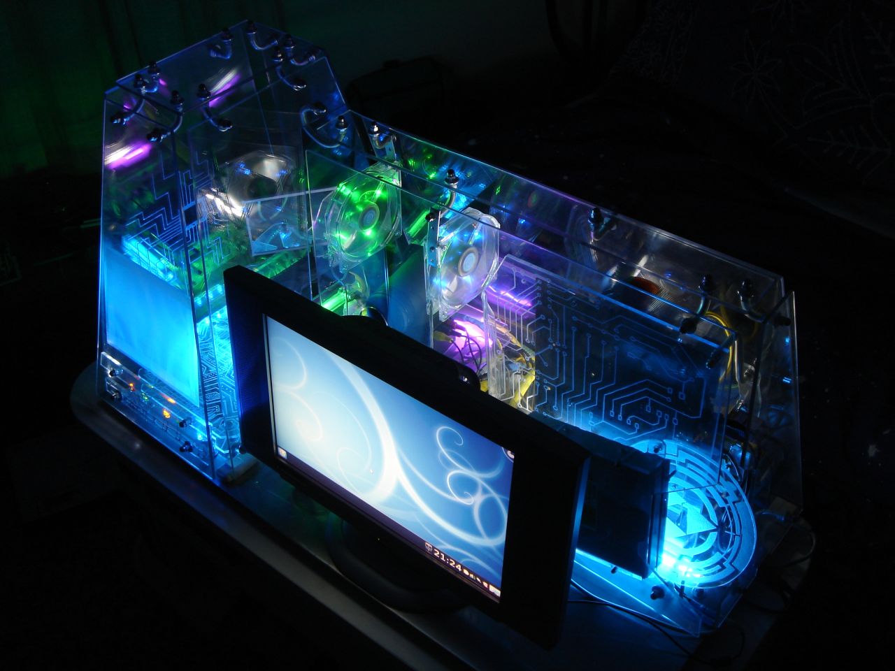
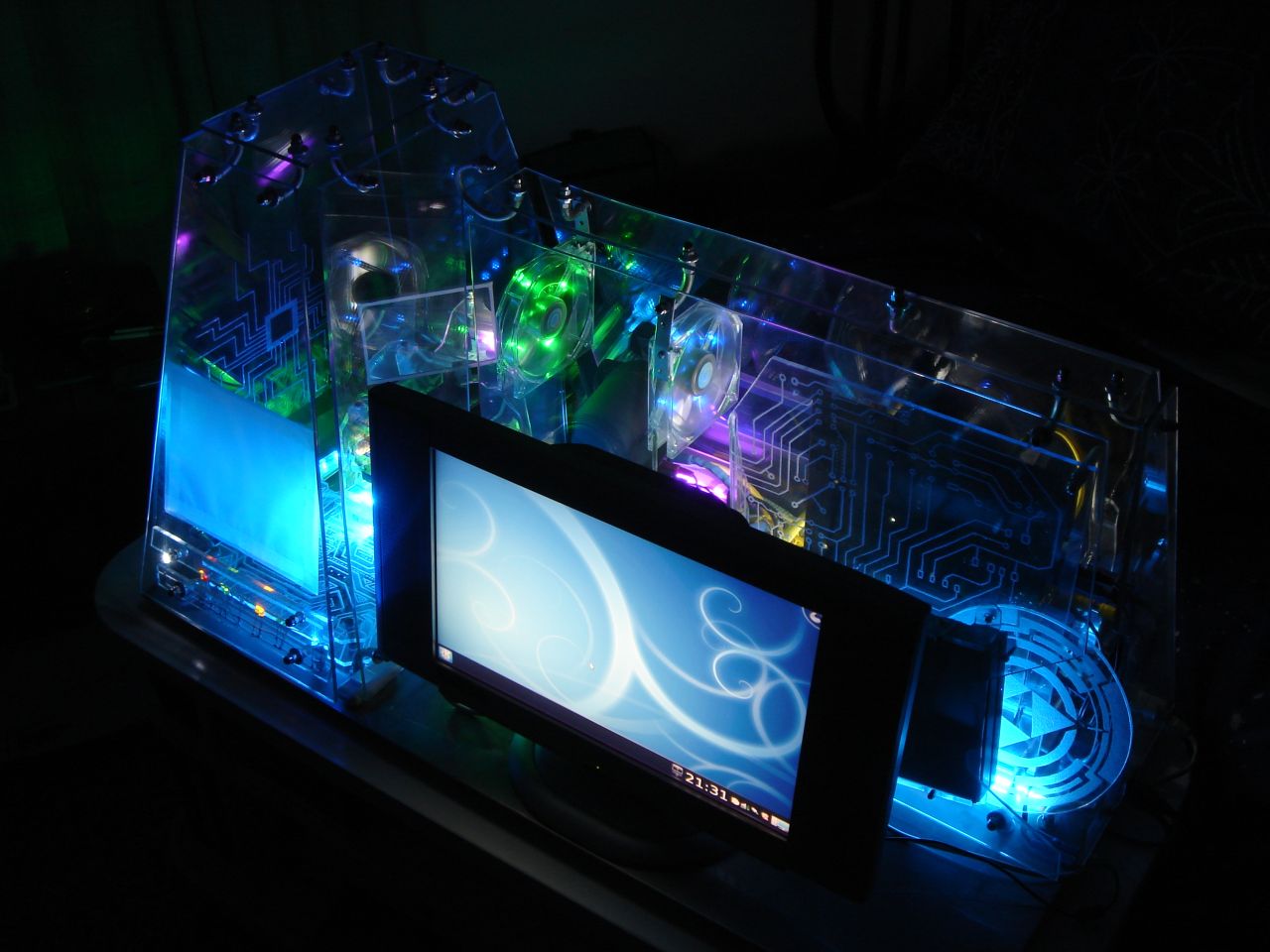
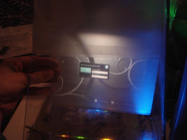
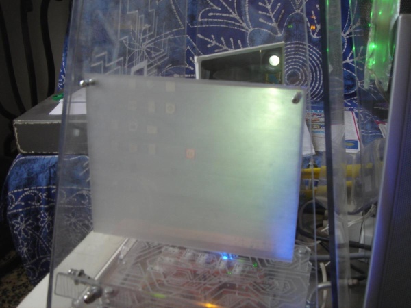
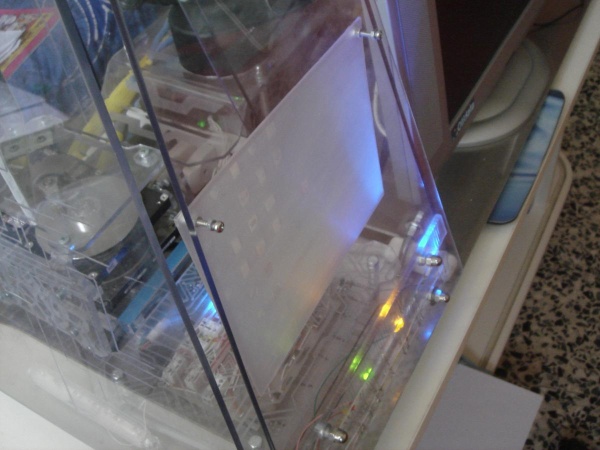
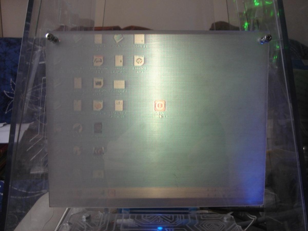
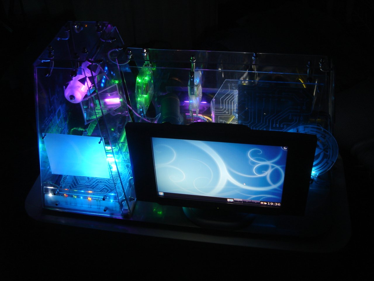
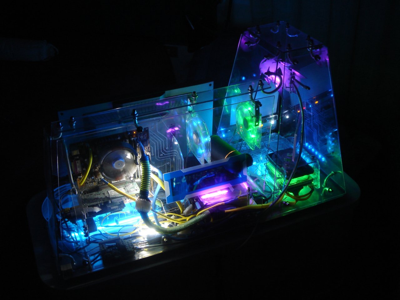
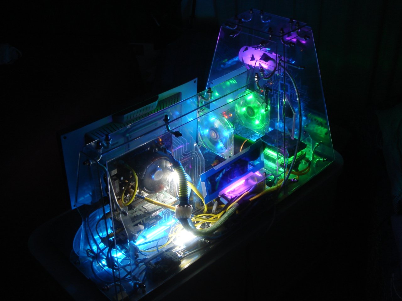
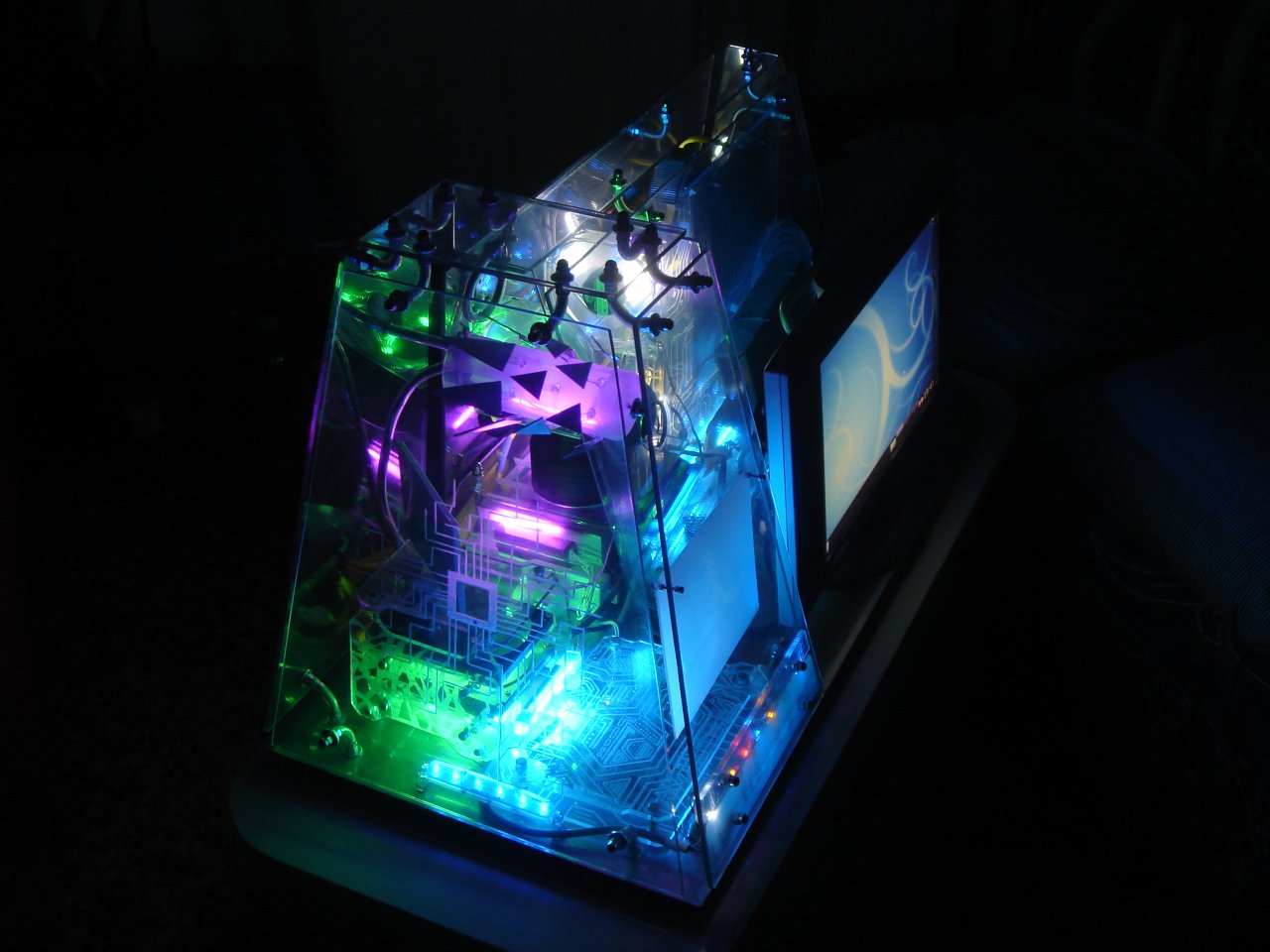
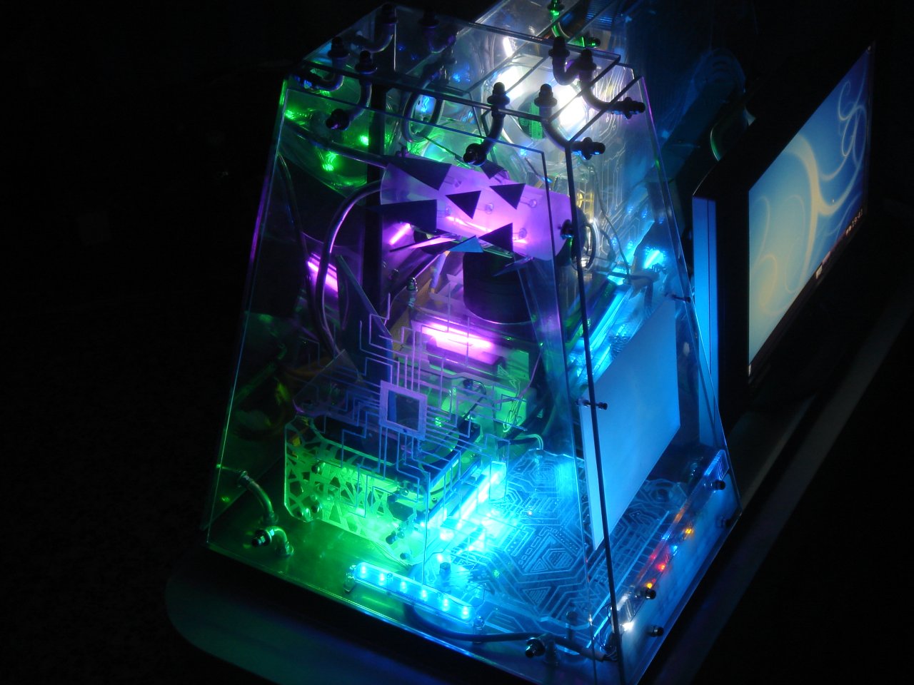
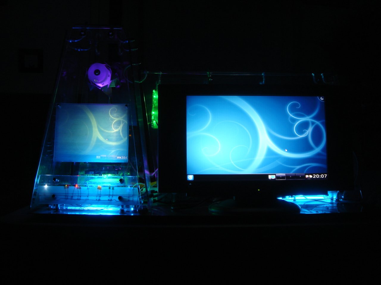
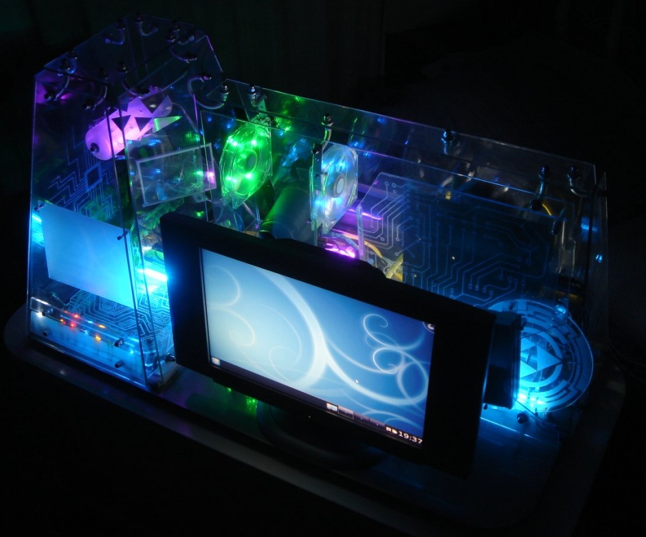
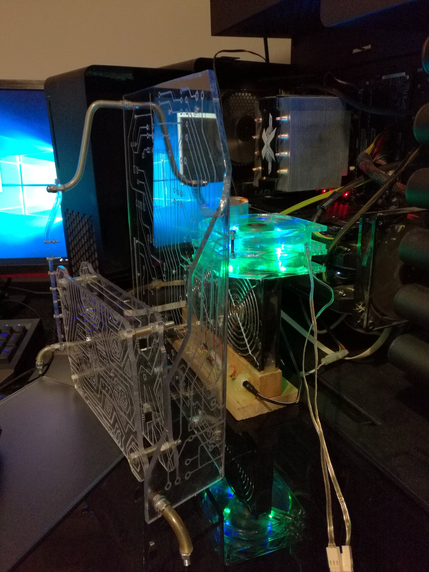
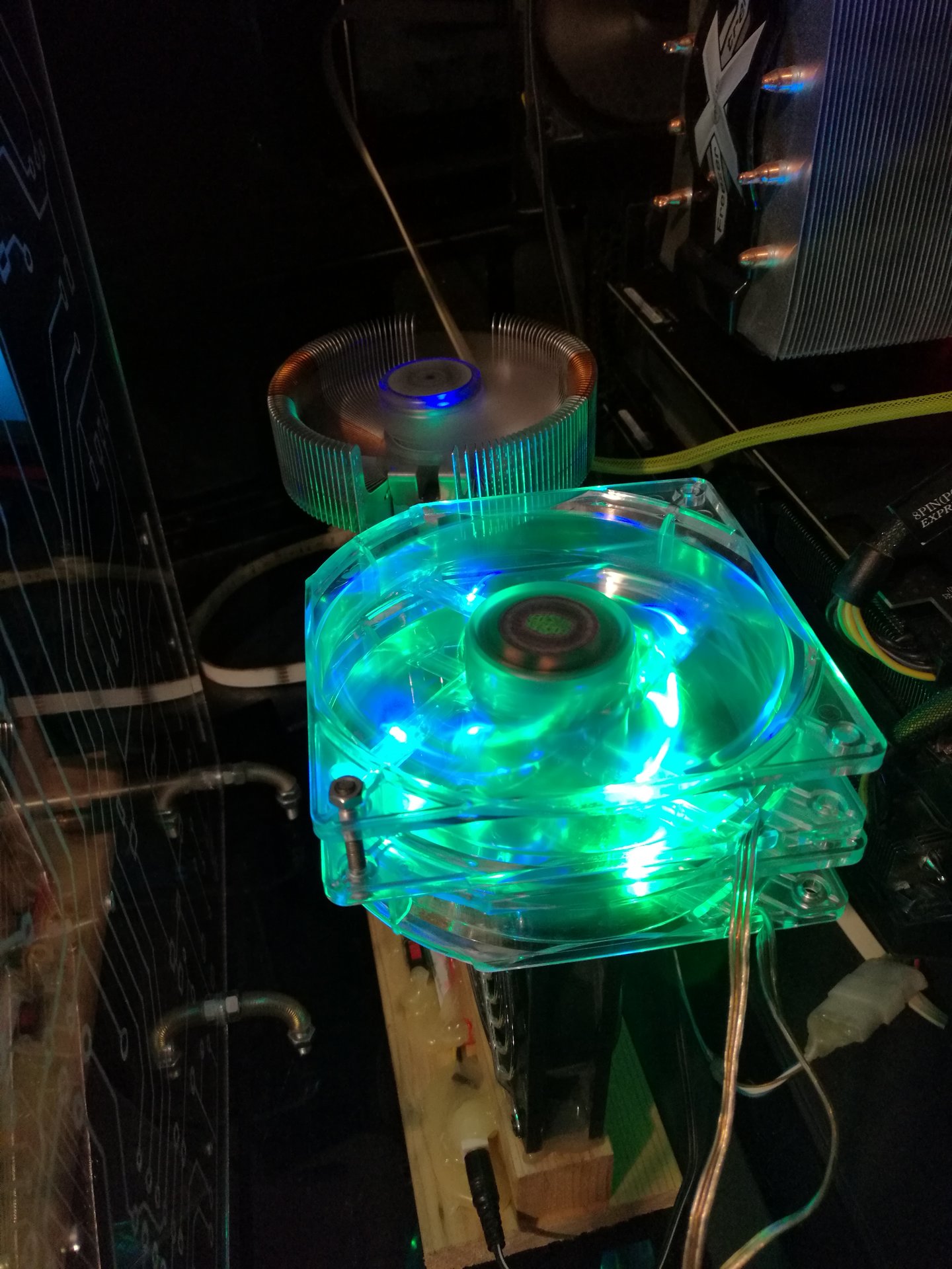
Some pics in the dark, with the projector turned on, showing the secondary monitor:
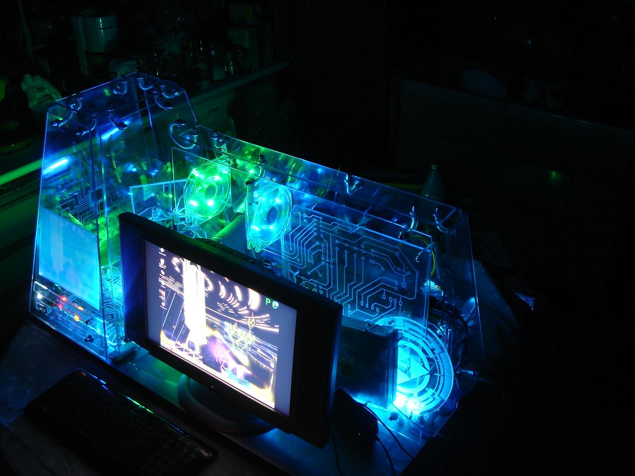
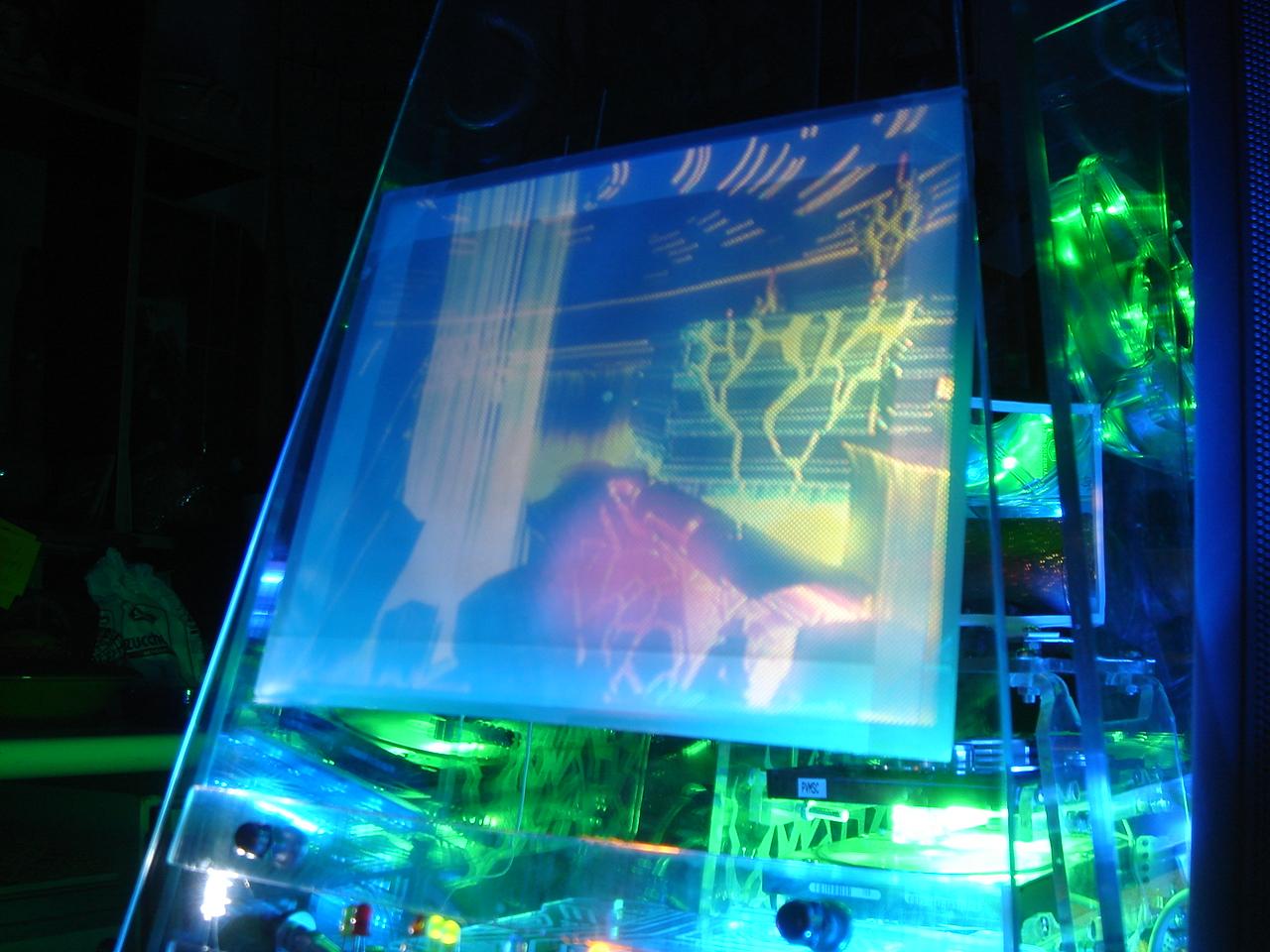
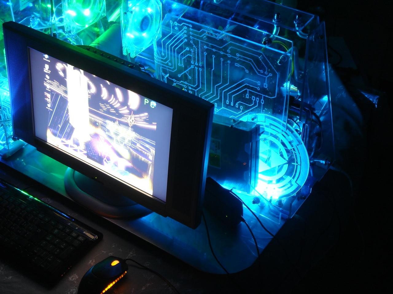
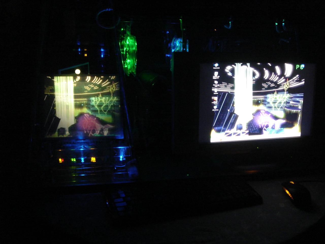
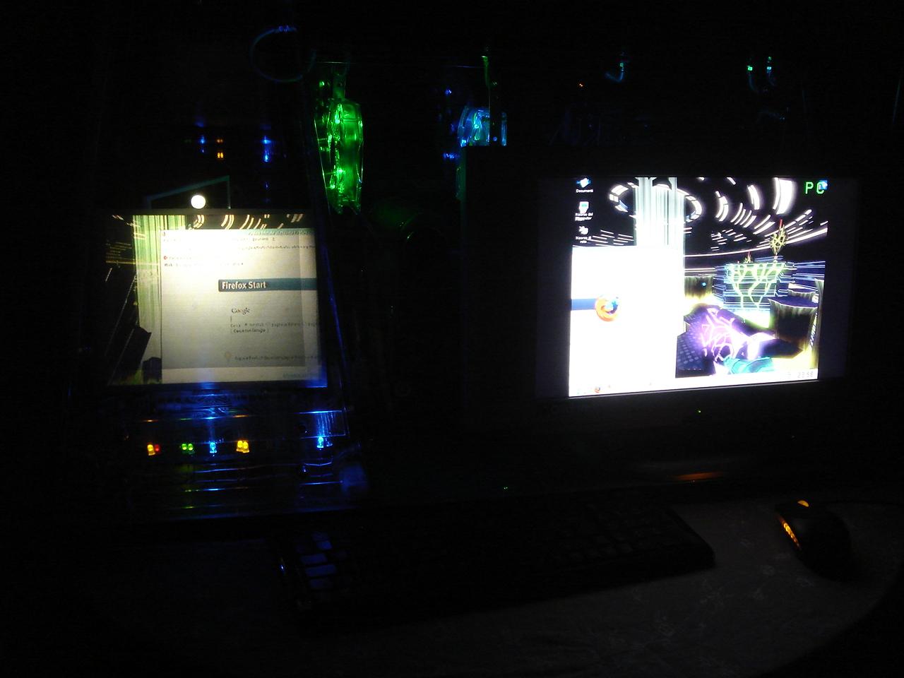
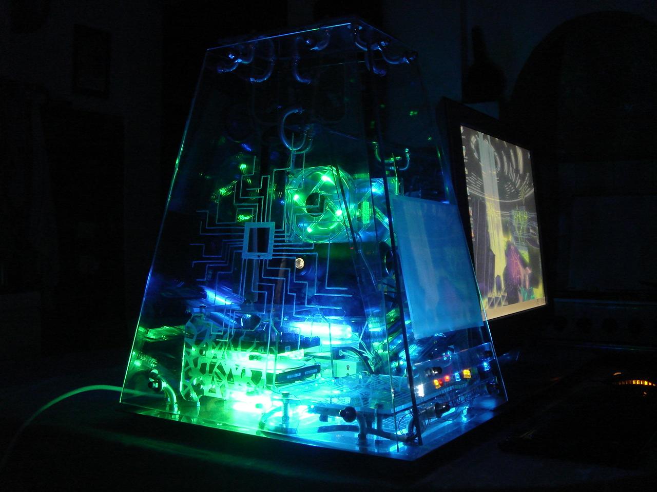
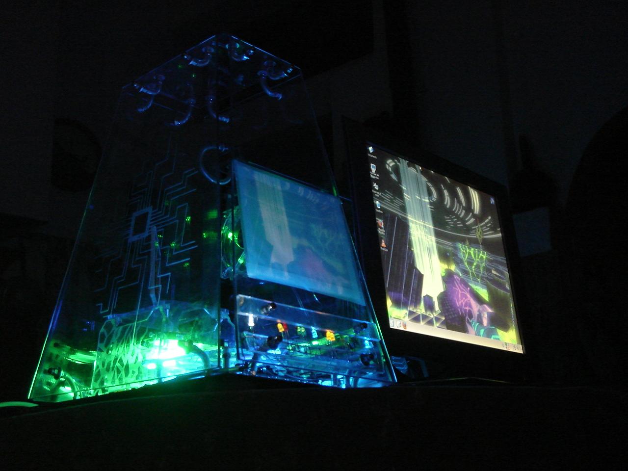
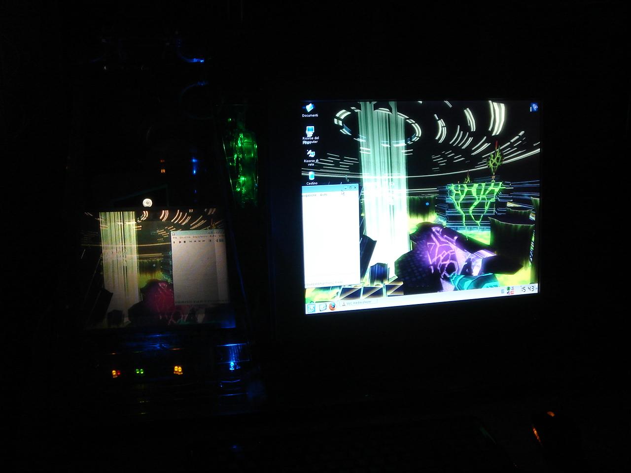
Some pics in the dark, with the projector turned on, showing the secondary monitor:
This is the video that shows the main features of the case:
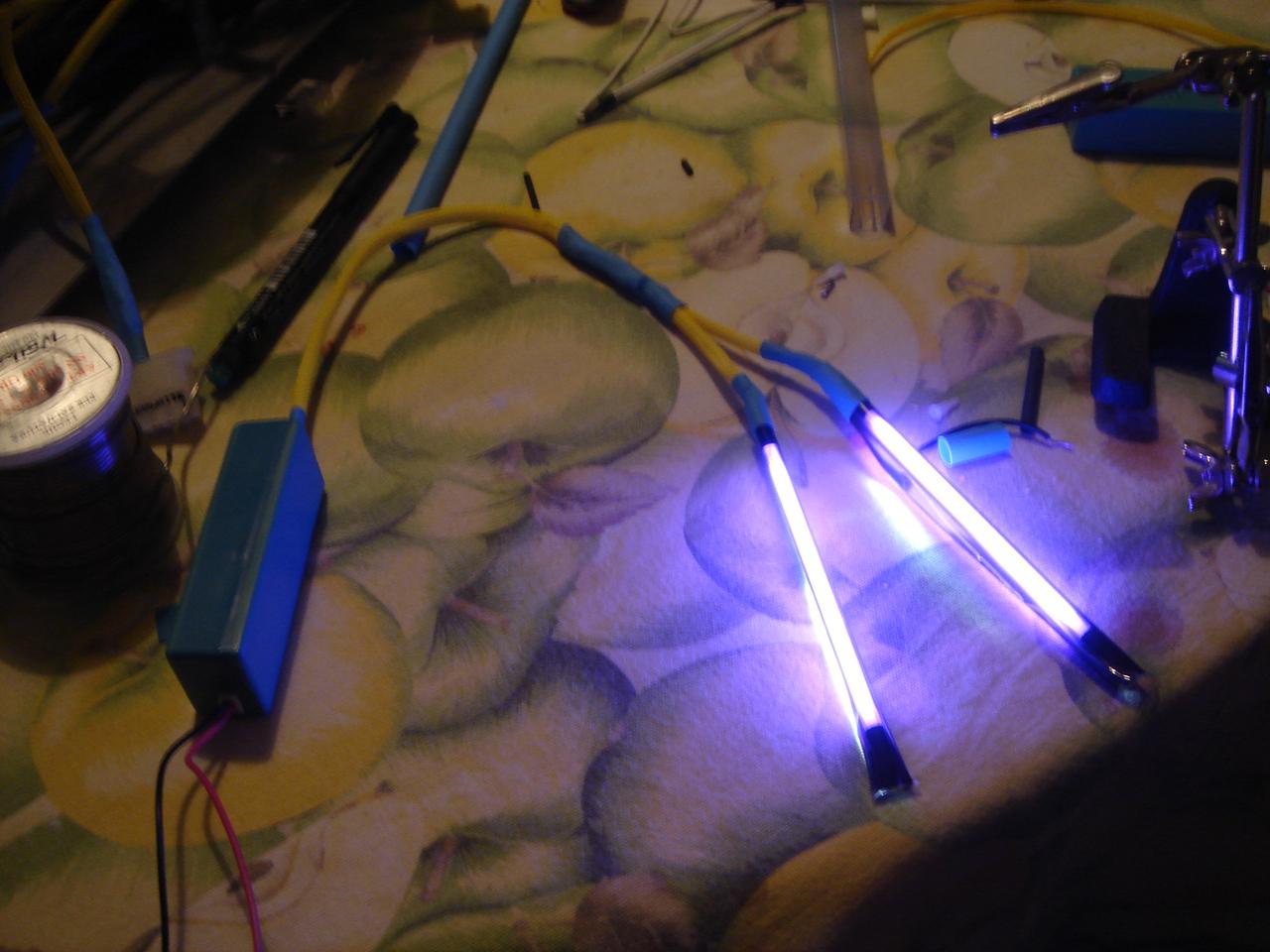
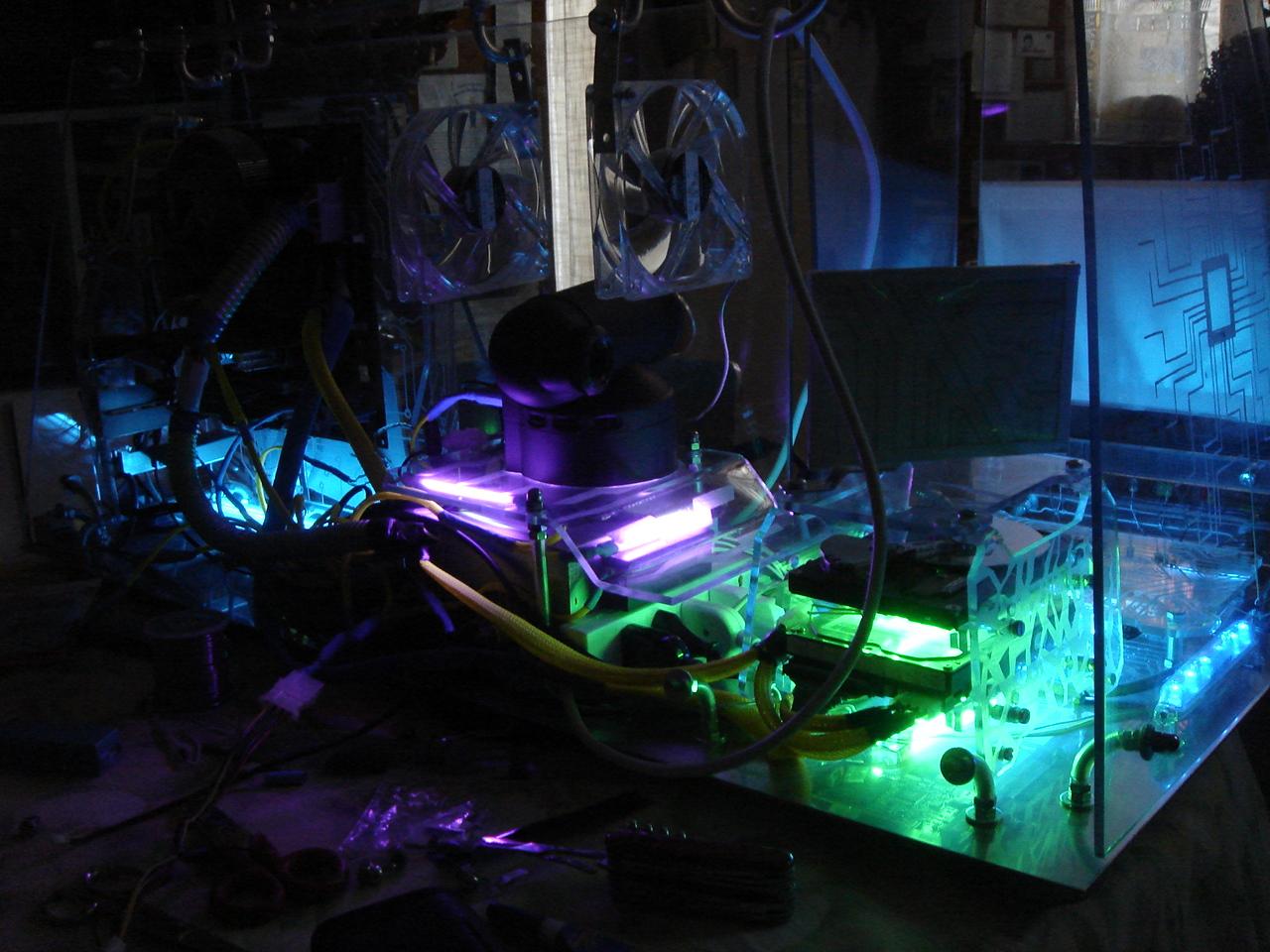
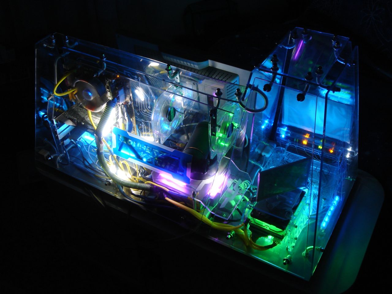
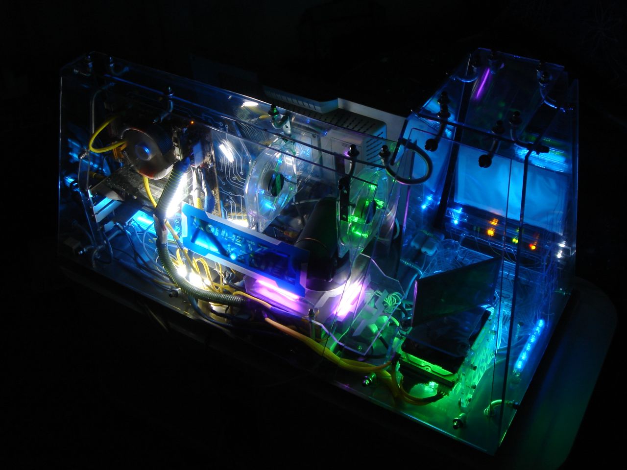
I thought that the case was not enough enlighted, so I added 4 other cold cathodes: two white and two purple.
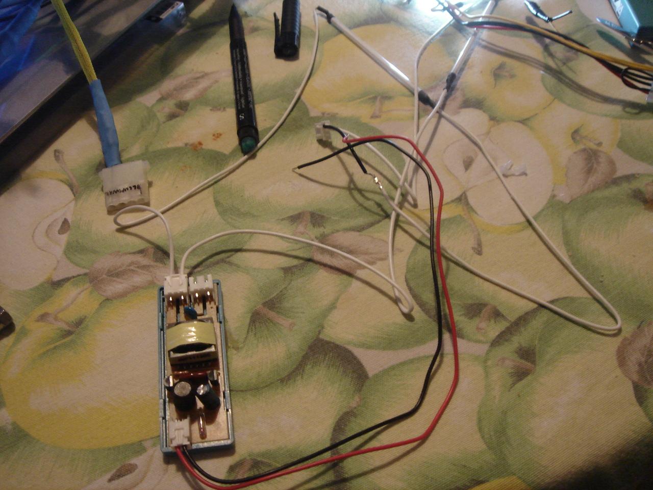
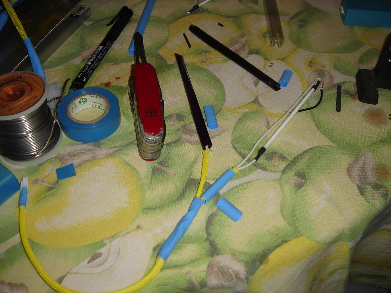
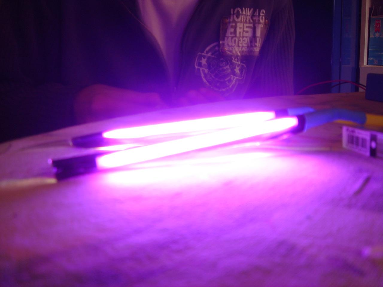
I have made the purple lights by myself, using white lights and a film of purple chromatic filter:
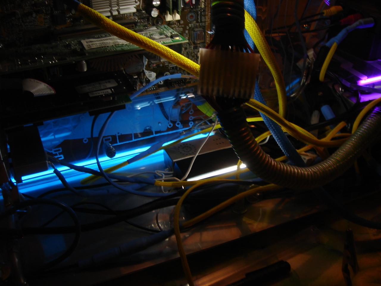
First I moved another blue neon on the upper part of circuit encasing (so it is enlighted by 2 neons):
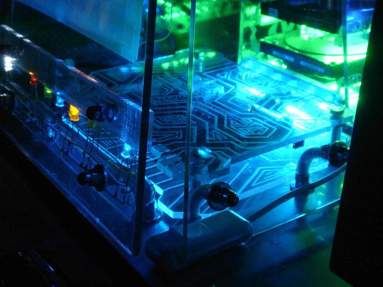
Then I put the 6 blue led structure to better light the proximity sensor engraving:
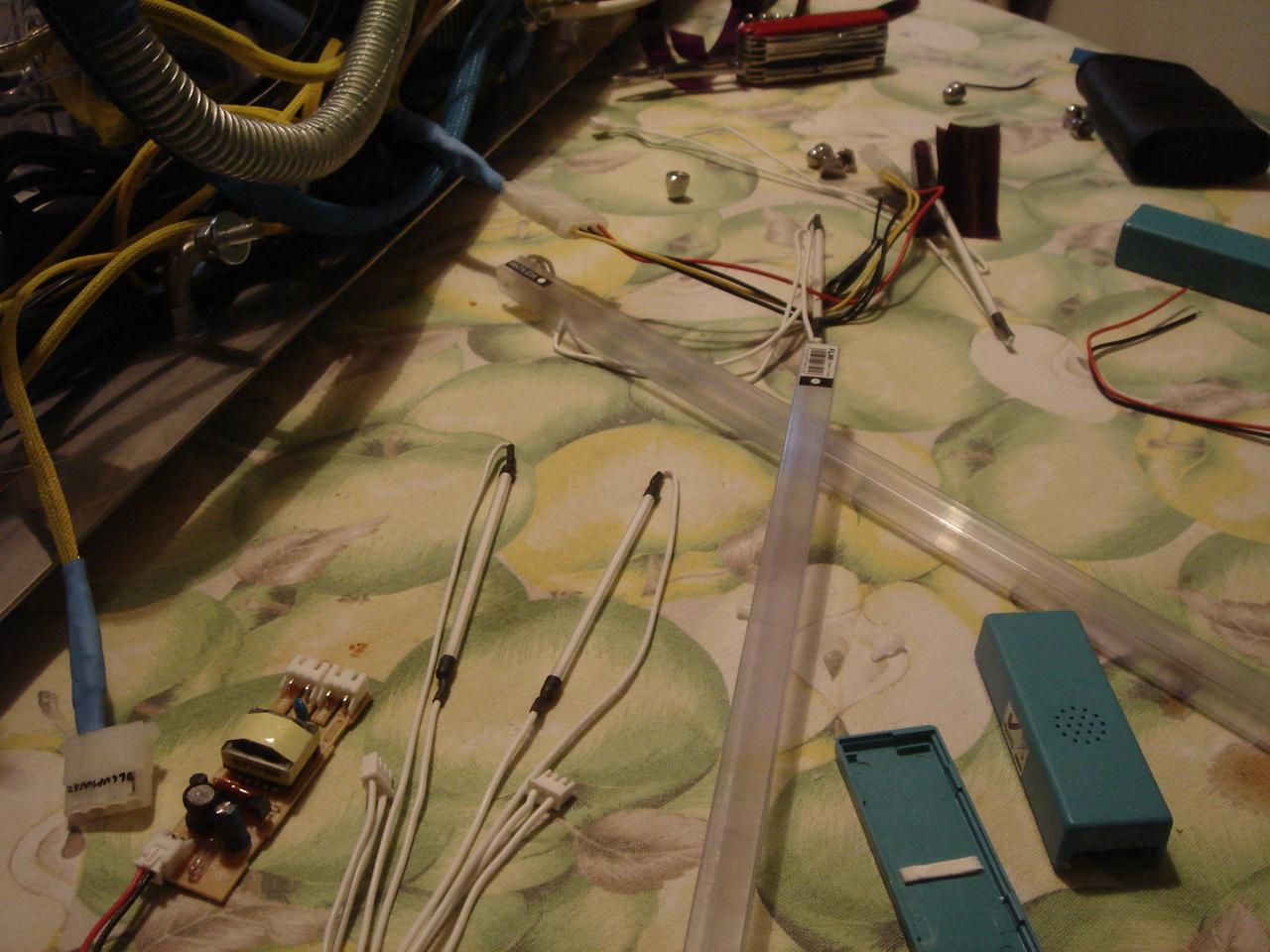
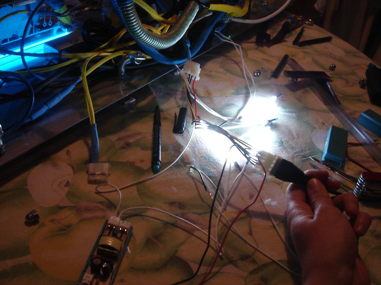
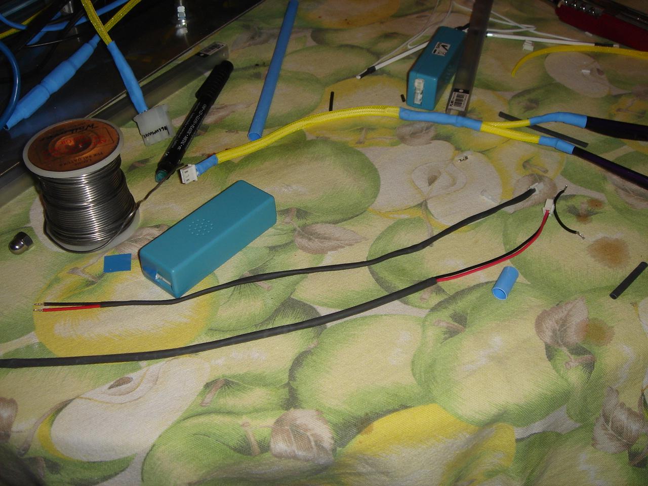
Here I complete the wiring of the two couples of neons:
And here I put the purple neons under the PSU cover:
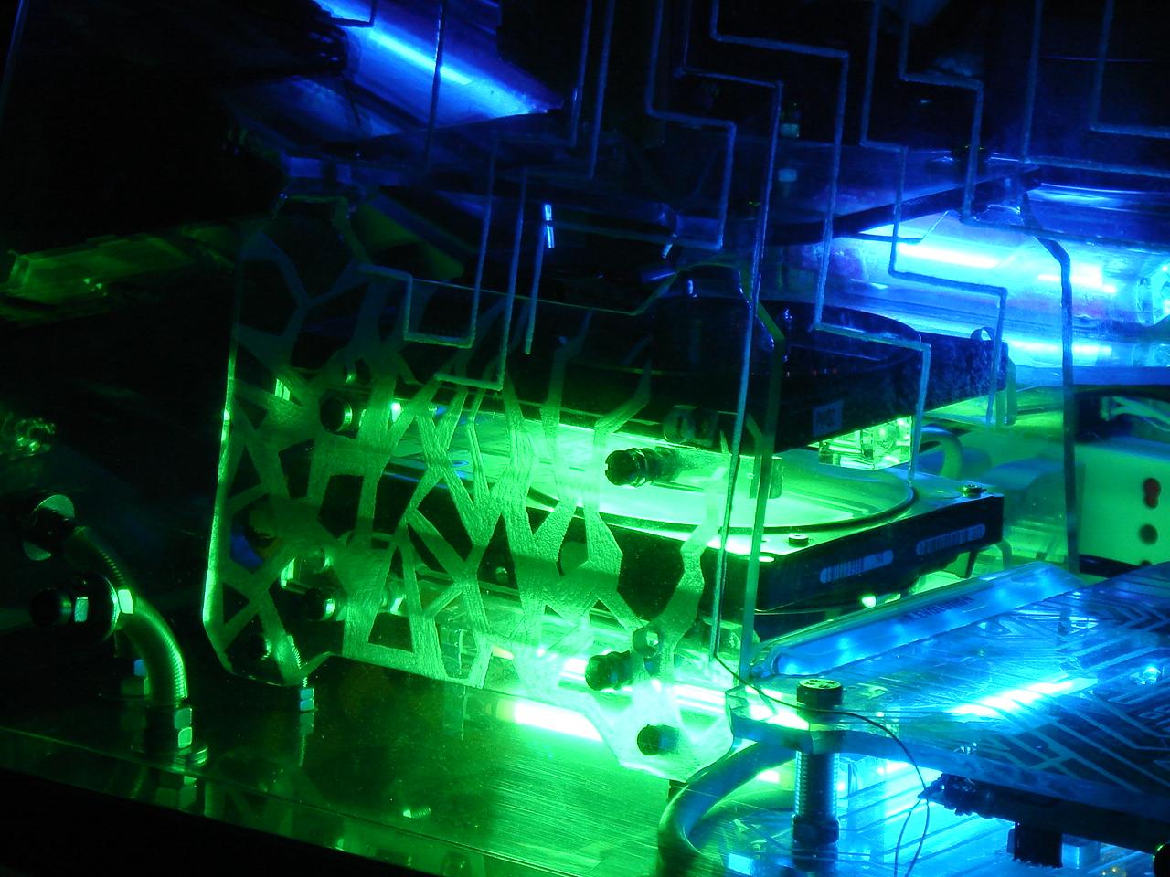
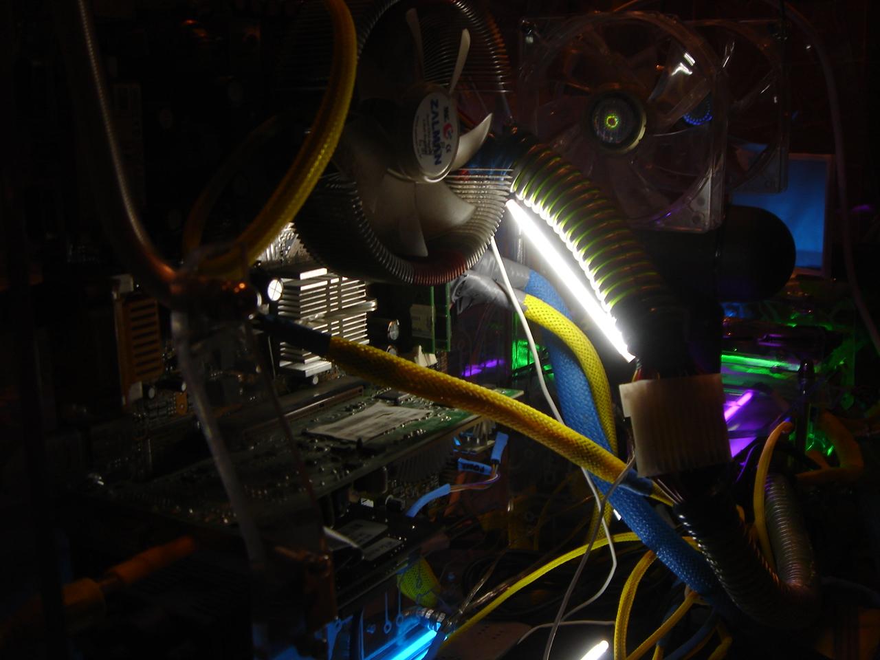
The white neons must light the motherboard:
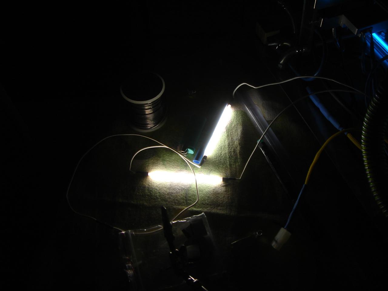
One of them lights the motherboard from below:
The other one is hidden behind the big PSU-motherboard cable, so it lights the upper part of the motherboard and the “acid green” transparent plastic wire that spires around the cable’s tube:
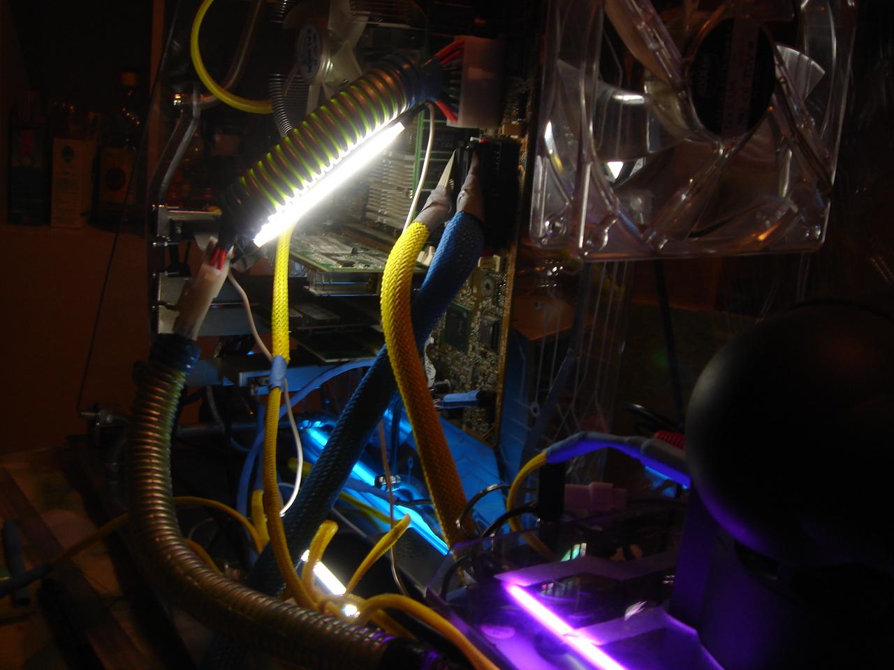
This is the effect on the cable’s tube:
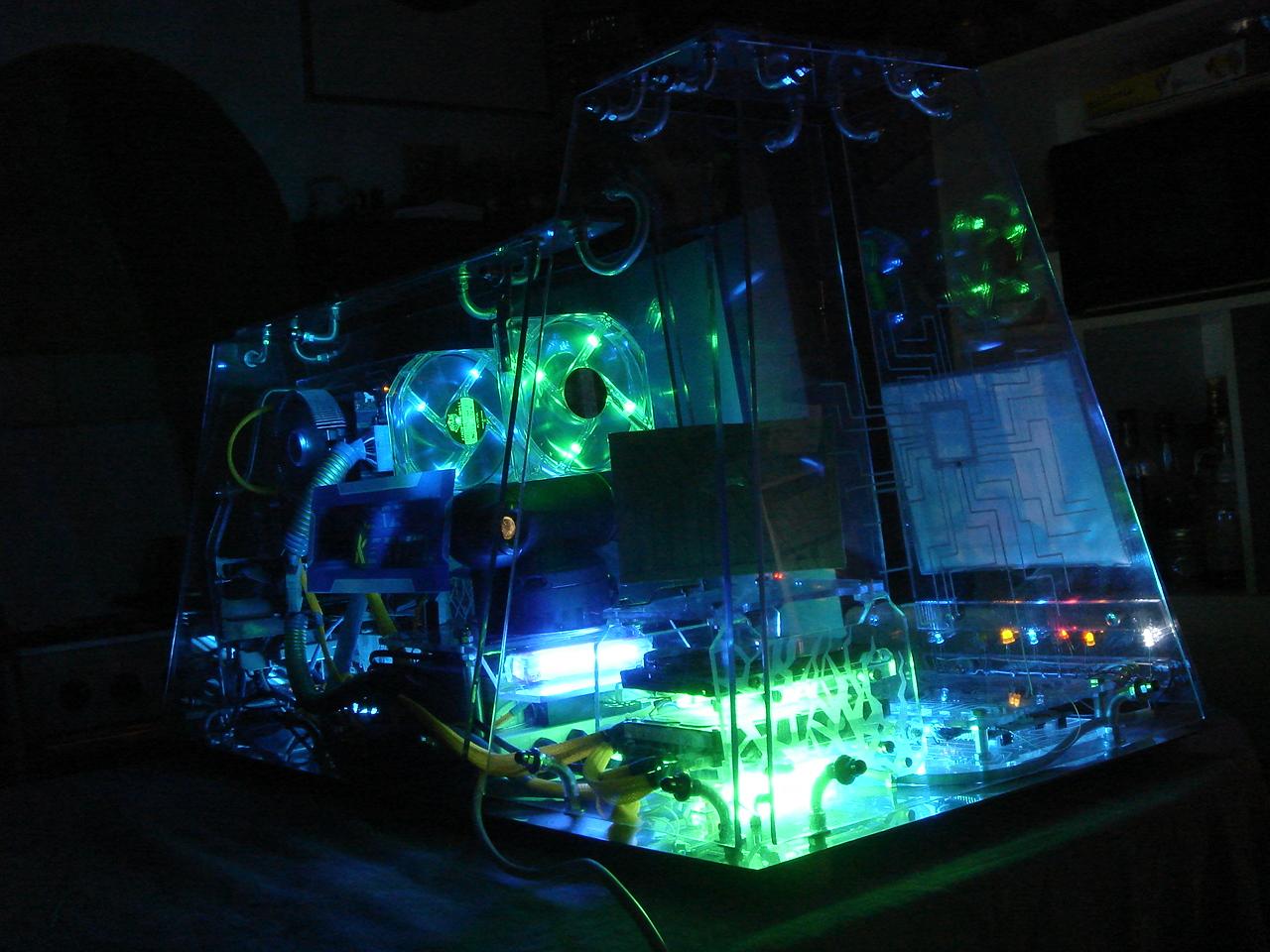
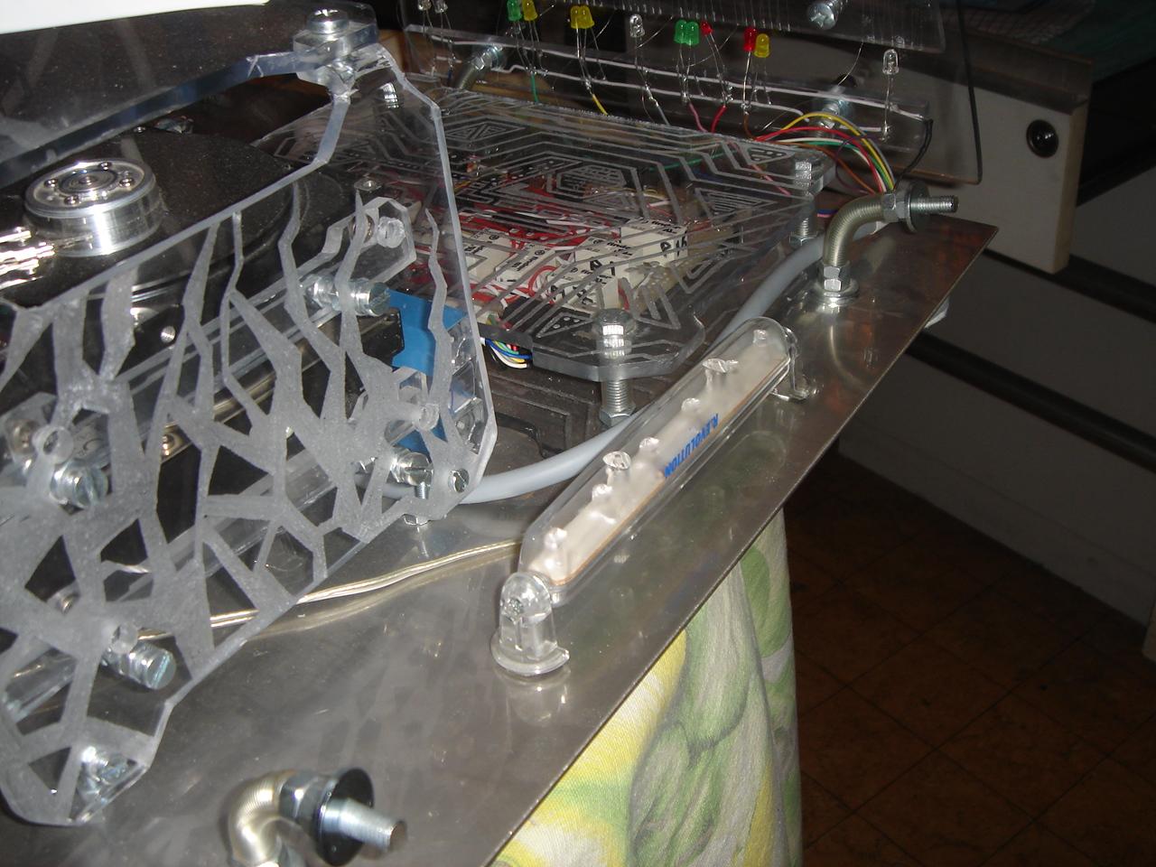
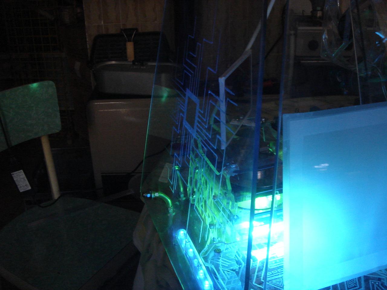
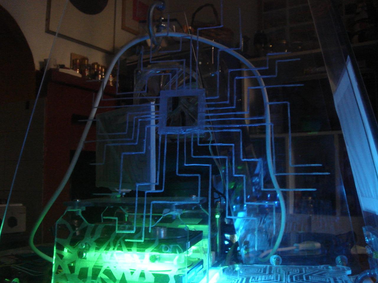
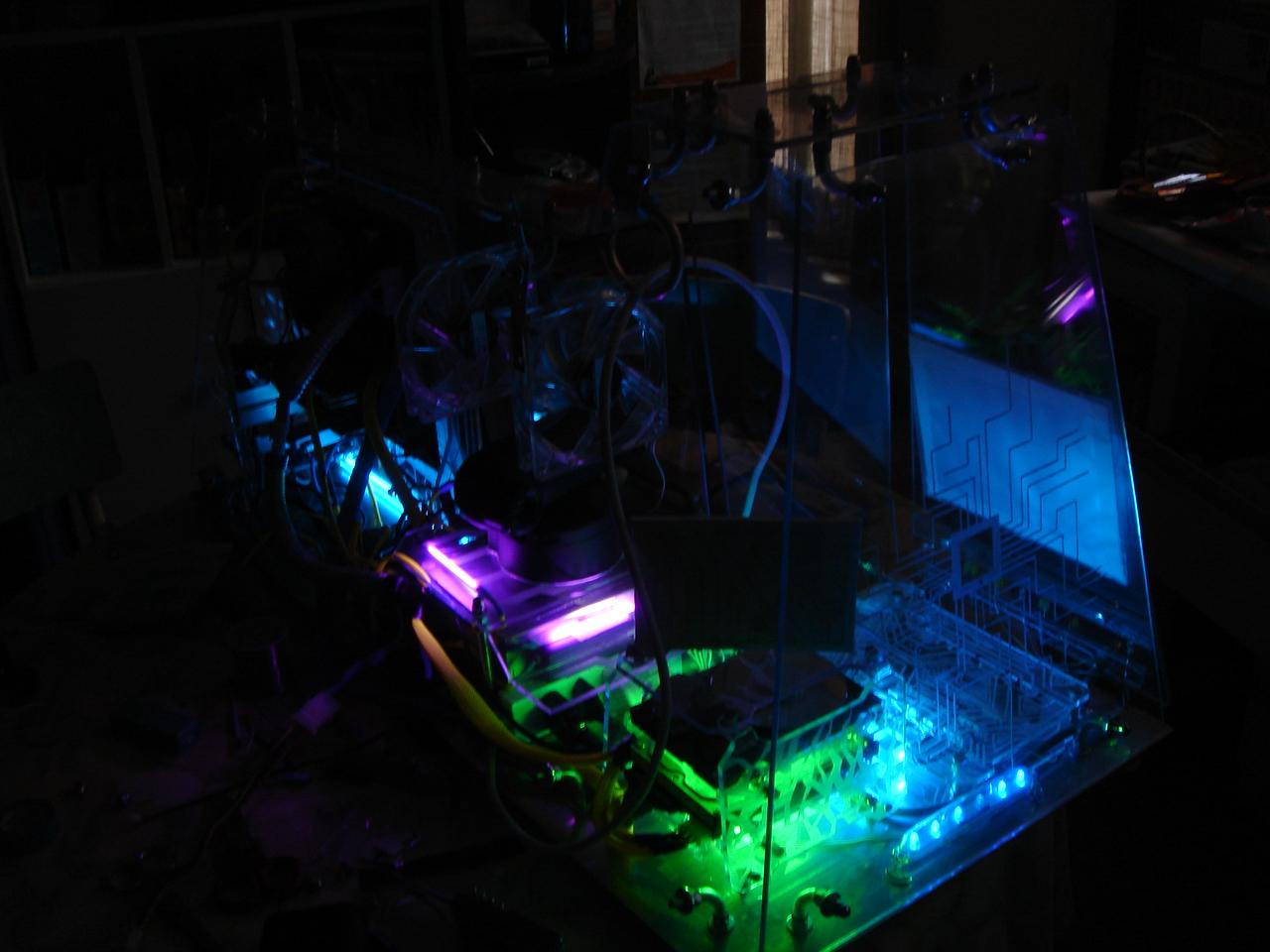
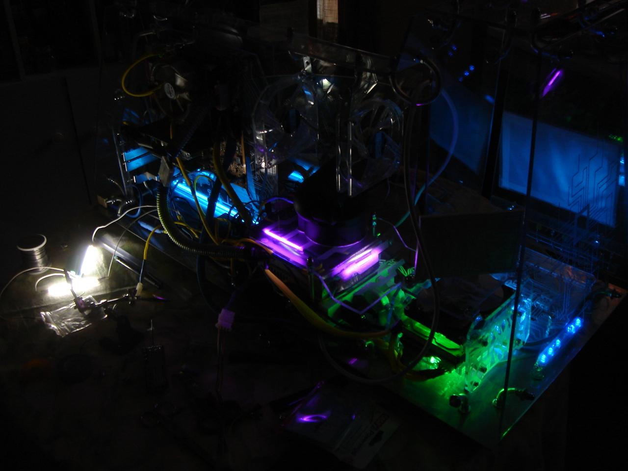
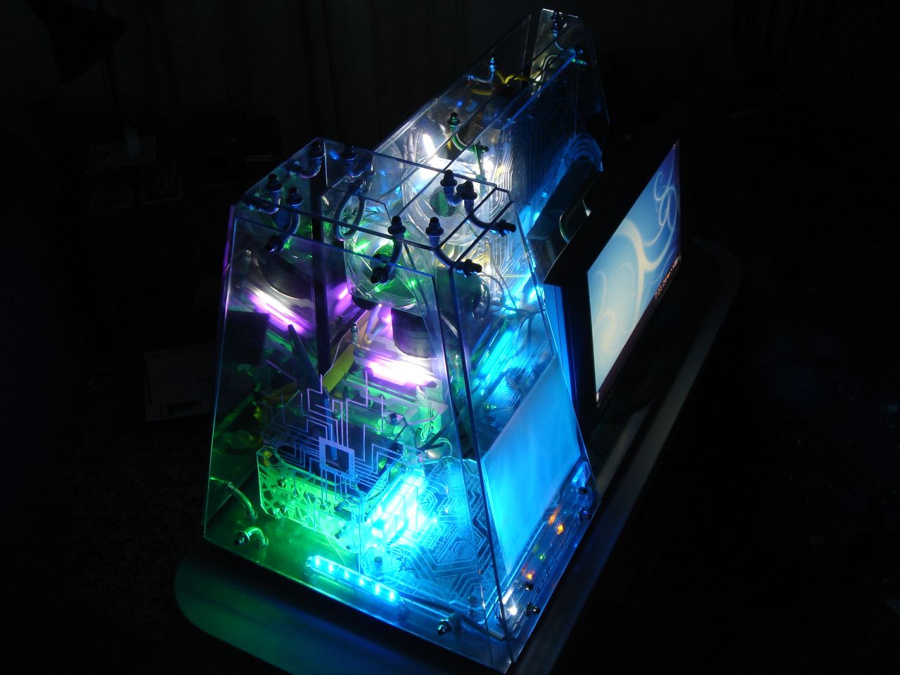
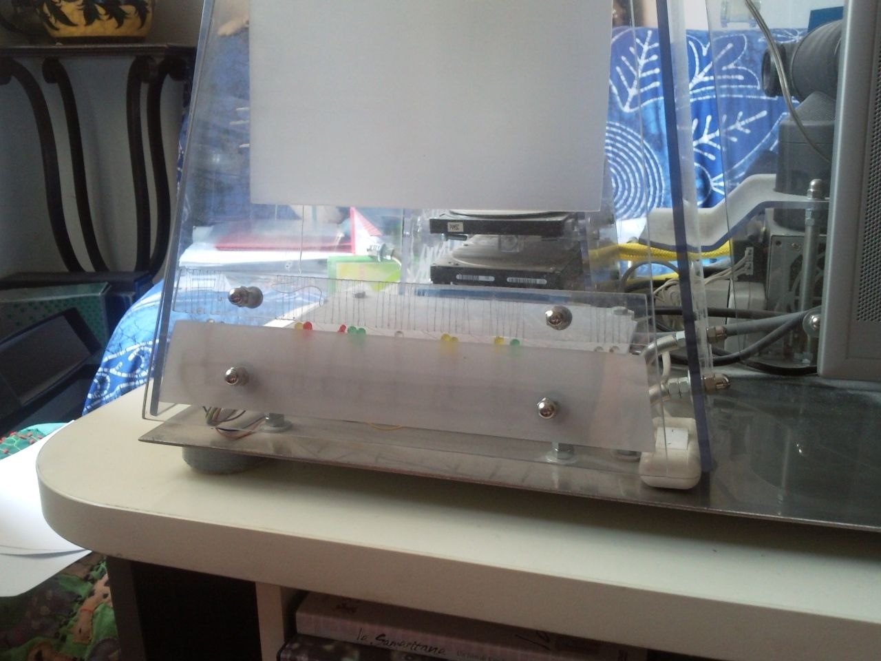
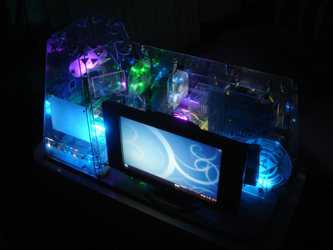
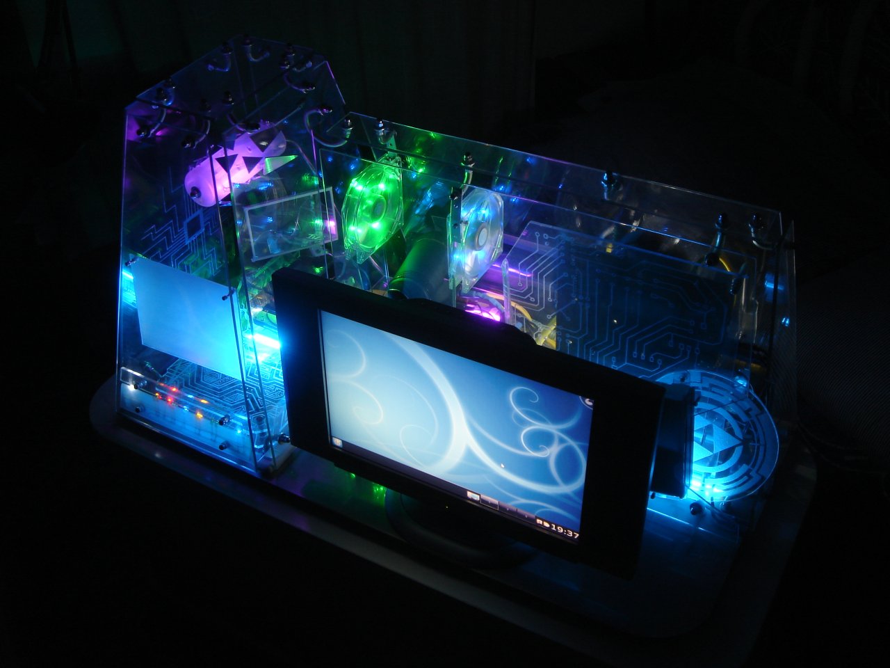
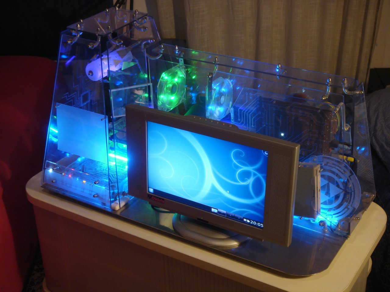
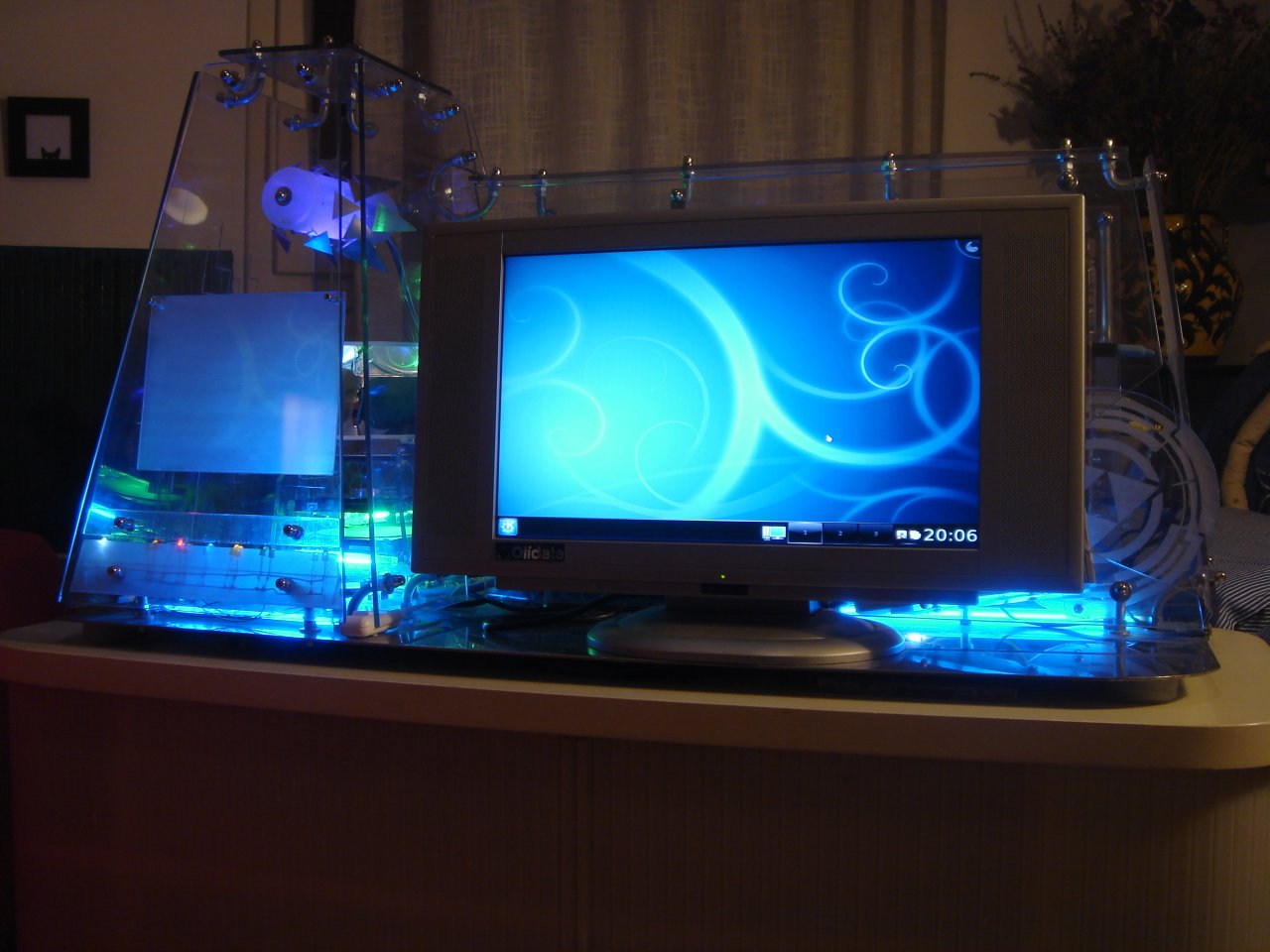
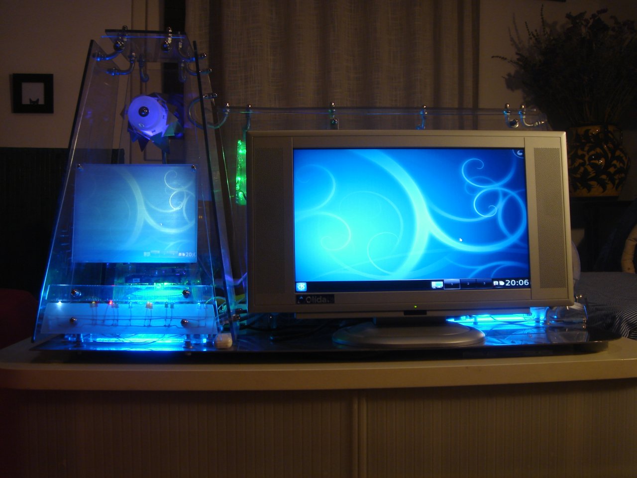
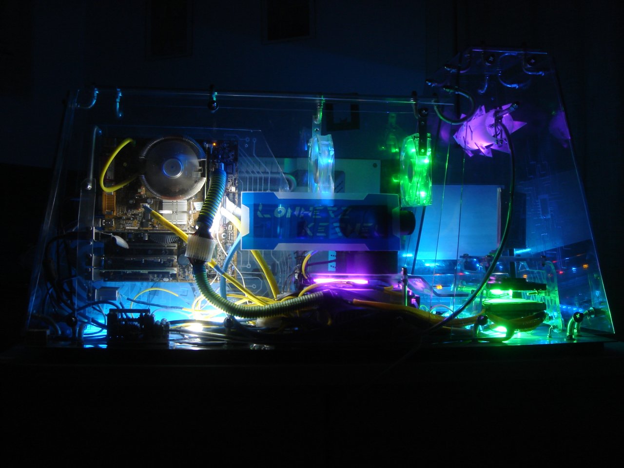
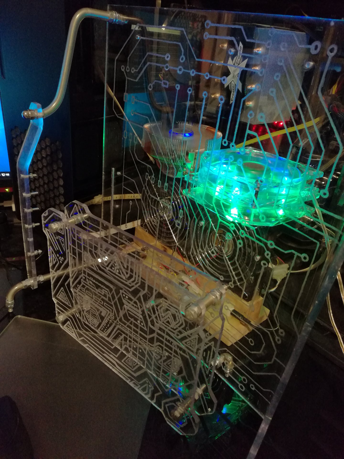
And now some overview pics with the new lights:
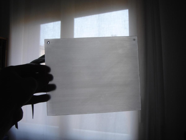
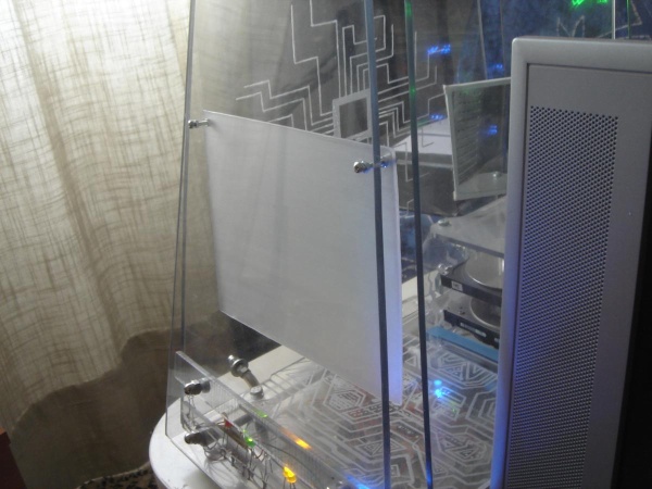
After few months, I replaced the ugly plastic bag that I used as a projection panel, with a polycarbonate 2mm panel that I sanded with sandpaper.
Then I made a sanded polycarbonate cover to hide the feedback LEDs:
I added a thing to the case that I wanted to do from the beginning of the project! 😀
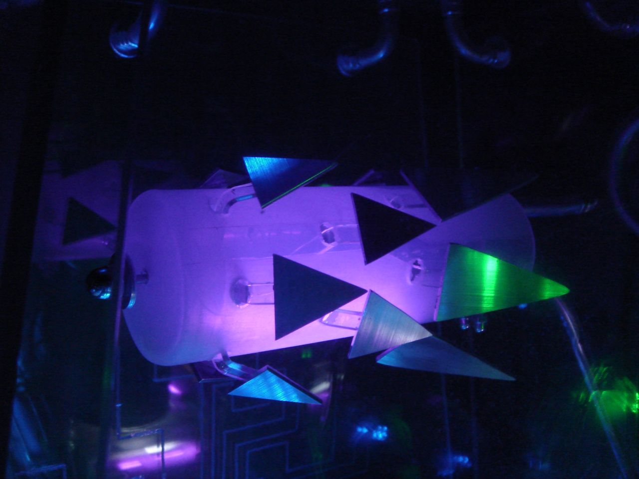
The device I wanted to make was a handmade mechanically moved object, that represented the final weapon of Tron 2.0: the “Prankster Bit”.
This weapon can be seen in this short video, and it is basically a purple glowing cylinder with some animated dark fins flying all around:
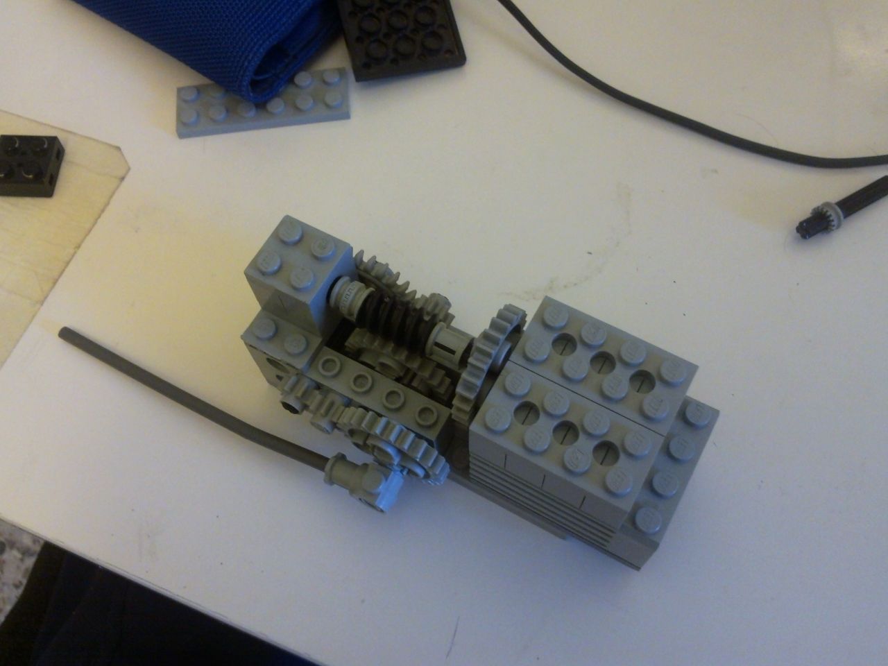
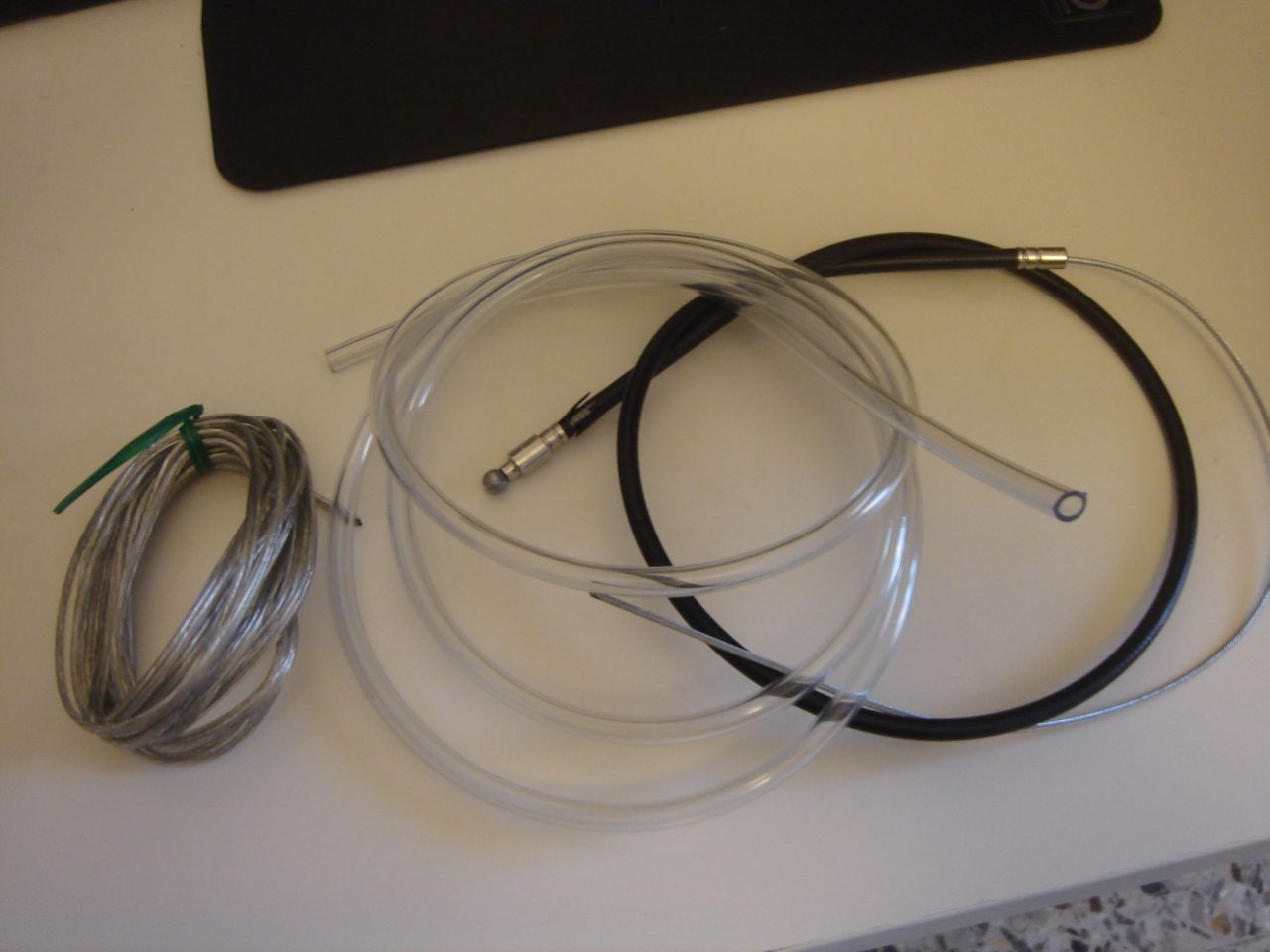
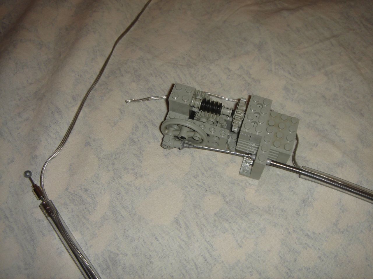
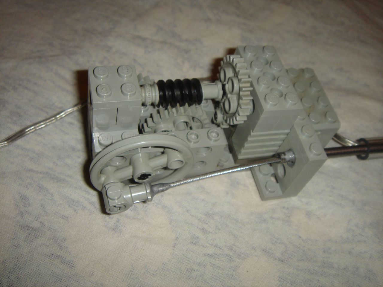
First I needed a slow electric motor to move a bicycle brake cable back and forth: I made it using a motor and some gears from my Lego technic stack:
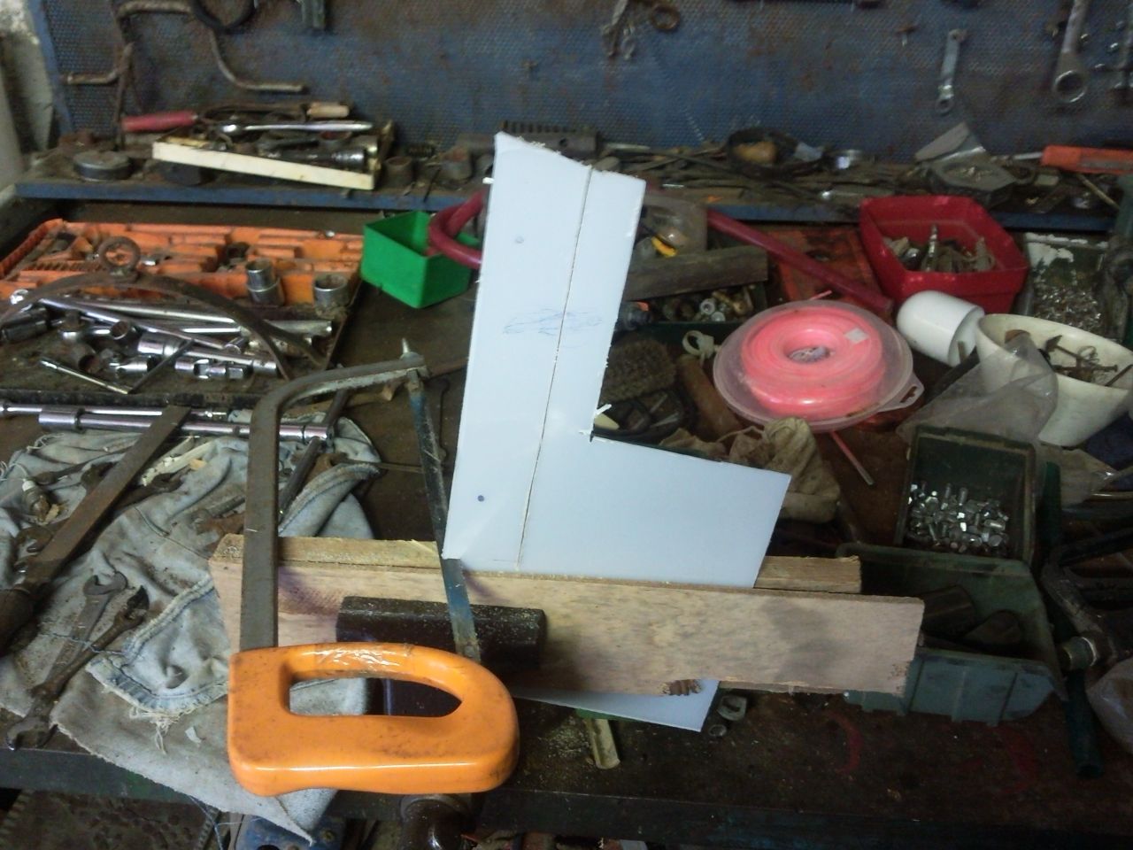
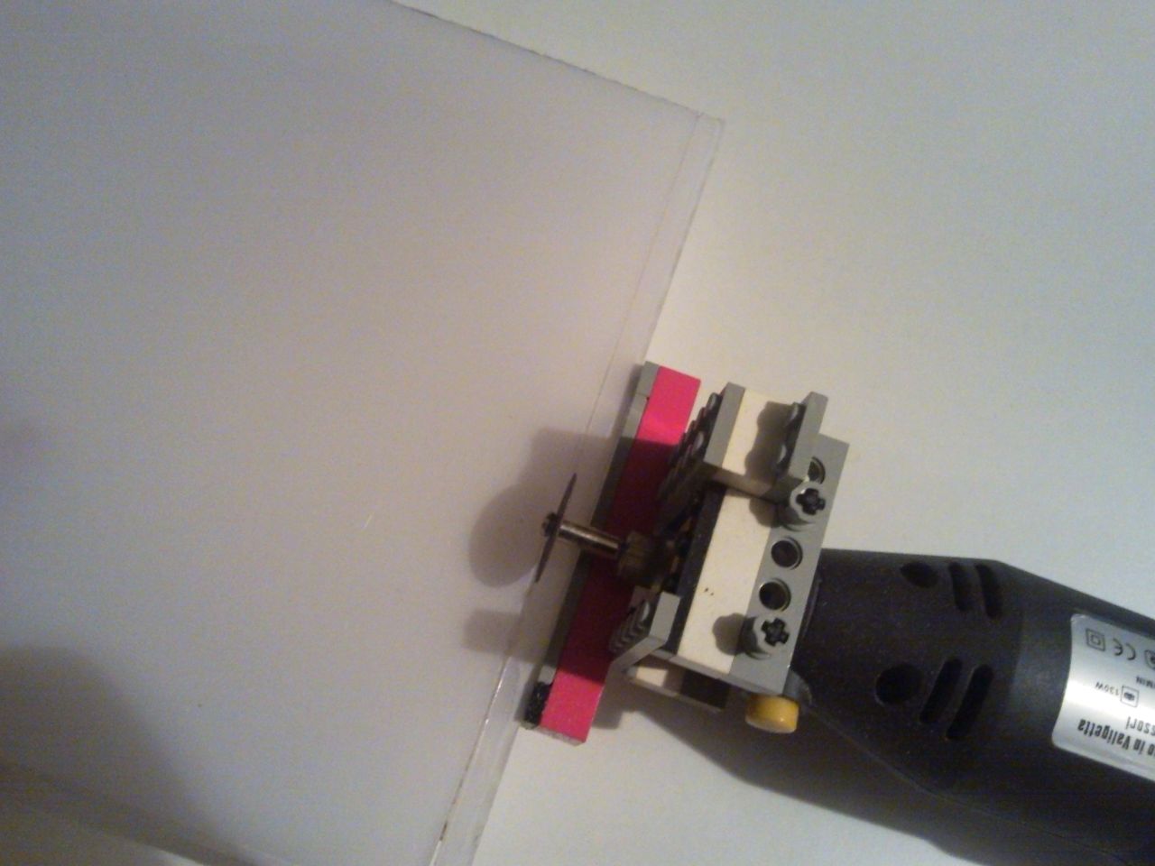
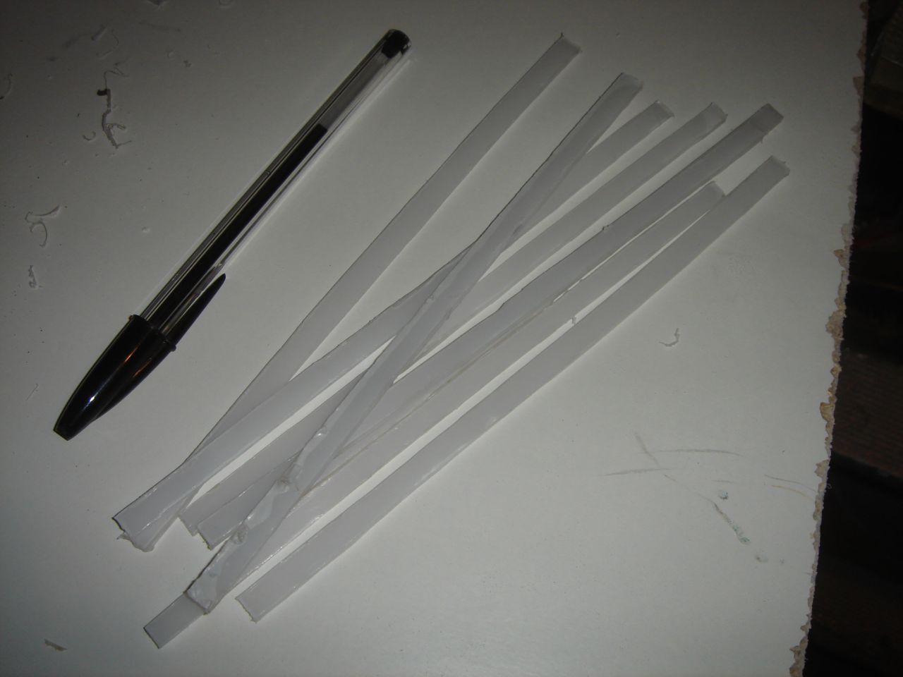
Then I cutted some thin strips of polycarbonate:
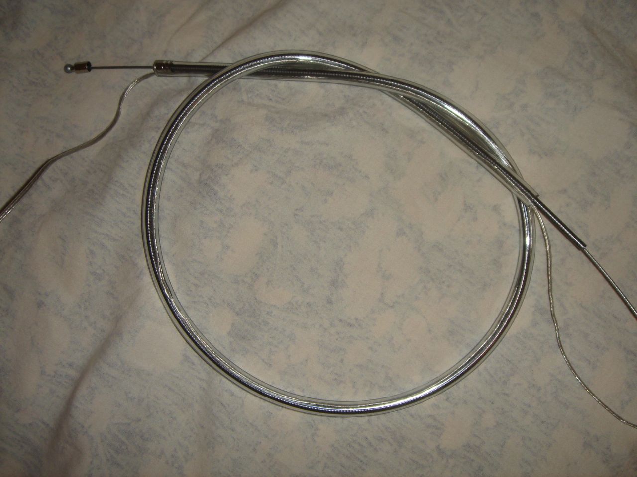
Then I took a bicycle brake cable, I removed the black plastic sheat, and I inserted it with an electric cable in a transparent rubber tube (so the appearance of this cable is similar to the structural joints).
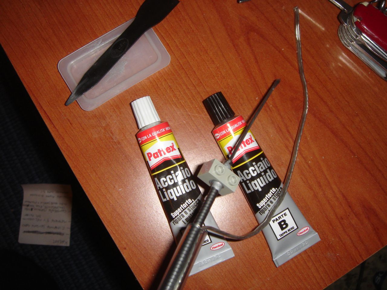
I glued with epoxy one of the brake cable’s ends to two Lego pieces:
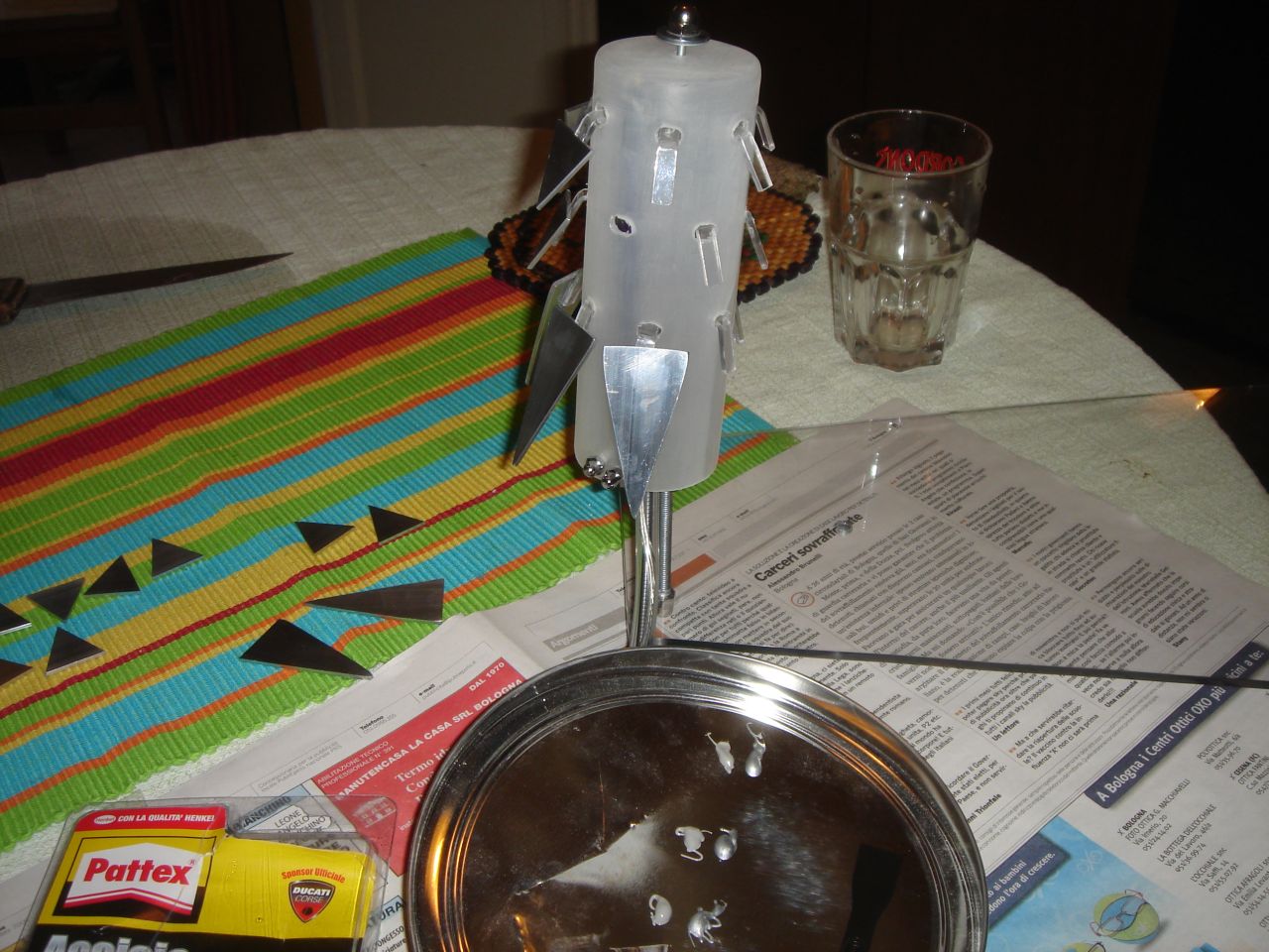
At this point, I started to work on the actual “Prankster bit”:
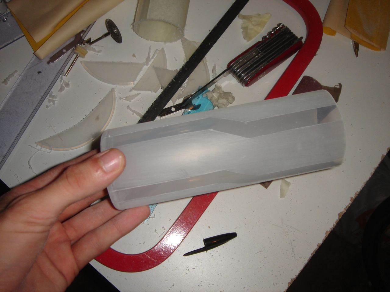
For the glowing cylinder I used this plastic graduated cylinder:
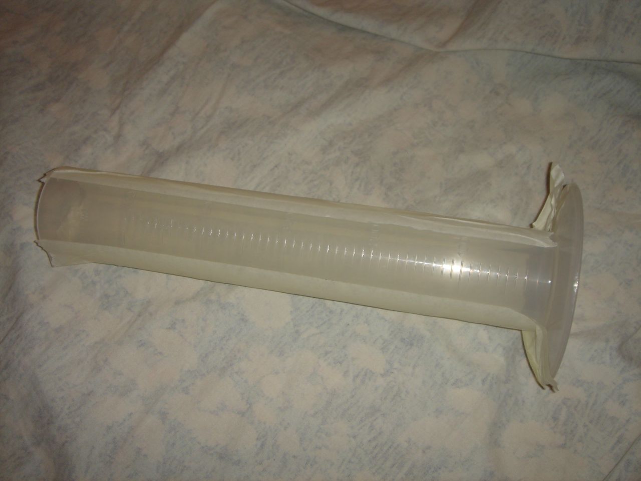
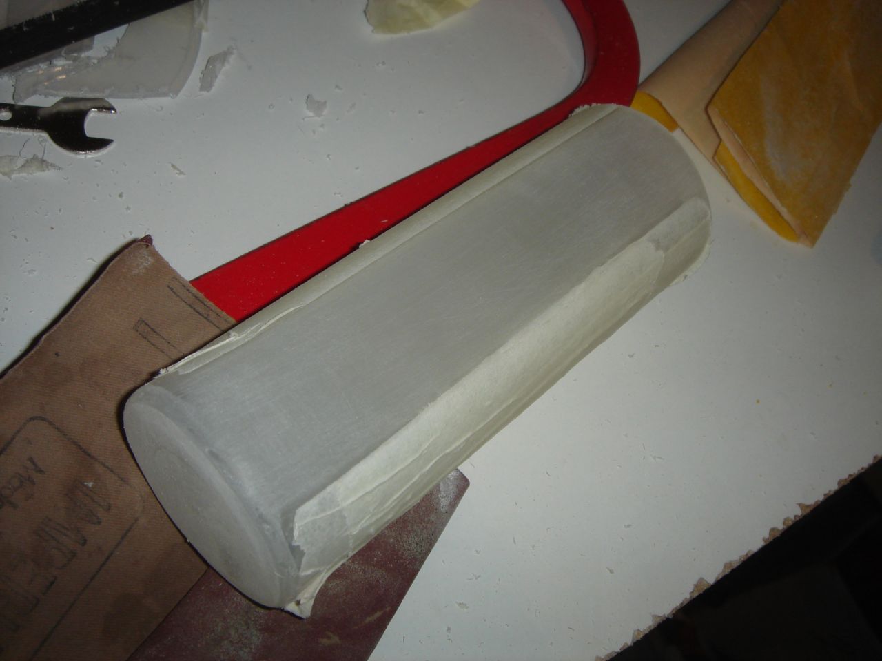
I sanded it to make it translucent, keeping some parts transparent:
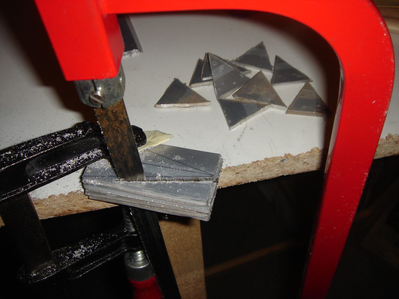
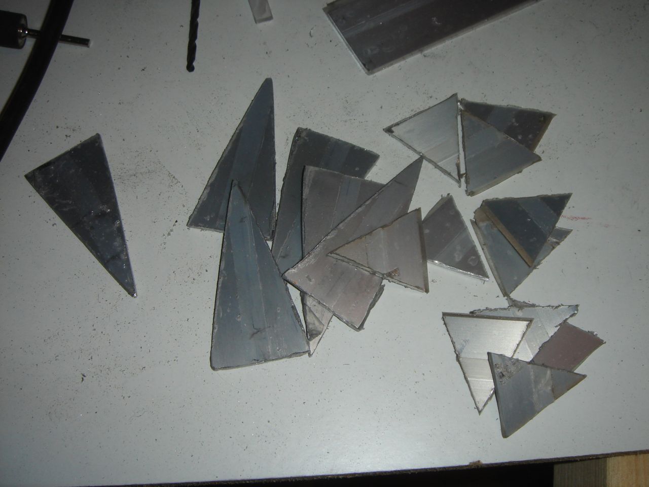
Then I cutted the triangular fins from an aluminium bar:
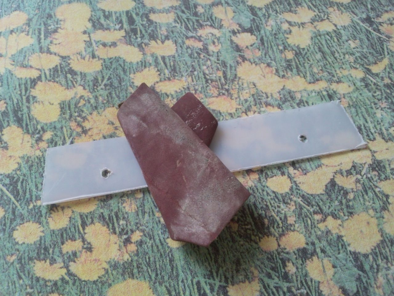
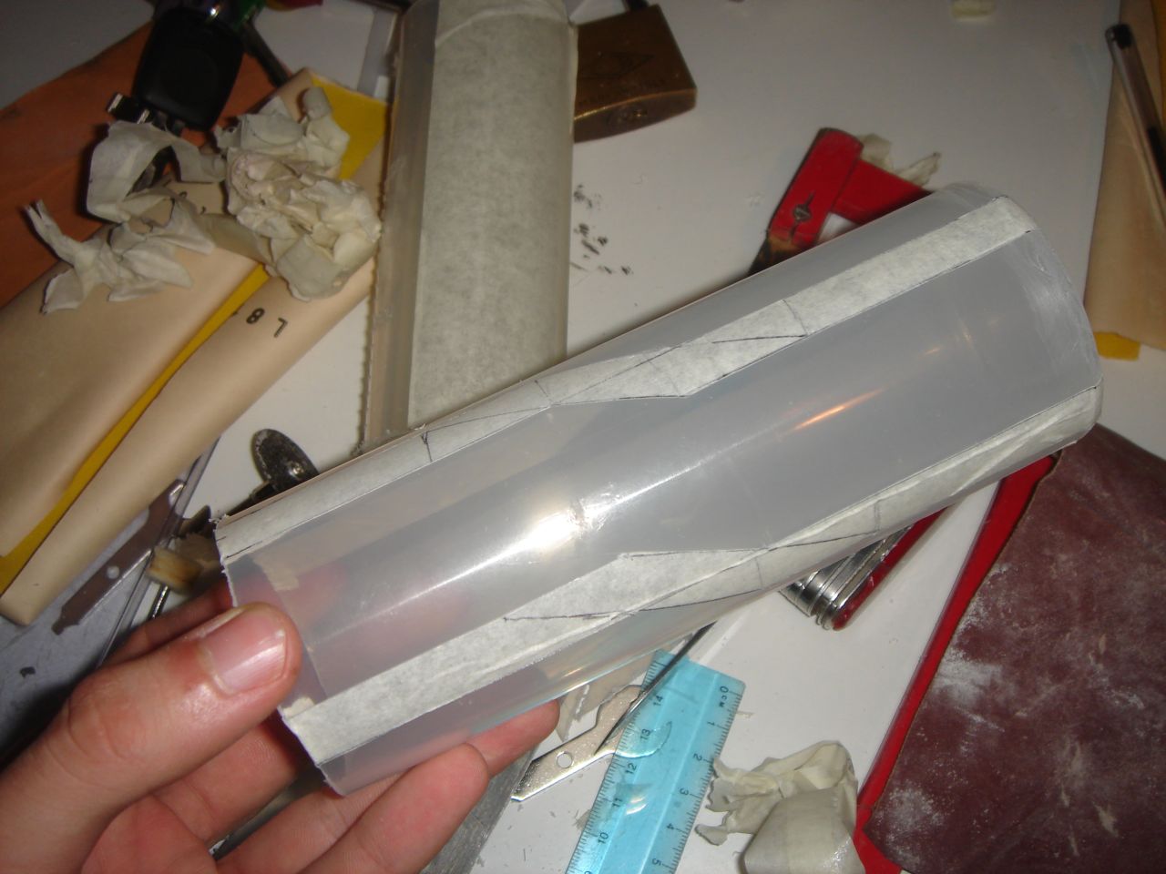
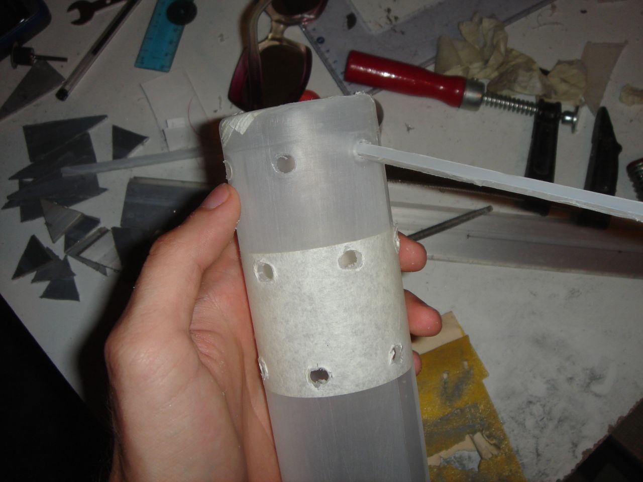
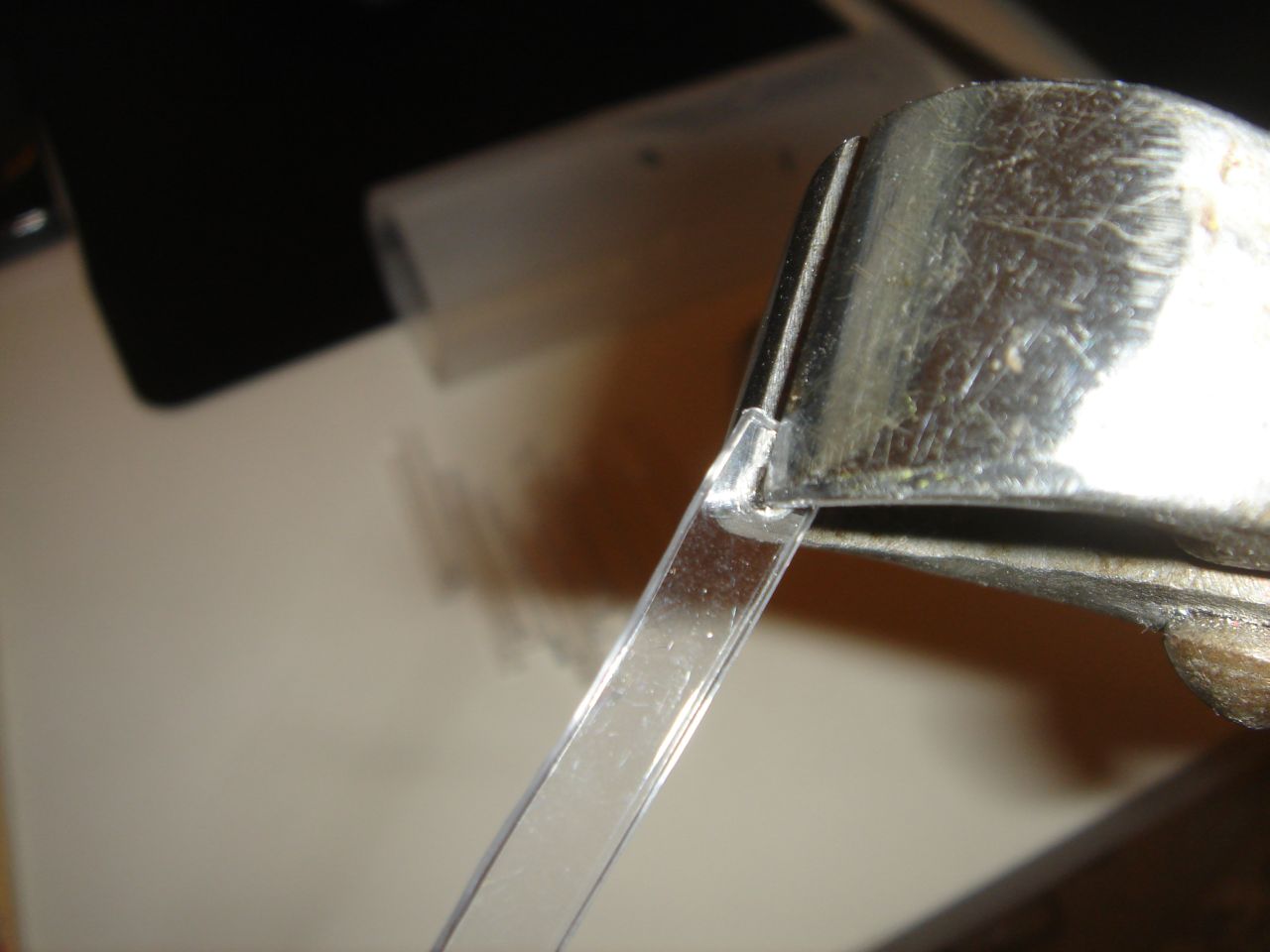
I made some holes all around the cylinder (a hole for each fin), then I polished the edges of the polycarbonate strips:
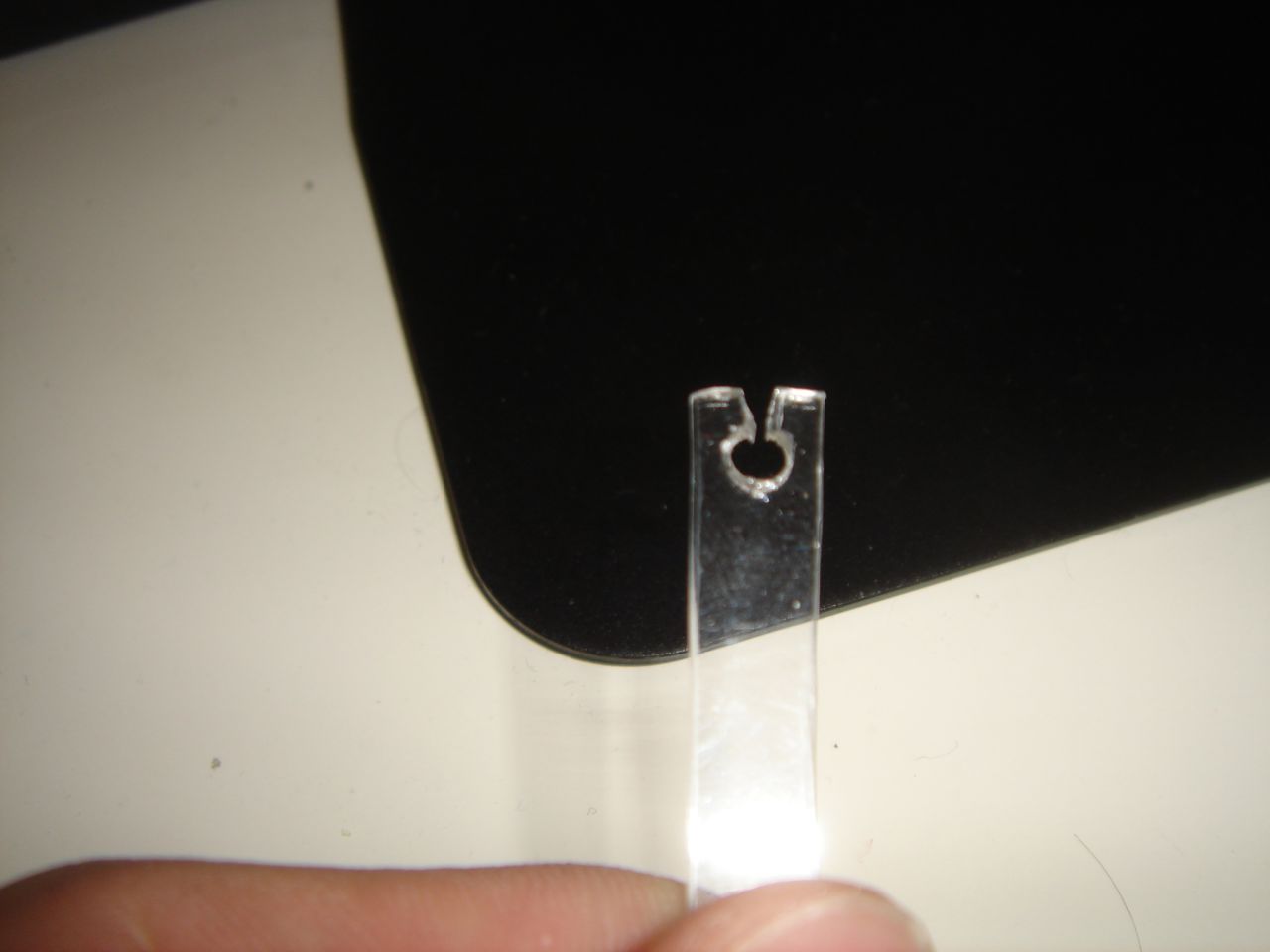
I drilled a hole on the strips ends:
Then I opened this holes, to obtain a sort of socket to join the strips to a central shaft:
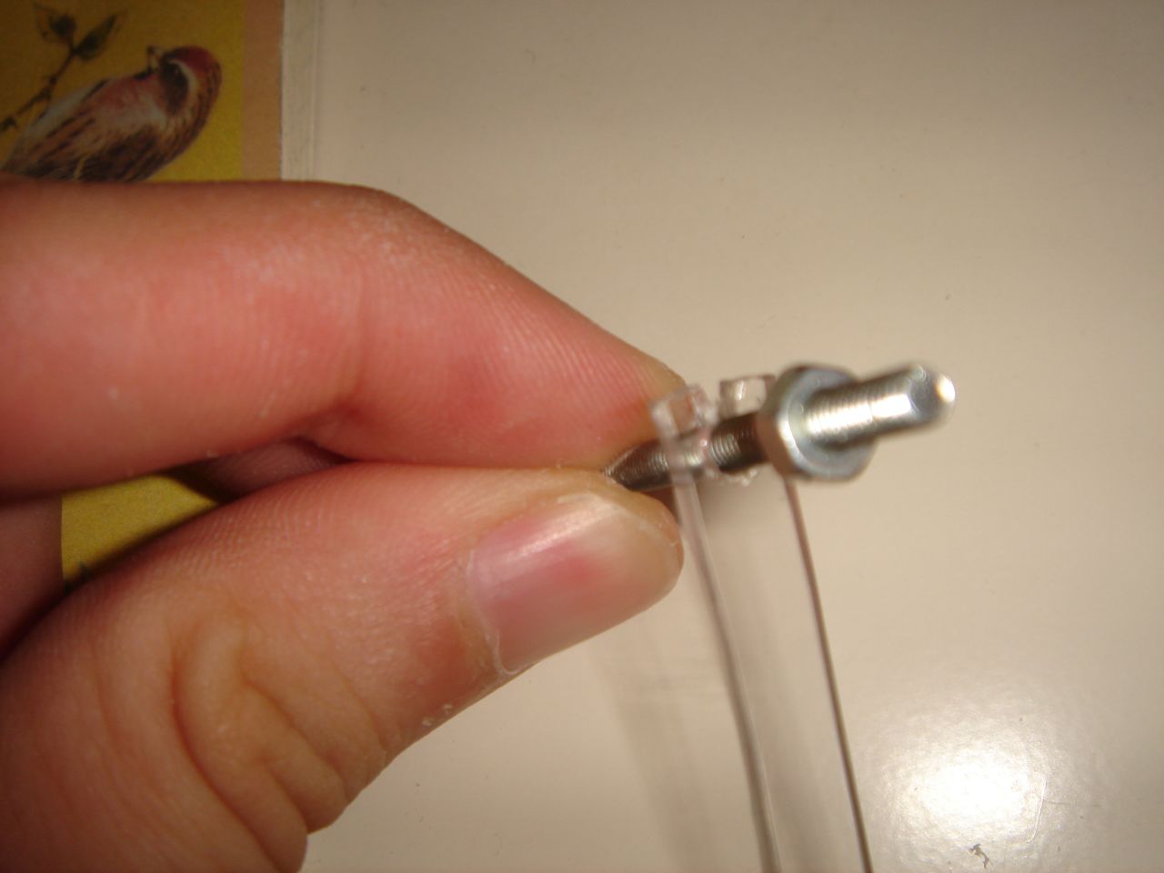
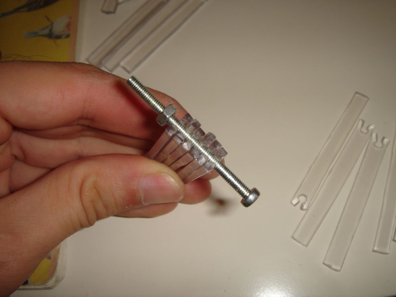
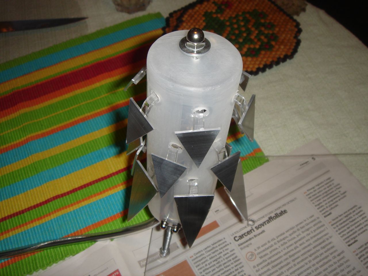
And then I assembled all the strips on the central shaft (a threaded steel bar) in the cylinder:
Now, you can imagine that moving back and forth the central shaft, all the strips will be moved accordingly 😀
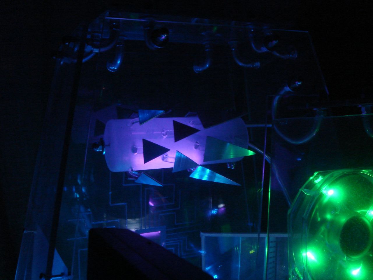
At this point I joined the shaft to the brake cable, and a purple cold cathode light to the electric cable:
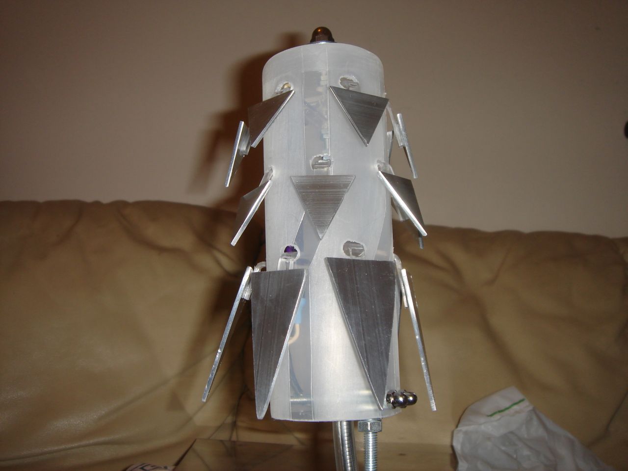
Then I polished and glued the aluminium fins to the polycarbonate strips:
And finally two pics of the assembled and lighted “prankster bit”, mounted in the case 😀 :
10 years after completing the Kernel 1.0, it was unused and covered by dust, but some months ago (in january 2018) I wanted to clean it up and mount my current PC in it.
Initially I wanted to do only this simple upgrade, but after disassembling it I wanted to change and improve many things that I did not like in the old version, so I decided to start the Lonherz Kernel 2.0 project 😀
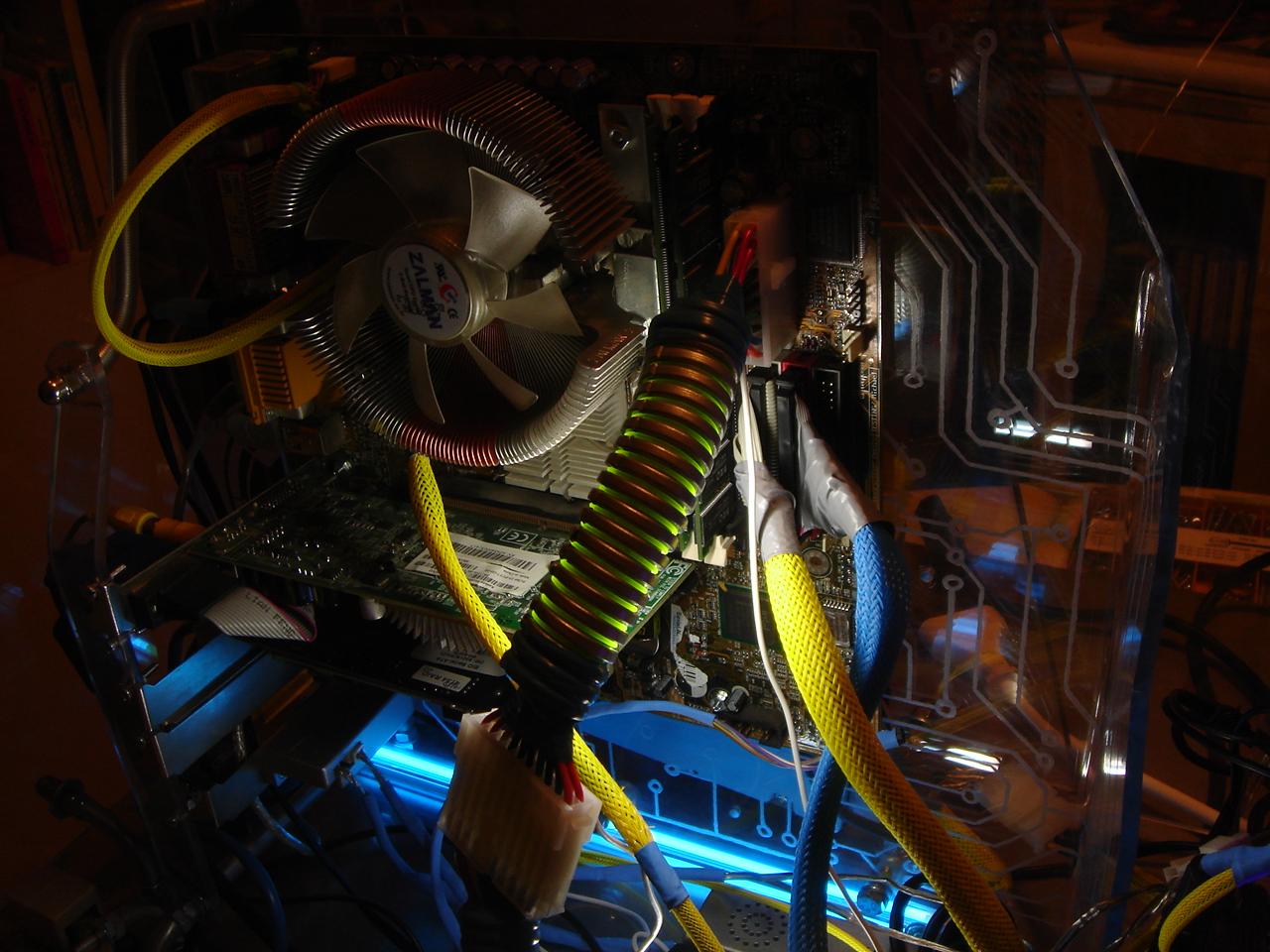
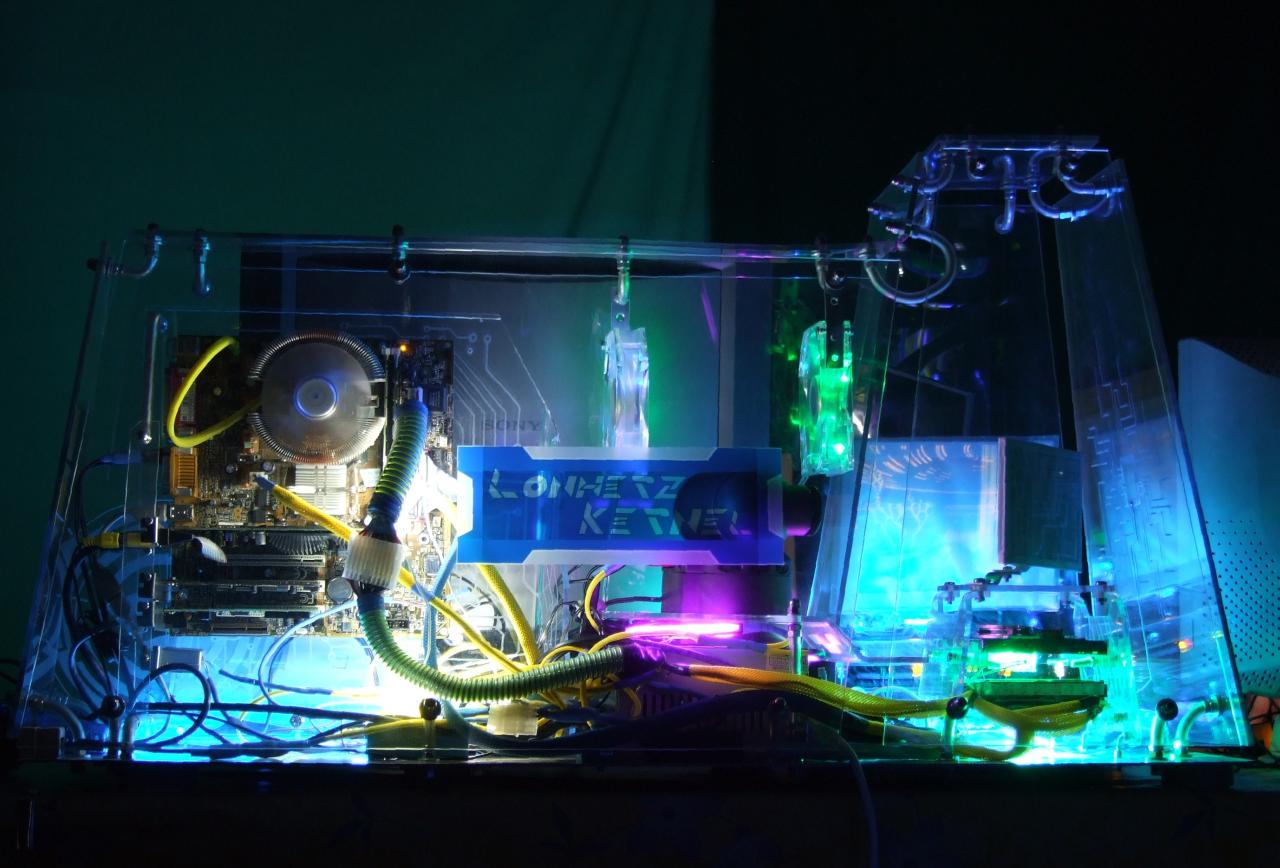
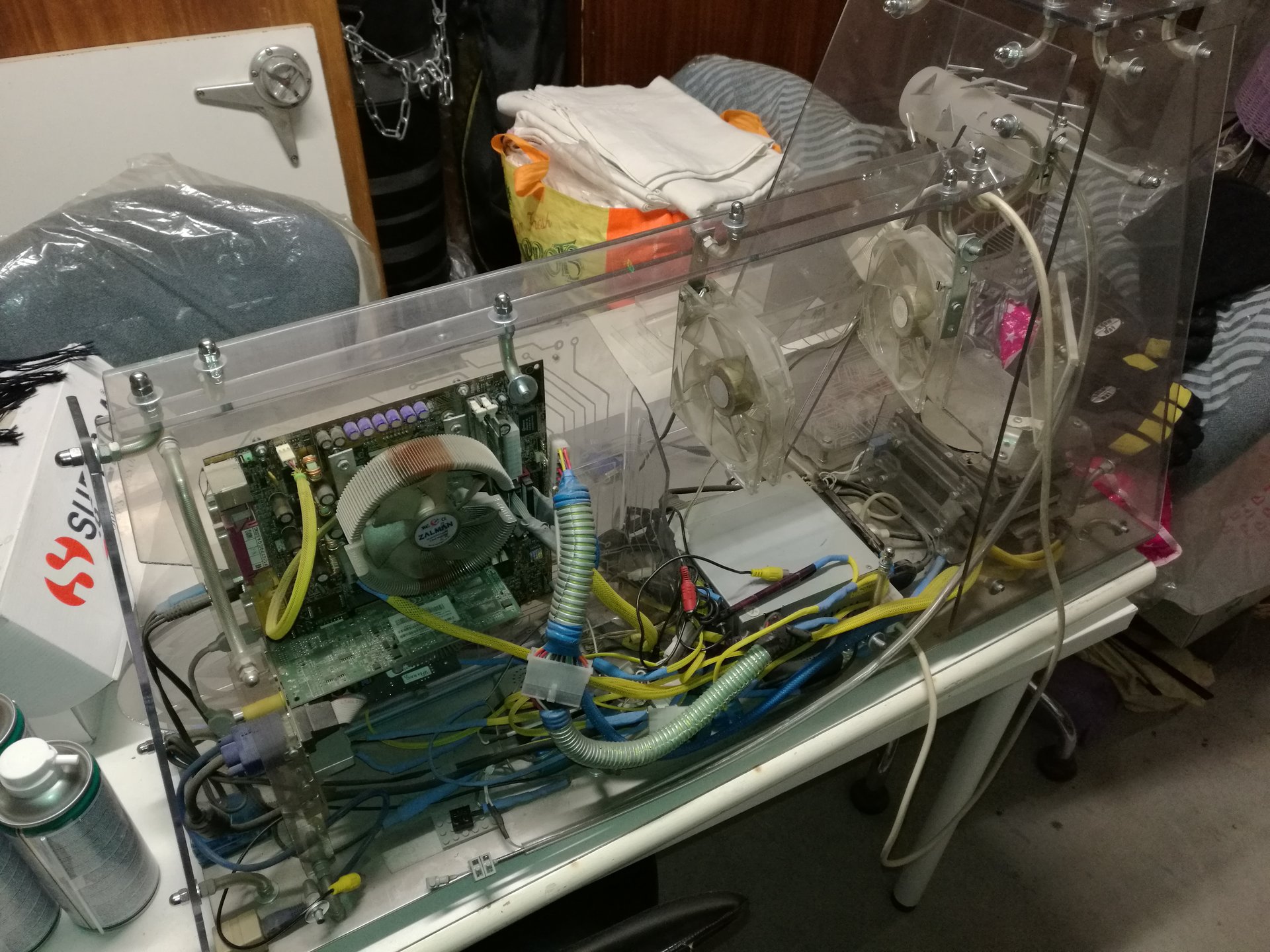
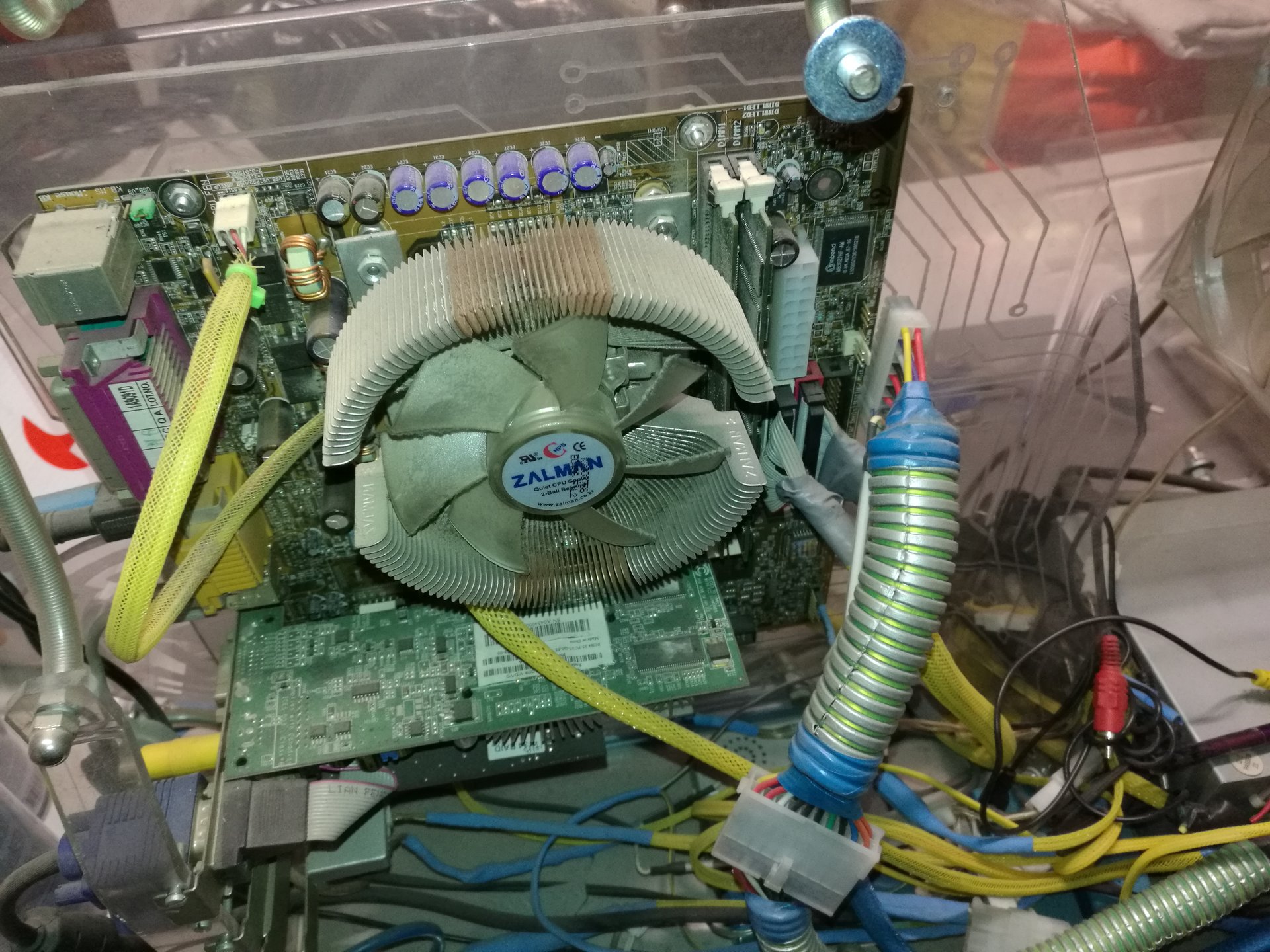
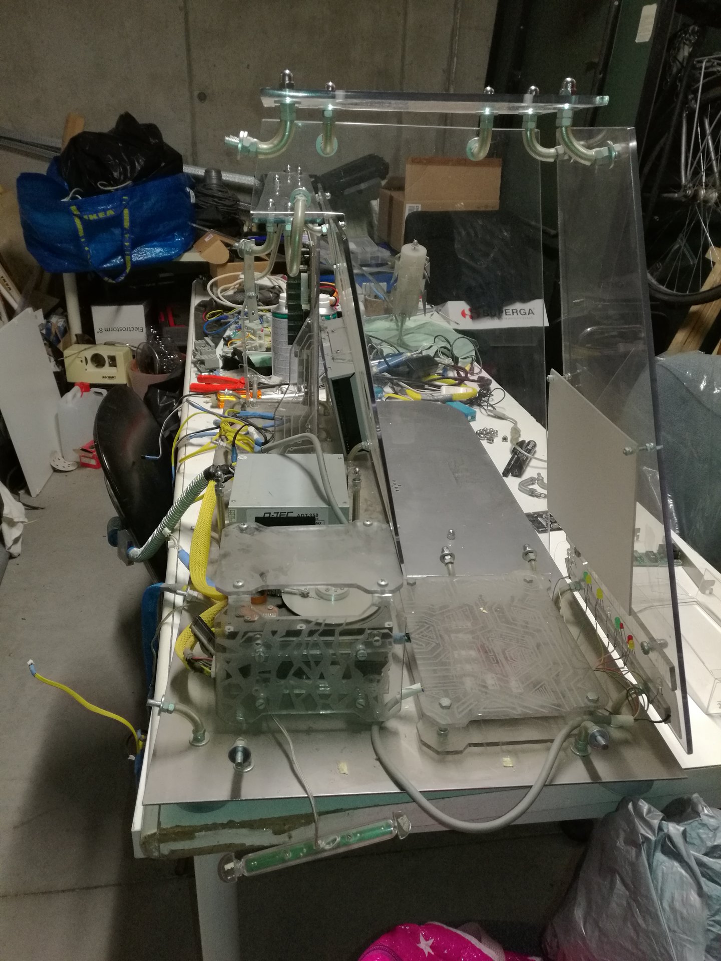
So… 10 years ago we left it like this:
The first job I had to do on the case was disassembling it and cleaning all the parts from a thick layer of dust (I had to wash them!)
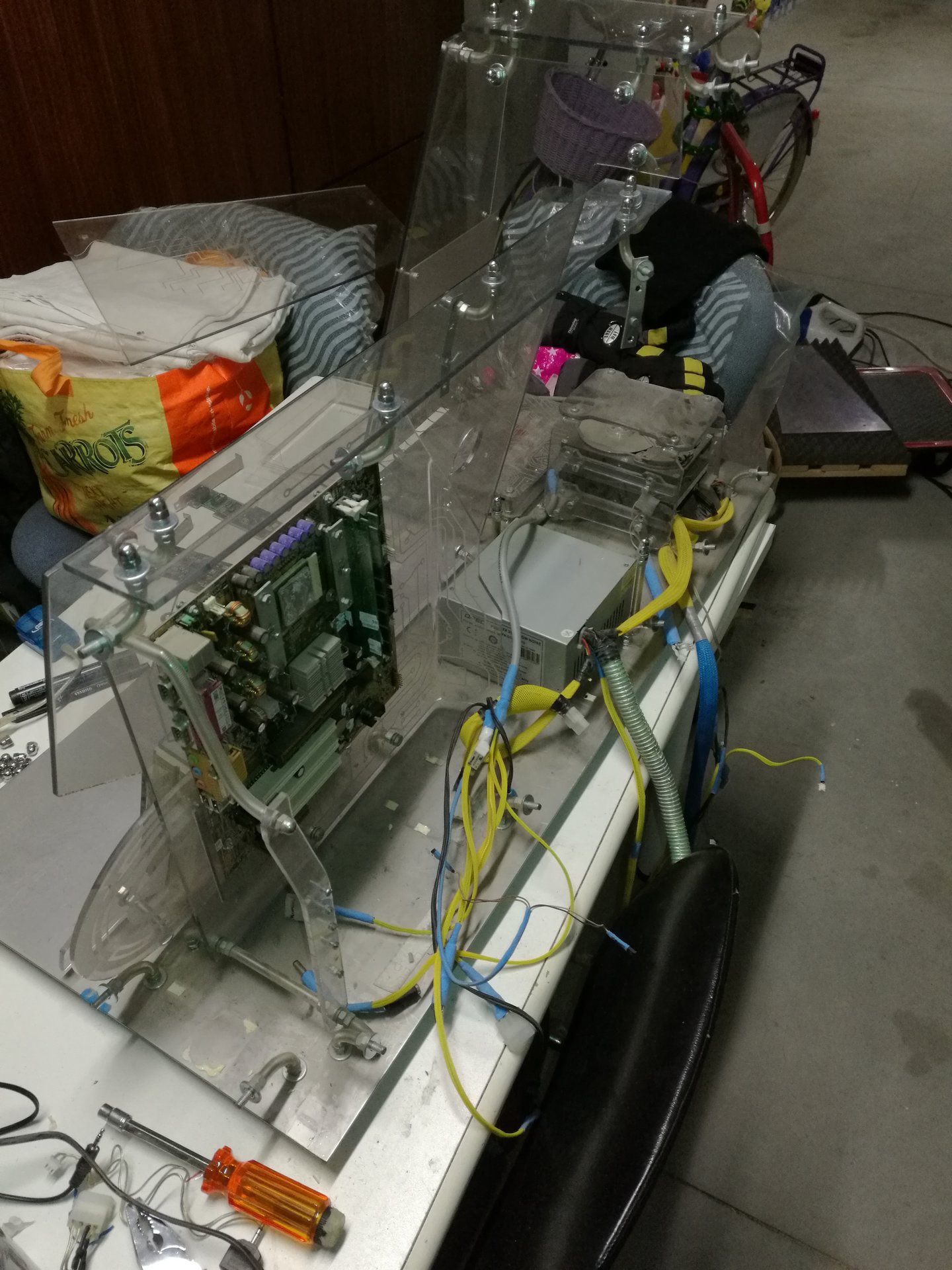
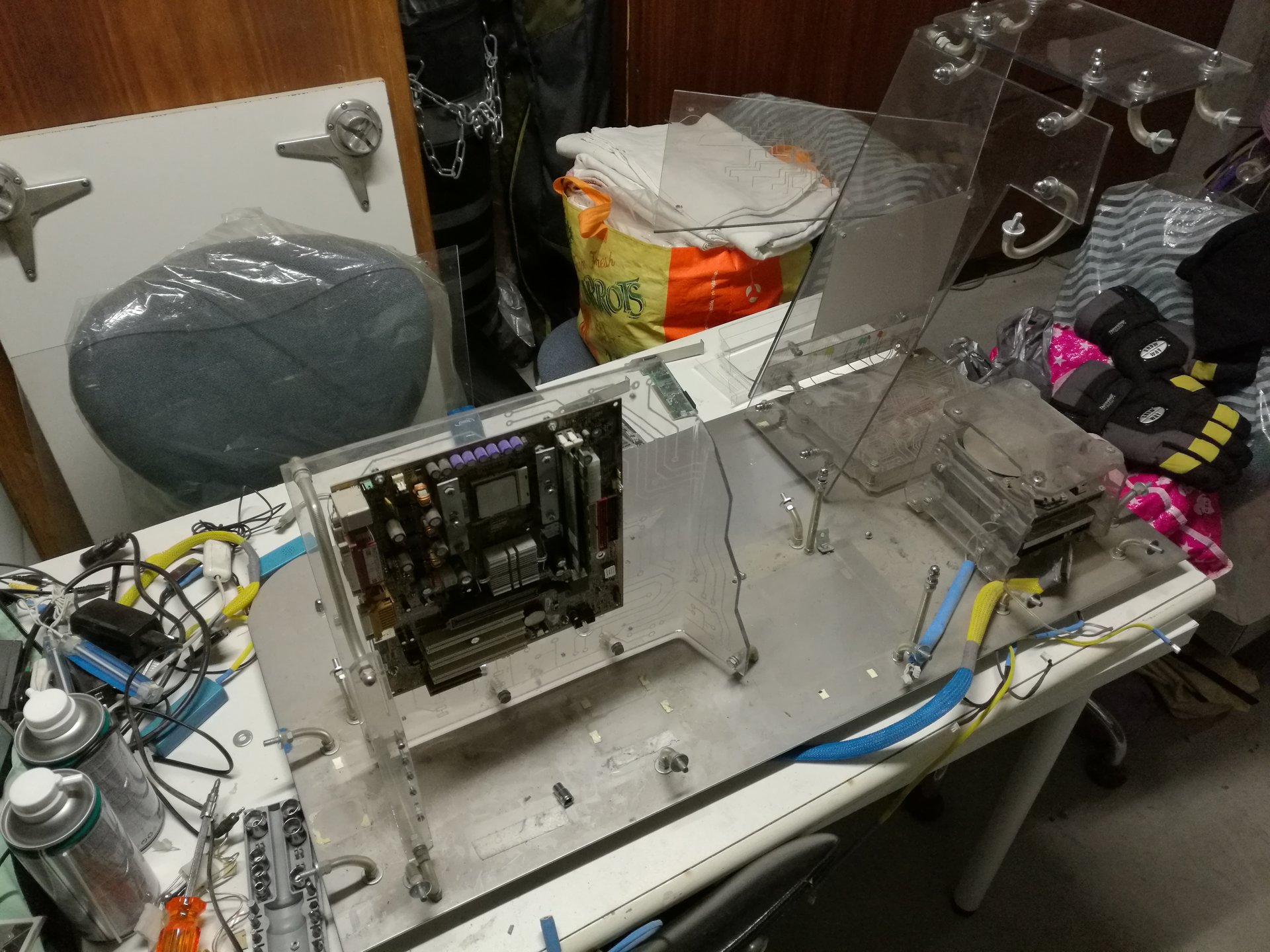
Here I’m disassembling the case (this was the first time I had dissassembled it!):

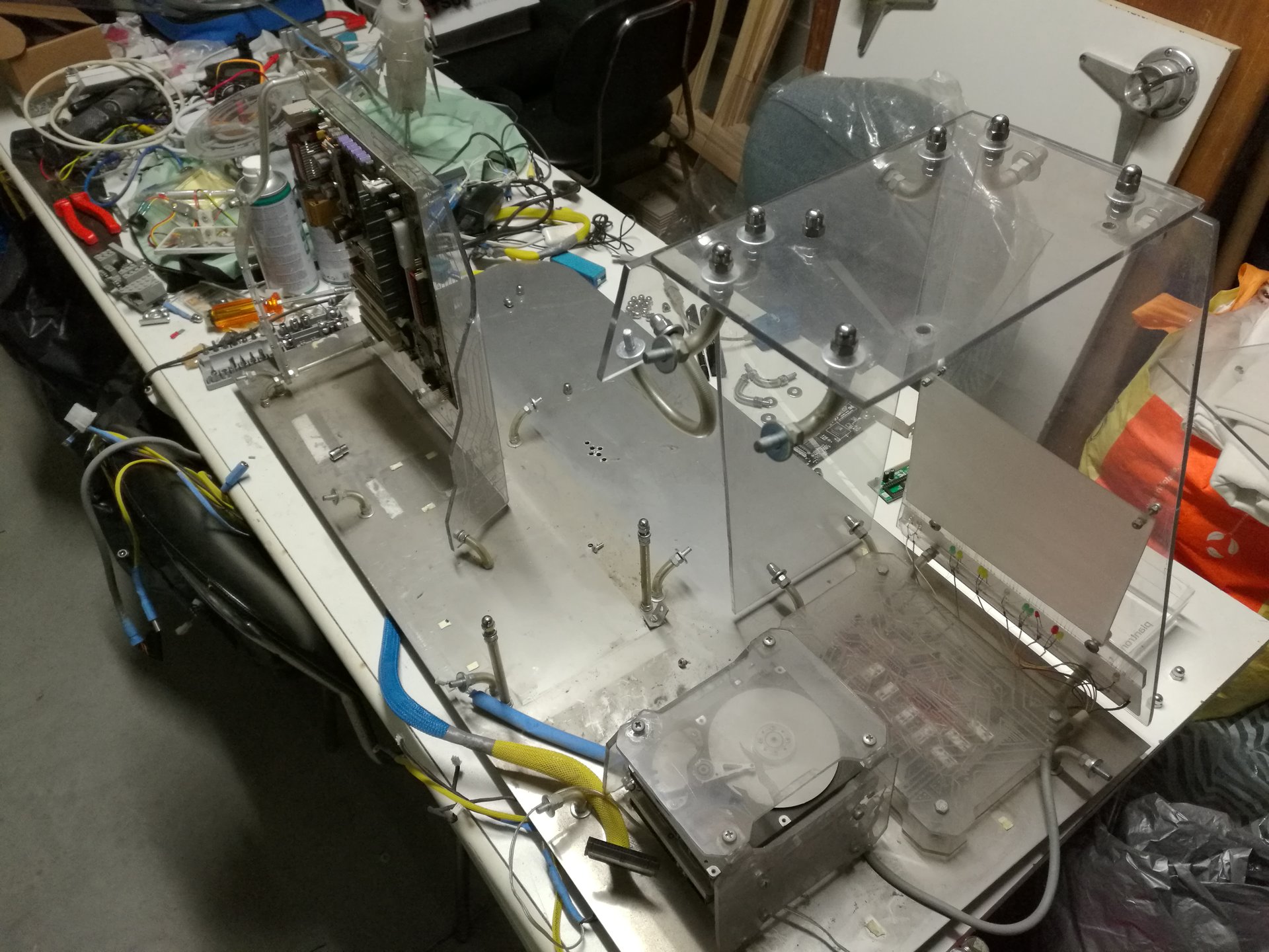
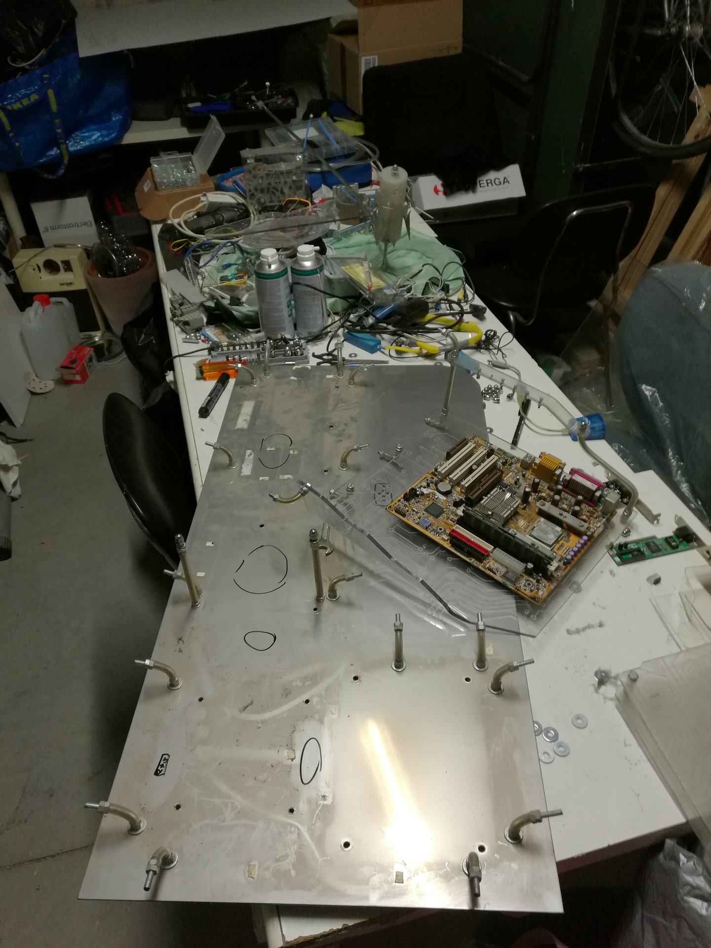
and here I have washed the inner structures:

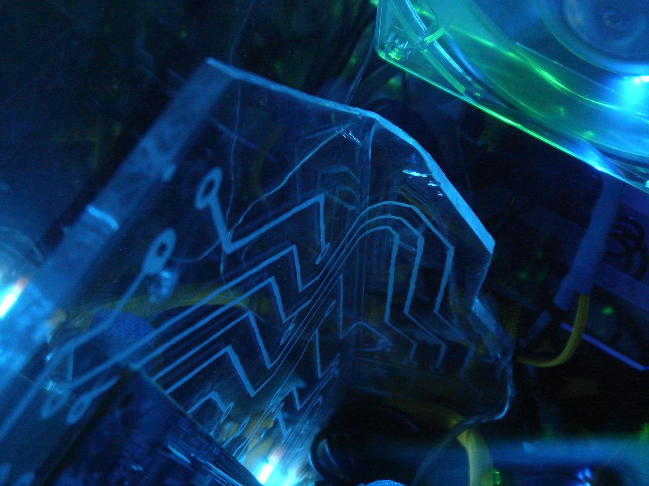
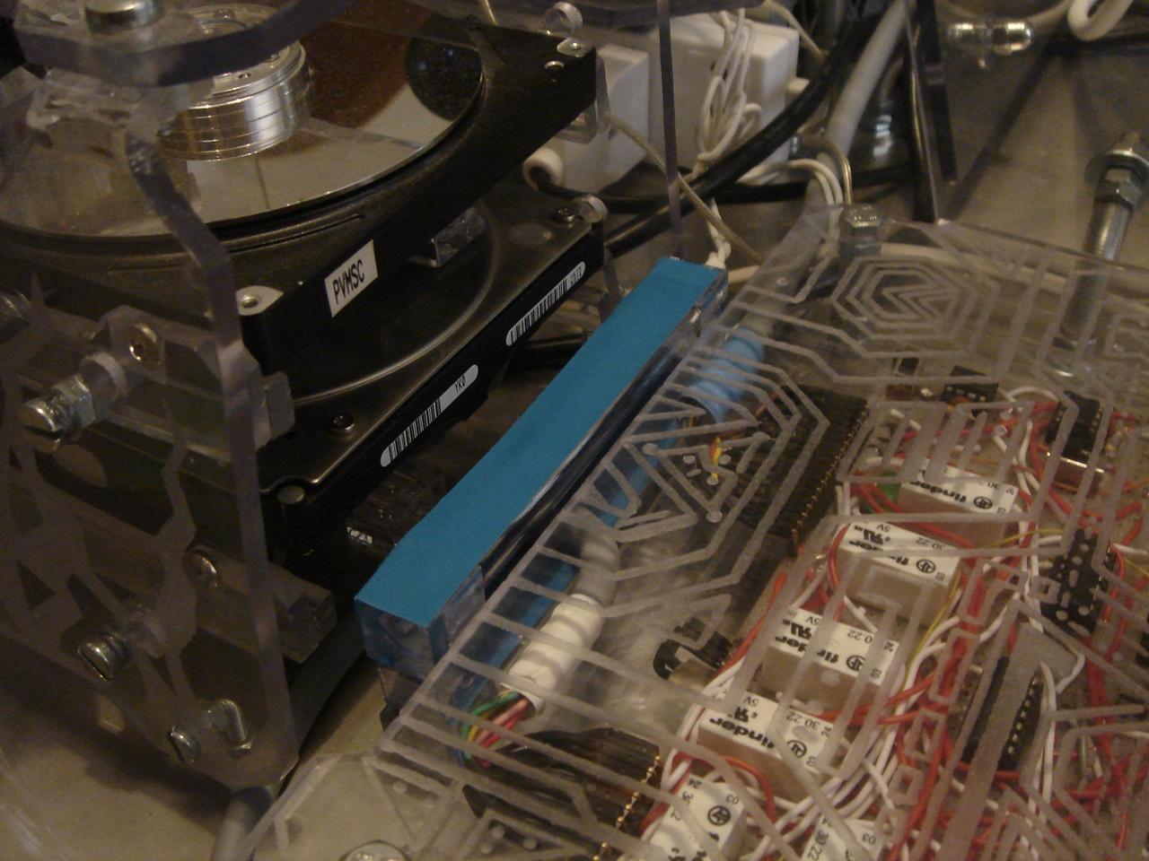
There were a lot of things that I wanted to improve, but in the last pic of the Kernel 1.0 we can see immediately one big flaw: there are a lot of engravings, but they are badly lighted (in particular the one behind the motherboard).
This is due to the use of cold cathode tubes, that spread light at 360°.
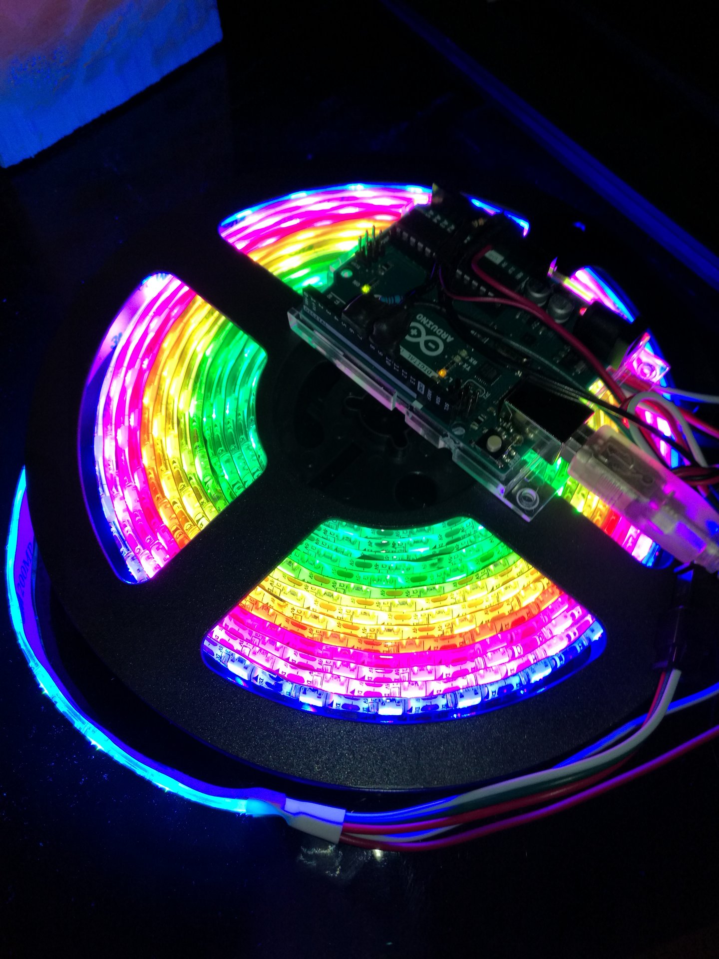
To “shot” a concentrated beam of light in the panels, I thought that some RGB LED strips attached on the bottom of each engraved panel were a lot better for that purpose.
The LED strips also have two other advantages:
– the colors are much more vibrant and intense compared to the colored light produced by a cold cathode tube
– I have chosen the addressable LED strips, so I can set individually the color of any single led of the strip
In particular, the addressable led strips give me absolute freedom to set any kind of lighting configuration for the case: monochromatic light for the whole case, one color for each component (like the original setup of 1.0), transition effects, etc.
Furthermore, using an Arduino board to control the strips, I have programmed custom animated lighting effects for some components (for example, the infected sector can gradually go from a clean blue to an infected pulsing green color, showing the ongoing infection).
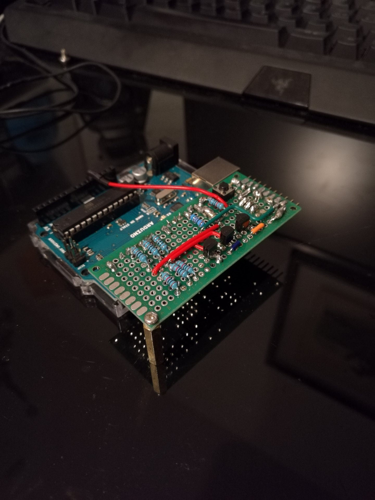
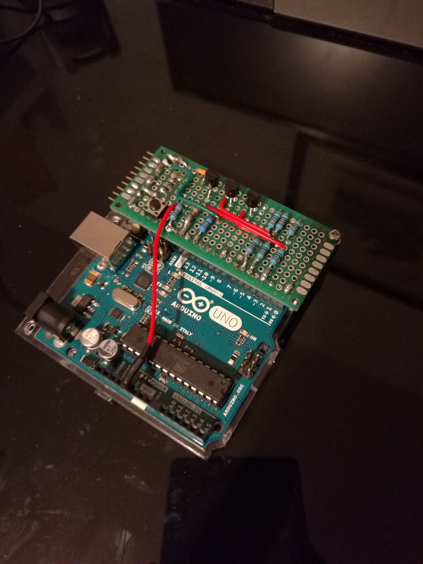
The first thing to do was to make a custom circuit to be connected to Arduino.
This circuit implements:
– the link between Arduino and the addressable led strip
– a standard 3 channel RGB led strip controller (this is to control the RGB CPU heatsink)
– the link between Arduino, the proximity sensor and 2 touch sensors
– the link to the power supply
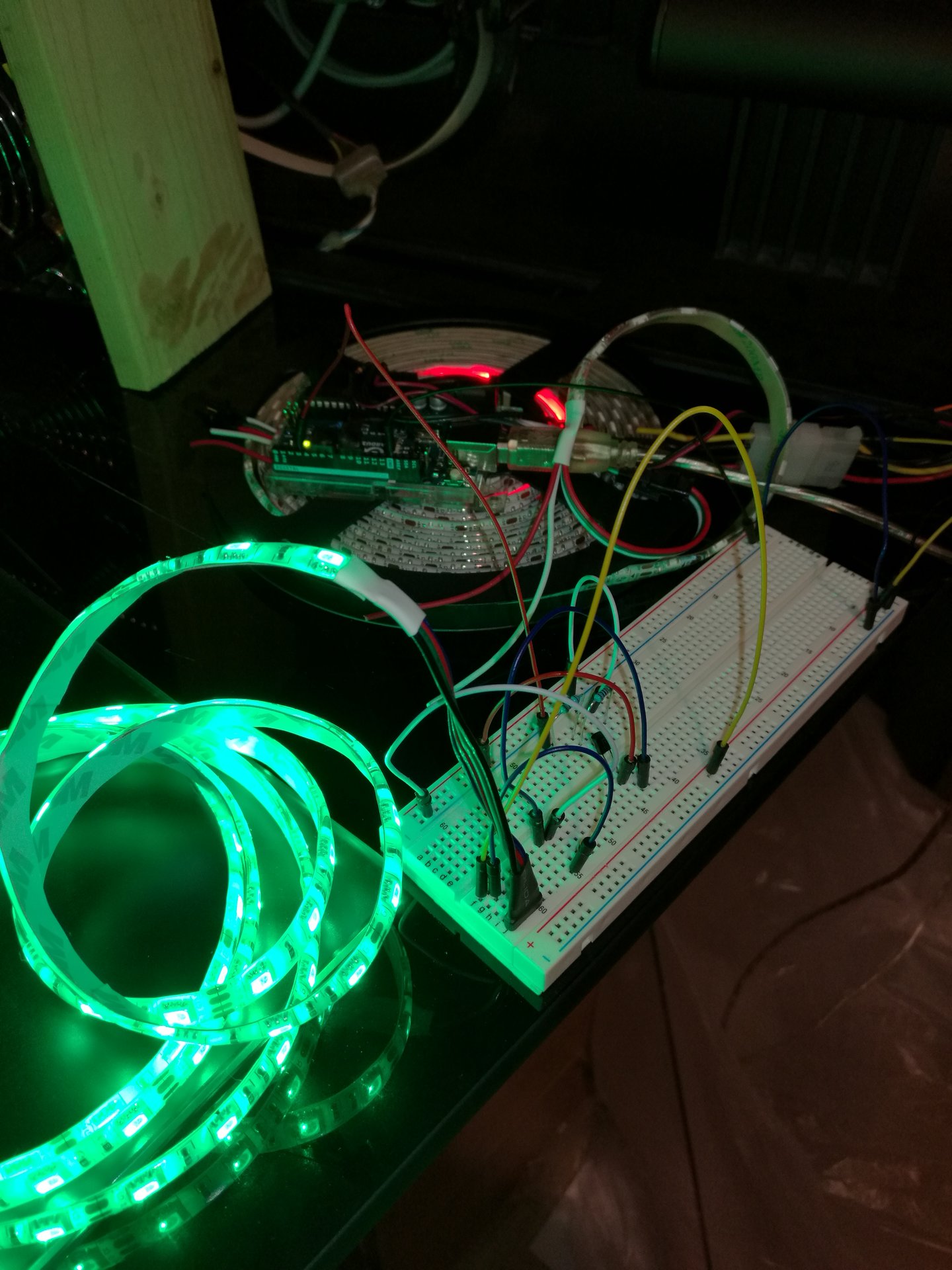
This is one animated effect of the led strip that I have programmed in Arduino:
And this is a video of the same effect:
I first try the circuit on a breadboard:
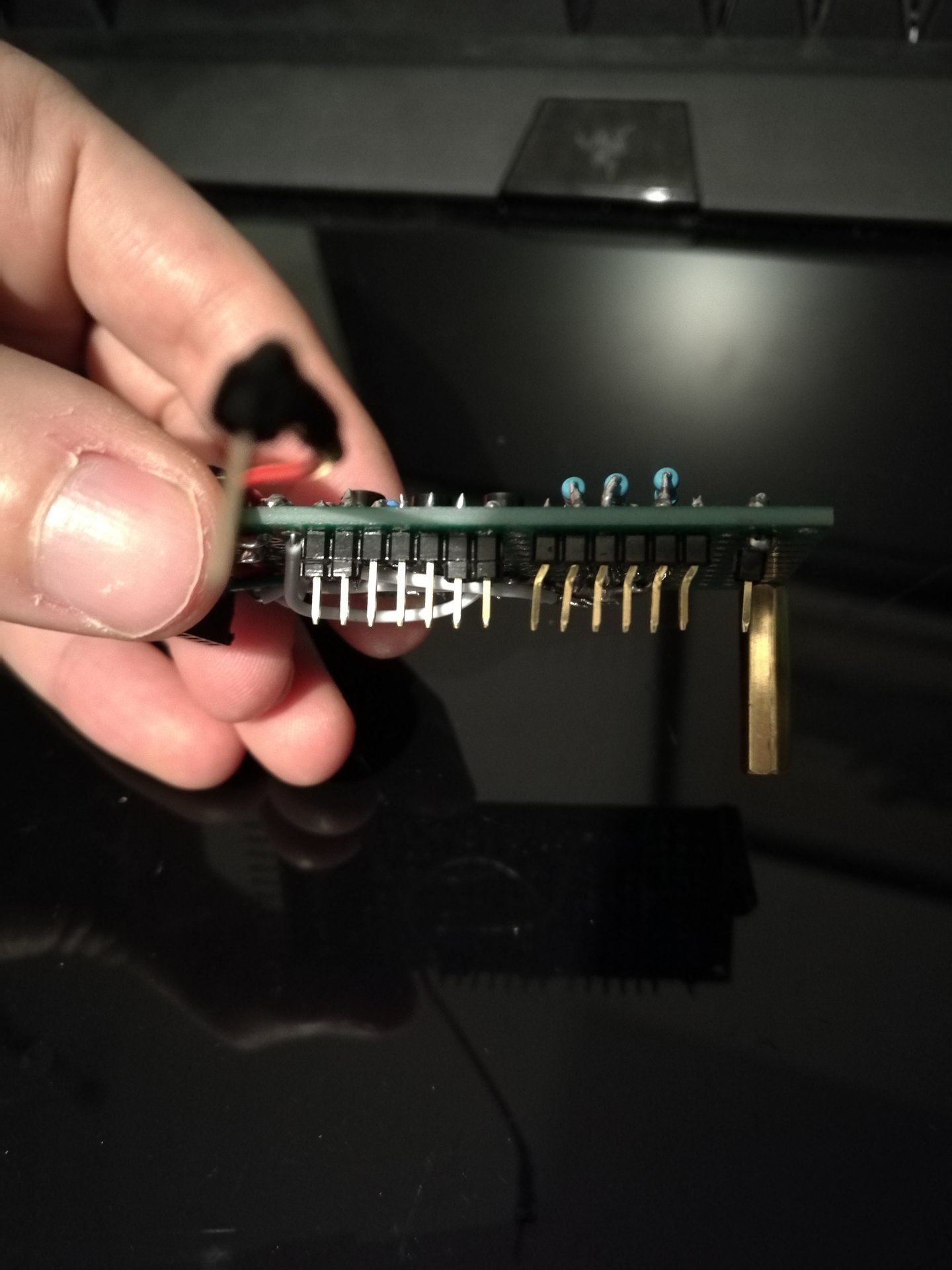
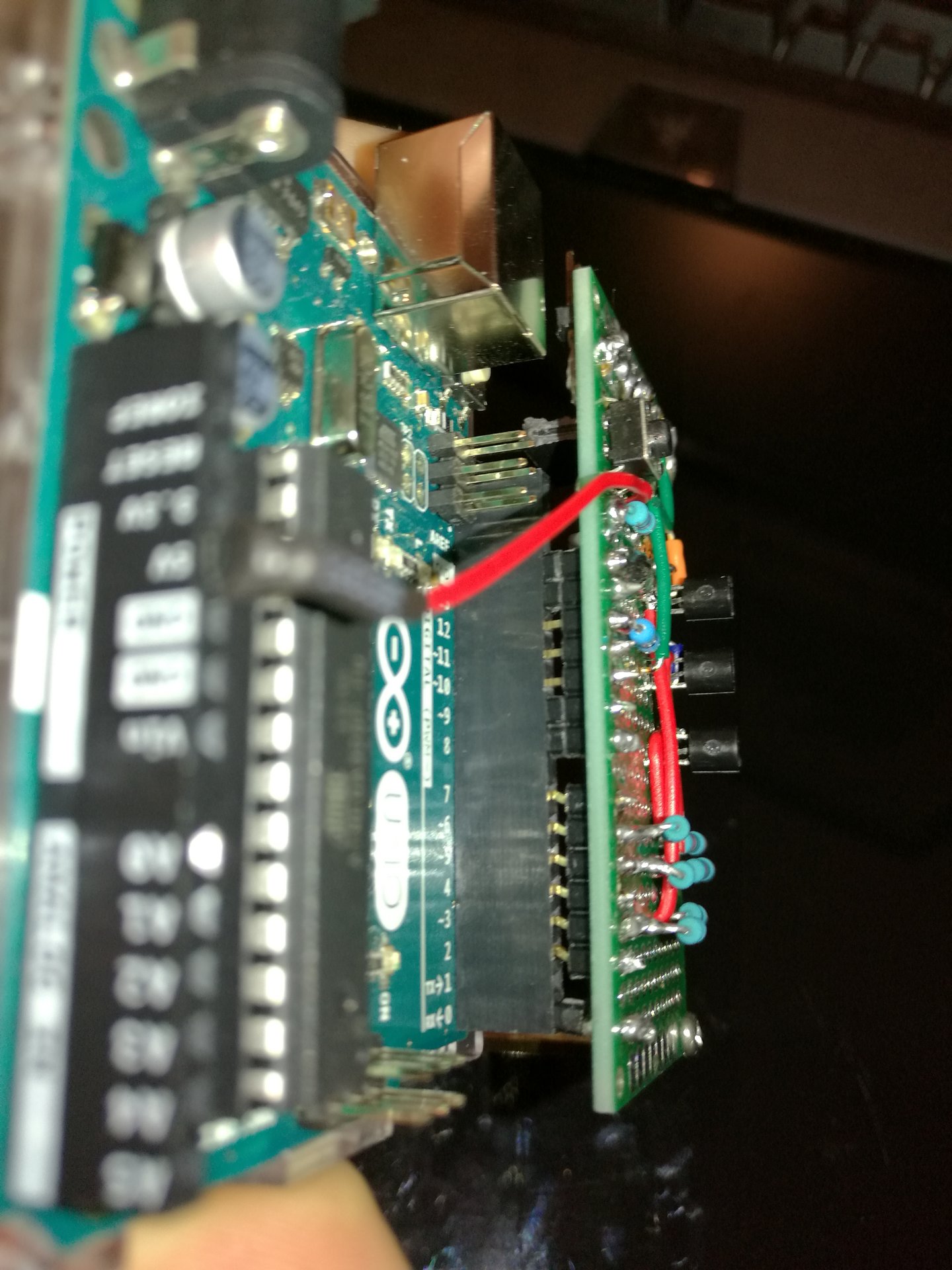
Then I make the actual circuit:
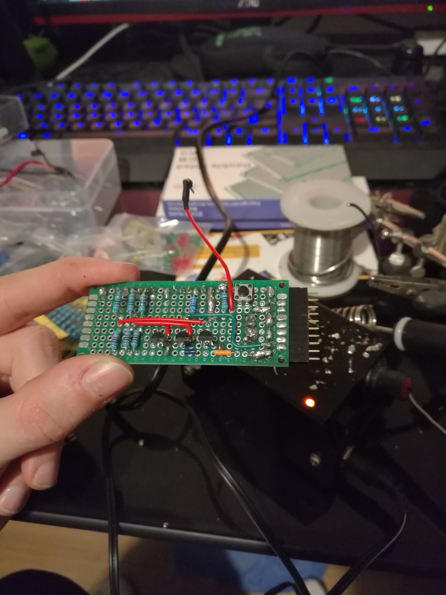
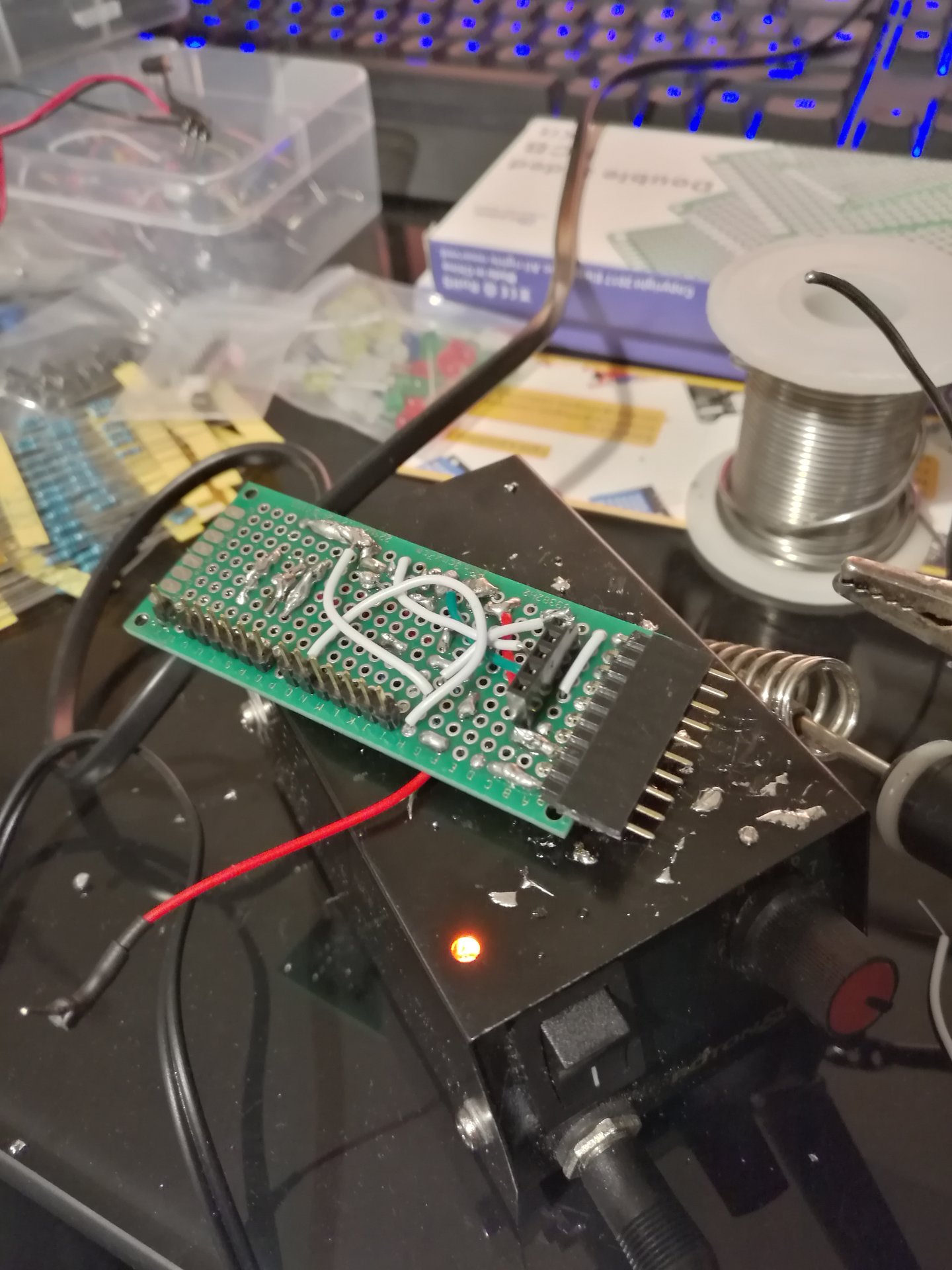
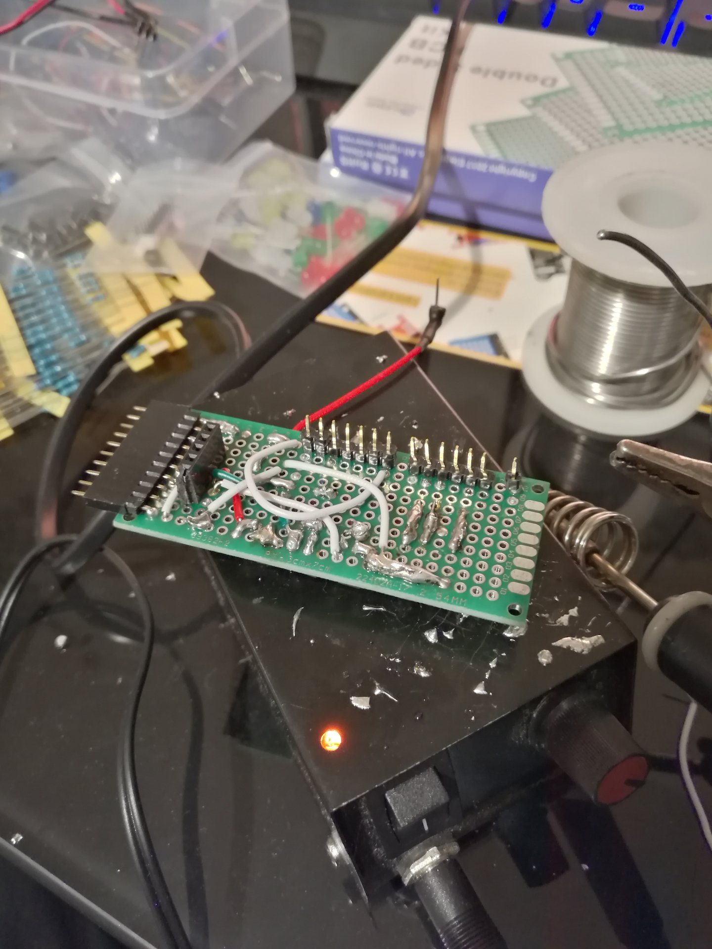
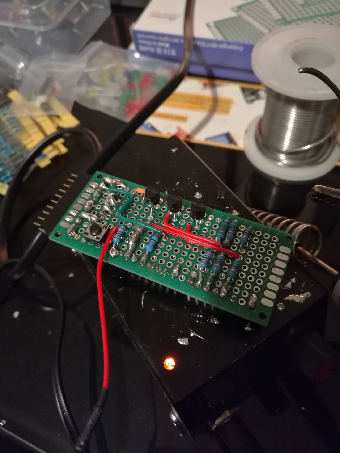
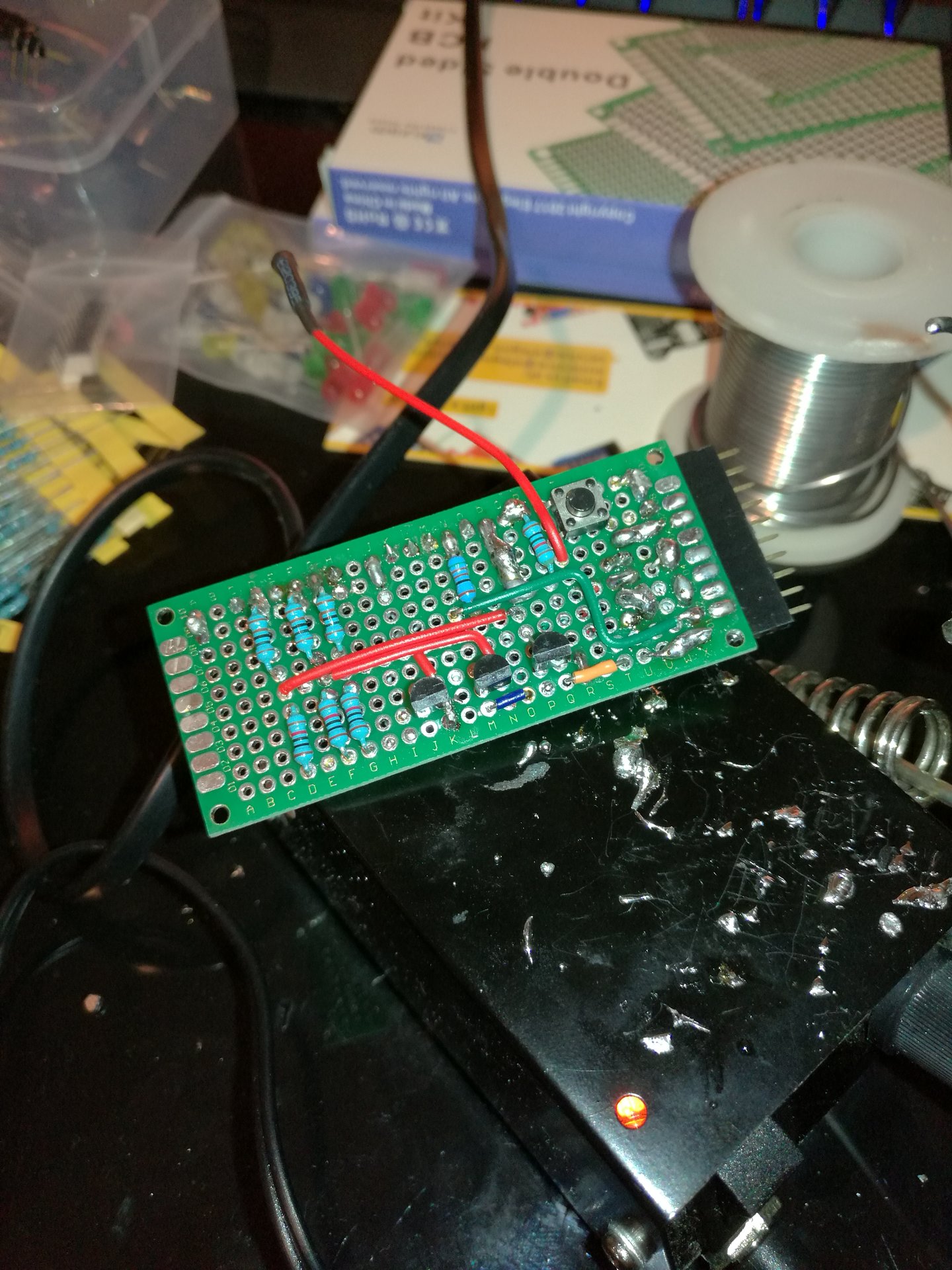
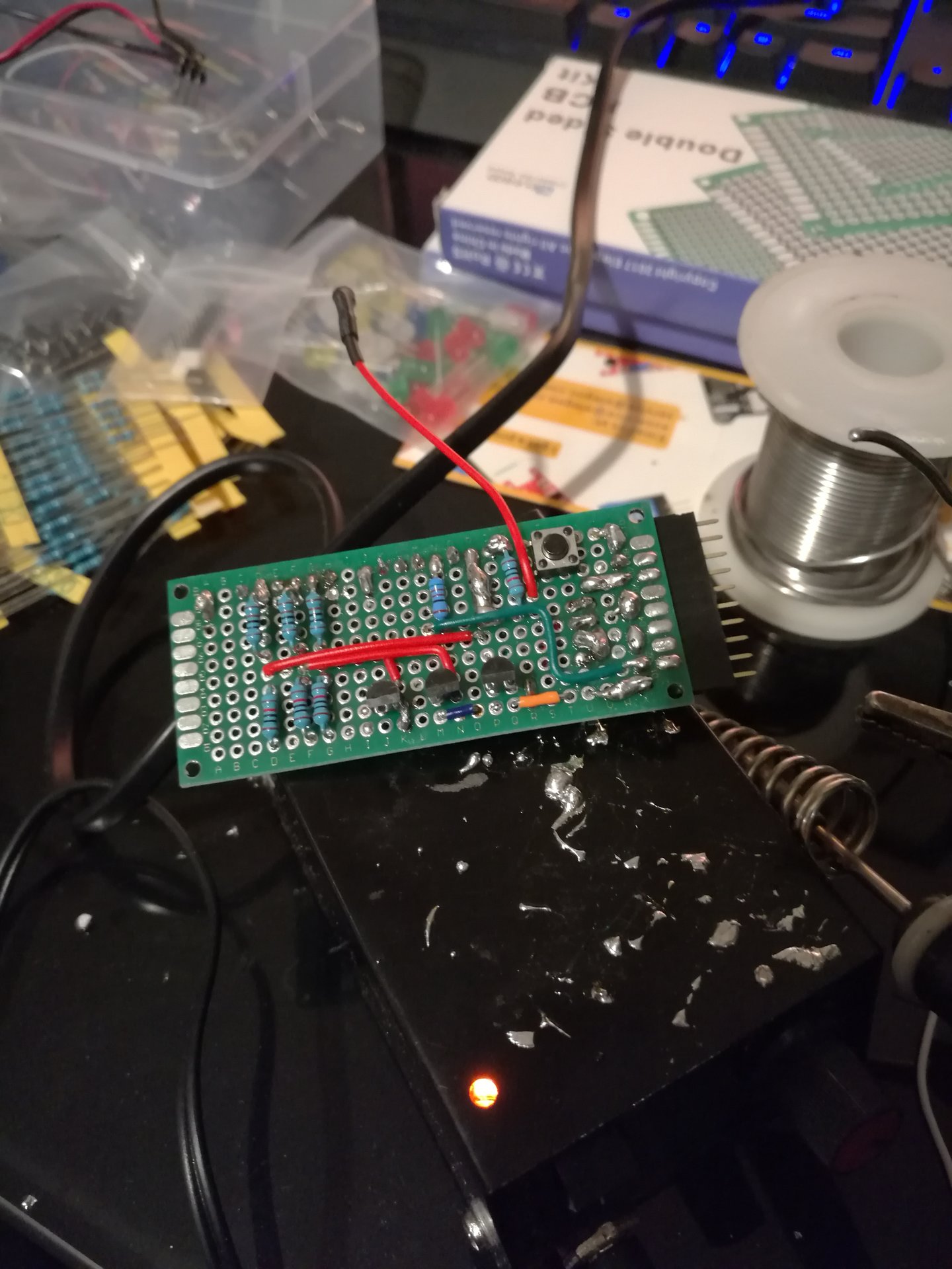

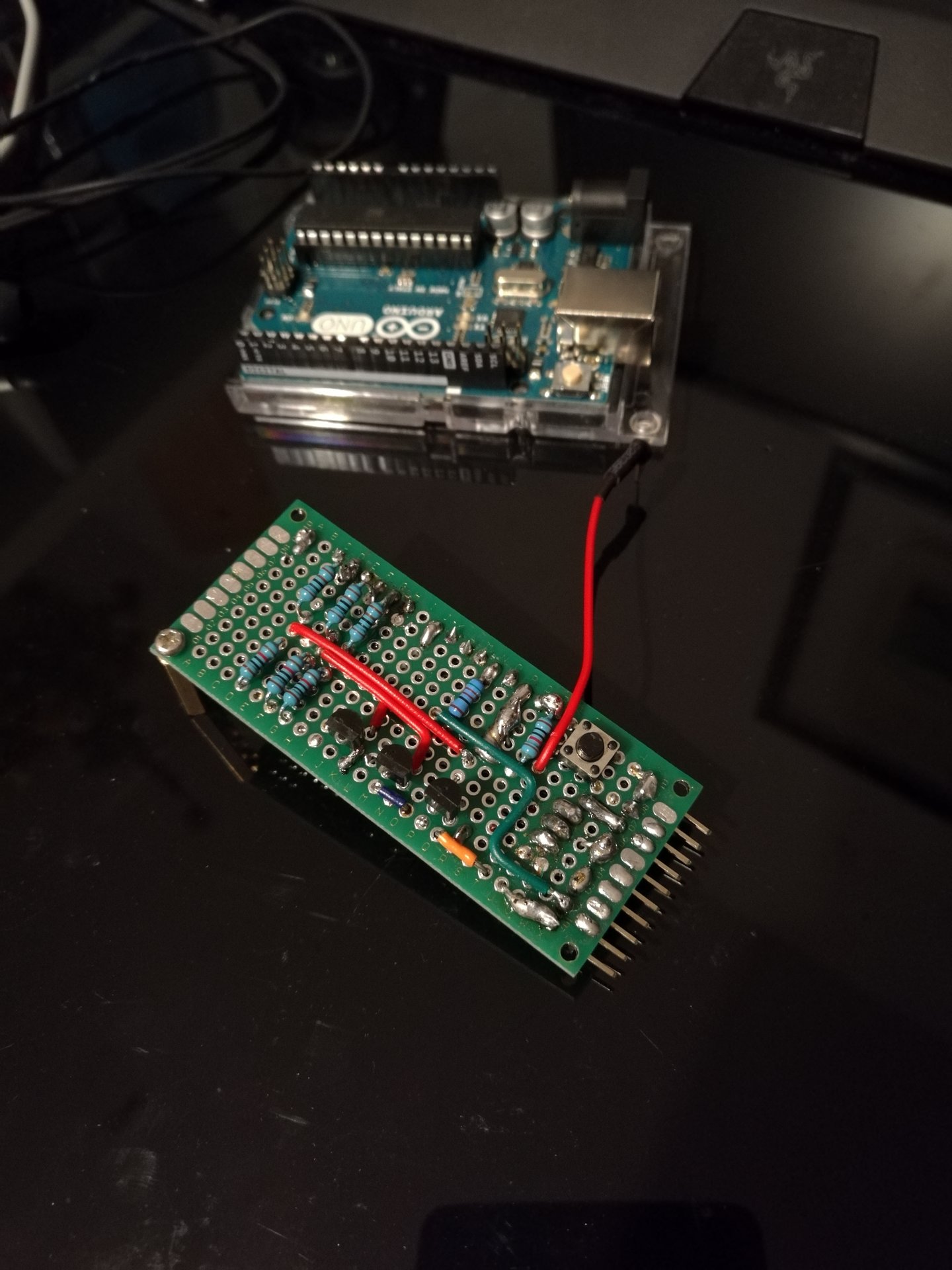


I had to bend the pins, because I discovered that the Arduino connector doesn’t follow the standard…